Note: Descriptions are shown in the official language in which they were submitted.
CA 02509935 2005-06-13
WO 2004/055333 PCT/CA2003/001770
- 1 -
GRON~ETED BYPASS DUCT PENETRATION
TECHNICAL FIELD
[0001] The invention relates to a thin-walled duct
penetration sealing grommet, particularly useful for
sealing between an opening in a gas turbine engine bypass
duct wall and the external surface of a projection
extending through the opening to simplify manufacture by
eliminating complex joint configurations, while
accommodating pressure differential, and relative thermal
expansion and contraction.
BACKGROUND OF THE ART
[0002] The bypass duct of a turbofan gas turbine
engine contains a pressurized flow of air between the
outer duct wall and the engine core. At several
locations along the length and about the circumference of
the annular bypass duct, penetrations are necessary for
conveying fuel, oil, control cables or compressed air
bleed from the compressor to an aircraft cabin, as well
as many control and monitoring penetrations for
instrumentation, inspection and maintenance.
[0003] In the prior art, penetrations through the
bypass duct are generally accomplished by shrouding the
conduits or cables in a transverse sheet metal projection
that may be contoured for improved aerodynamic
properties. The intersection between the transverse
sheet metal projection and the.sheet metal walls of the
bypass duct are generally manufactured with a flange that
is riveted or faulted to the relatively thin sheet metal
bypass duct walls. Such connections however must also
CA 02509935 2005-06-13
WO 2004/055333 PCT/CA2003/001770
- 2 -
accommodate the difference in pressure between the
pressurized flow of air through the bypass duct and the
ambient air surrounding the exterior of the engine.
Further, the engine core and the associated inner bypass
duct wall are exposed to significant heat and thermal
expansion and contraction relative to the less exposed
outer bypass wall. As a result, relative thermal
expansion and contraction is also accommodated by the
connection between the projection and the outer bypass
wall or the inner bypass wall depending on the particular
arrangement.
[00,04] As a result of the pressure differential and
need to accommodate relative thermal expansion and
contraction, the sealing and mechanical connection
between projections through the bypass wall,and the
relatively thin bypass duct walls is a relatively complex
arrangement requiring clearance for expansion and
contraction,'resilient seals and quite often involves
riveting a structural support or containment flange to
the relatively thin bypass duct walls surrounding the
opening for the penetration.
[0005] It is an object of the invention to provide a
means to seal between the opening and the gas turbine
engine bypass duct wall and the external surface of a
projection extending through the opening which
accommodates relative thermal expansion and contraction
and pressure differential in a simple low cost manner.
[0006] Further objects of the invention will be
apparent from review of the disclosure, drawings and
description of the invention below.
CA 02509935 2005-06-13
WO 2004/055333 PCT/CA2003/001770
- 3 -
DISCLOSURE OF THE INVENTION
[0007] The invention provides a bypass duct sealing
grommet, for sealing between an opening in a gas turbine
engine bypass duct wall and the external surface of a
projection extending through the opening.
Conventionally, the intersection between the projection
and the sheet metal bypass duct requires accurate fitting
and welding, but cannot then accommodate thermal
expansion and contraction. The grommet enables an
oversized opening for accommodating relative thermal
motion and simplifies manufacture. The grommet has an
annular body with a central aperture adapted to seal
against.the external surface of the projection and two
flanges defining an external slot about an exterior
periphery of the body to contain and seal the bypass duct
wall between the flanges.
DESCRIPTION OF THE DRAWINGS
[0008] In order that the invention may be readily
understood, one embodiment of the invention is
illustrated by way of example in the accompanying
drawings.
[0009] Figure 1 is an axial cross-sectional view
through a typical turbofan gas turbine engine showing the
general arrangement of internal components and in
particular the numerous penetrations through the outer
annular bypass duct.
(00010] Figure 2 is a radial cross-sectional view
through the bypass duct on line 2-2 of Figure 1.
CA 02509935 2005-06-13
WO 2004/055333 PCT/CA2003/001770
- 4 -
[00011] Figure 3 is a detailed axial cross-sectional
view through a prior art penetration through the bypass
duct shown along the line 3-3 of Figure 2.
(00012] Figure 4 is an axial cross-sectional view along
the line 4-4 of Figure 2 showing another example of the
prior art penetration through the bypass duct wall.
[00013] Figure 5 is a partially cut away perspective
view of a penetration through the bypass duct wall with a
connecting grommet in accordance with the invention.
[00014] Figure 6 is a detailed cross-sectional view
through a sealing grommet and adjoining sheet metal walls
of the bypass duct and projecting penetration showing the
symmetrical trapezoidal cross-sectional profile of the
grommet when the bypass wall and a wall of the projection
are in a perpendicular orientation.
[000151 Figure 7 shows the deformations of the grommet
to accommodate an acute angular orientation.
[00016] Figure 8 shows the deformation of the grommet
when relative radial motion is encountered between the
bypass wall and a wall of the projection as a result of
internal pressure or thermal expansion for example.
[00017] Further details of the invention and its
advantages will be apparent from the detailed description
included below.
25~ DETAILED DESCRIPTION OF PREFERRED EMBODIMENTS
[00018] Figure 1 shows an axial cross-section through a
turbofan gas turbine engine. It will be understood
however that the invention is also applicable to any type
CA 02509935 2005-06-13
WO 2004/055333 PCT/CA2003/001770
- 5 -
of engine with a thin-walled air duct with a
penetrations) requiring sealing. Air intake into the
engine passes over fan blades 1 in a fan case 2 and is
then split into an outer annular flow through the bypass
duct 3 and an inner flow through the low-pressure axial
compressor 4 and high-pressure centrifugal compressor 5.
Compressed air exits the compressor 5 through a diffuser
6 and is contained within a plenum 7 that surrounds the
combustor 8. Fuel is supplied to the combustor 8 through
fuel tubes 9 whichlis mixed with air from the plenum 7
when sprayed through nozzles into the combustor 8 as a
fuel air mixture that is ignited. A portion of the '
compressed air within the plenum 7 is admitted into the
combustor 8 through orifices in the side walls to create
a cooling air curtain along the combustor walls or'is
used for cooling to eventually mix with the hot gases
from~the combustor and pass over the nozzle guide vane 10
and turbines 11 before exiting the tail of the engine as
exhaust.
[00019] Figure 1 illustrates numerous projections and
penetrations through the bypass duct 3. Penetrations
project through relatively thin sheet metal inner bypass
wall 12 and sheet metal or fiber composite outer bypass
wall 13. While the accessory gear box 14 has a
relatively rigid metal casing that extends through the
bypass duct 3, smaller penetrations or projections are
also required such as the compressed air bleed valve 15,
penetrations for fuel supply lines 16, lubricating oil
supply line 17 and igniter 18.
[00020] Figure 2 is a radial cross-sectional view on
line 2-2 of Figure 1 showing five penetrating projections
19 extending between the inner bypass wall 12 and outer
CA 02509935 2005-06-13
WO 2004/055333 PCT/CA2003/001770
- 6 -
bypass wall 13 for internally housing various conduits
and other services extending between the exterior surface
of the engine and the central engine core.
[00021] Figure 3 shows an example axial cross-sectional
detail view through a conventional prior art projection
19 having an outer flange 20 mounted to the outer bypass
wall 13 with a resilient gasket 21. The projection 19
includes an internal end wall 22 fixed with bolts 23 to
the inner bypass wall 12. It will be appreciated that
the bypass duct 3 contains an annular flow of fast moving
pressurized air which is sealed from the ambient external
air with the gasket 21. Further the relative positions
of the inner bypass wall 12 and outer bypass wall 13 vary
due to relative thermal expansion and contraction, as
well as flexural deflection due to air pressure
differential between the bypass duct 3 and ambient
external air. In the prior art therefore, the gasket 21
accommodates radial movements and seals the duct 3. The
outer bypass wall 13 includes an oversized opening 24 in
the thin wall 13 which is reinforced and surrounded by an
angle flange 25 riveted to the outer bypass duct wall 13.
The angle flange 25 retains the gasket 21 and
structurally reinforces the bypass duct wall 13 which is
weakened as a result of the opening 24. The opening 24
is oversized in order to accommodate an assembly
tolerance in manufacturing and also to accommodate
relative movement due to pressure differential, and
thermal expansion and contraction between the projection
19 and the outer bypass duct wall 13.
[00022] Another example of prior art projection 19 is
shown in Figure 4 which has an end wall 22 secured with
bolts 23 to a receiving flange in the inner bypass duct
CA 02509935 2005-06-13
WO 2004/055333 PCT/CA2003/001770
12. To accommodate relative expansion and contraction
between the inner bypass wall 12 and outer bypass wall
13, bellows 26 extend between a flange 20 of the
projection 19 and a mounting plate 27 that is bolted to a
supporting plates and riveted to the relatively thin
outer bypass duct wall 13.
[00023] As is apparent from the details of Figure 3 and
4 and explanation above; the need to accommodate relative
thermal expansion and contraction between the inner
bypass duct wall 12 and outer bypass duct wall 13, and to
accommodate the pressure differential between the bypass
duct 3 and outer ambient air, has resulted in relatively
complex structures in the prior art that require accurate
fitting, gaskets, bellows and numerous fasteners, rivets
and reinforcing flanges.
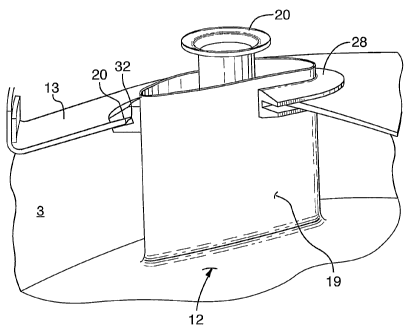
[00024] Figure 5 is a partially cut away perspective
view of a bypass duct sealing grommet 28 that provides a
simple low cost means to seal between an opening 24 in
the gas turbine engine outer bypass duct wall 13 and the
external surface of the projection 19 which extends
through the opening 24. Figure 6 shows a detailed
sectional view through the sealing grommet 28 which
comprises an annular body with a central aperture having
an interior peripheral surface 29 that is adapted to seal
against the external surface of the projection 19.
[00025] As shown in Figure 6, a first flange 30 and a
second flange 31 define an external slot 32 which extends
completely about the exterior periphery of the grommet
annular body and is adapted to receive and seal the
relatively thin bypass duct wall 13 between the flanges
30 and 31. For simplicity in Figures 6, 7 and 8 the
CA 02509935 2005-06-13
WO 2004/055333 PCT/CA2003/001770
_ g _
bypass duct wall 13 is shown as a planar member however
it will be appreciated from viewing Figures 1 and 2 that
the bypass duct wall 13 actually has a radial curvature
and an axial curvature which requires that the grommet 28
has the capacity to deform while maintaining the ability
to seal and resist the forces caused by pressure
differential on opposing sides of the bypass duct wall
13. The grommet 28 must adapt to changes in the
orientation of the wall 13 relative to the projection 19
due to the complex curvature of the wall 13 while
permitting a degree of relative thermal expansion and
contraction and further permitting a degree of
manufacturing tolerance in fitting and sealing between
the wall 13 and projection 19.
[00026] Figure 7 shows the manner in which the grommet
28 can be deformed to accommodate an angular orientation
indicated by angle "cc" whereas Figure 8 illustrates
distortion of the grommet 28 to accommodate radial motion
of the bypass duct wall 13 relative to the projection 19
which may be caused by pressure differential or expansion
and contraction for example.
[00027] In order to ensure that installation of the
grommet 28 is not inadvertently reversed, preferably the
annular body of the grommet 28 has a uniform cross-
sectional profile symmetric about the slot 32. As a
result, during installation the grommet 28 cannot be
installed upside down. As will be appreciated by those
skilled in the art, the grommet 28 may be molded of
silicon in an injection molding process or may be
extruded as a silicon strip of uniform cross-section
through an extrusion process to create an elongate
sealing strip of uniform cross-sectional profile. During
CA 02509935 2005-06-13
WO 2004/055333 PCT/CA2003/001770
- 9 -
installation, a first end of the elongate sealing strip
and a mating second end of the strip abut at a joint
which may be secured with adhesives or heat resistant
silicon caulking if necessary.
[00028] As shown in Figures 6, 7 and. 8, preferably, the
uniform cross-sectional profile of the grommet annular
body 28 is trapezoidal with a relatively thick collar 33
about the periphery of the projection 19 connecting the
first and second flanges 30 and 31. The flanges 30 and
31 have a tapered profile which together with the collar
33 provides a variation in resistance to distortion or
bending between the relatively flexible outer tip of the
flanges 30 and 31 and the stiffer abutting interior
peripheral surface 29 which. seals against the projection
19. As seen in Figures 7 and 8, the trapezoidal profile
and use'of the collar 33 increases the tendency of the
grommet 28 to jam and interfere with relative movement
between the outer bypass duct wall 13 and the projection
19. Jamming or distortion creates a resilient or biasing
force between the interior peripheral surface 29 and the
surface of the projection 19 without the need for
embedded springs in the grommet 28. As a result, the
seal created by the distorted grommet 28 maintains the
pressure differential between opposite surfaces of the
outer bypass duct wall 13 while distortion of the grommet
28 permits a degree of relative movement to accommodate
thermal expansion and contraction as well as to
accommodate variation in the curvature of the outer
bypass duct wall 13 and its angular orientation relative
to the projection 19.
[00029] As in the prior art, the opening 24 which
permits the passage of the projection 19 through the
CA 02509935 2005-06-13
WO 2004/055333 PCT/CA2003/001770
- 10 -
outer bypass wall 13 is oversized in order to permit
manufacturing and assembly tolerance and to accommodate
relative thermal expansion or contraction or distortion
as a result of pressure differential.
[00030] With reference to Figures 5, 6, 7 and 8, the
collar 33, flanges 30 and 31 and opening 24 in the bypass
duct wall 13 define an annular clearance gap 34
therebetween. The clearance gap 34, as seen in Figure 6,
permits use of an oversized hole 24 with an acceptable
assembly and manufacturing tolerance and ability to
accommodate relative movement between the bypass duct
wall 13 and the projection 19.
[00031] As seen in Figures 7 and 8 however the
clearance gap 34 also permits resilient distortion of the
slot 32 and adjacent flanges 30 and 31 to improve the
capacity of the grommet 28 to accommodate movement and
orientation of the outer bypass duct 13 relative to the
projection 19. Therefore, comparing the relatively
complex arrangements required by the prior art as
illustrated in Figure 3, in particular compared to the
use of the bypass duct sealing grommet 28 as illustrated
in Figure 5, significant savings in assembly cost and
simplicity of manufacture are achieved.
[00032] Although the above description relates to a
specific preferred embodiment as presently contemplated
by the inventors, it will be understood that the
invention in its broad aspect includes mechanical and
functional equivalents of the elements described herein.