Note: Descriptions are shown in the official language in which they were submitted.
CA 02509961 2005-06-13
WO 2004/062005
PCT/US2003/035722
Description
COMPOSITE MATERIAL AND CURRENT COLLECTOR FOR BATTERY
Technical Field
This invention relates generally to a composite material and, more
particularly, to a composite material current collector for an energy storage
device.
Background
Lead acid batteries are known to include at least one positive
current collector, at least one negative current collector, and an
electrolytic
solution including, for example, sulfuric acid (H2504) and distilled water.
Ordinarily, both the positive and negative current collectors in a lead acid
battery
are constructed from lead. The role of these lead current collectors is to
transfer
electric current to and from the battery terminals during the discharge and
charging processes. Storage and release of electrical energy in lead acid
batteries
is enabled by chemical reactions that occur in a paste disposed on the current
collectors. The positive and negative current collectors, once coated with
this
paste, are referred to as positive and negative plates, respectively. A
notable
limitation on the durability of lead acid batteries is corrosion of the lead
current
collector of the positive plate.
The rate of corrosion of the lead current collector is a major factor
in determining the life of the lead acid battery. Once the sulfuric acid
electrolyte
is added to the battery and the battery is charged, the current collector of
each
positive plate is continually subjected to corrosion due to its exposure to
sulfuric
acid and to the anodic potentials of the positive plate. One of the most
damaging
effects of this corrosion of the positive plate current collector is volume
expansion. Particularly, as the lead current collector corrodes, lead dioxide
is
formed from the lead source metal of the current collector. This lead dioxide
CA 02509961 2005-06-13
WO 2004/062005
PCT/US2003/035722
-2-
corrosion product has a greater volume than the lead source material consumed
to
create the lead dioxide. Corrosion of the lead source material and the ensuing
increase in volume of the lead dioxide corrosion product is known as volume
expansion.
Volume expansion induces mechanical stresses on the current
collector that deform and stretch the current collector. At a total volume
increase
of the current collector of approximately four percent (4%) to seven percent
(7%), the current collector may fracture. As a result, battery capacity drops,
and
eventually, the battery will reach the end of its service life. Additionally,
at
advanced stages of corrosion, internal shorting within the current collector
and
rupture of the cell case can occur. Both of these corrosion effects may lead
to
failure of one or more of the cells within the battery.
One method of extending the service life of a lead acid battery is
to increase the corrosion resistance of the current collector of the positive
plate.
Several methods have been proposed for inhibiting the corrosion process in
lead
acid batteries. Because carbon does not oxidize at the temperatures at which
lead
acid batteries generally operate, some of these methods have involved using
carbon in various forms to slow or prevent the detrimental corrosion process
in
lead acid batteries. For example, U.S. Patent No. 5,512,390 (hereinafter the
'390
patent) discloses a lead acid battery that includes current collectors made
from
graphite plates instead of lead. The graphite plates have sufficient
conductivity to
function as current collectors, and they are more corrosion resistant than
lead.
Substituting graphite plates for the lead current collectors may, therefore,
lengthen the life of a lead acid battery.
While the battery of the '390 patent may potentially offer a
lengthened service life as a result of reduced corrosion at the positive
plate, the
graphite plates of the '390 patent are problematic. For example, the graphite
plates of the '390 patent are dense, flat sheets of material each having a
relatively
small amount of surface area. Unlike lead electrode plates of a conventional
lead
CA 02509961 2013-02-26
- 3 -
acid battery, which are generally patterned into a grid-like structure to
increase the
available surface area of the plates, the graphite plates of the '390 patent
are smooth
sheets with no patterning. In lead acid batteries, an increase in surface area
of the current
collector may increase the specific energy of the battery and, therefore, may
translate into
improved battery performance. More surface area on the current collectors may
also lead
to a reduction in the time required for charging and discharging of the
battery. The
relatively small surface area of the graphite plates of the '390 patent
results in poorly
performing batteries that have slow charging speeds.
Additionally, the graphite plates of the '390 patent lack the toughness of
lead
current collectors. The dense graphite plates of the '390 patent are brittle
and may
fracture when subjected to physical shock or vibration. Such physical shock
and
vibration commonly occur in vehicular applications, for example. Any
fracturing of the
graphite plates would lead to the same problems caused by volume expansion of
ordinary
lead current collectors. Therefore, despite offering an increased resistance
to corrosion
compared to conventional lead current collectors, the brittle nature of the
graphite plates
of the '390 patent could actually result in battery service lives shorter than
those possible
through use of ordinary lead current collectors.
The present invention is directed to overcoming one or more of the problems or
disadvantages existing in the prior art.
Summary of the Invention
One aspect of the present invention includes a composite material. The
composite
material includes a first carbon foam layer including a network of pores and a
second
carbon foam layer including a network of pores. An intermediate bonding layer
is
disposed between the first and second carbon foam layers, and permeates at
least some of
the pores of the first carbon foam layer and at least some of the pores of the
second
carbon foam layer.
A second aspect of the present invention includes a method of making a
composite material. This method includes providing a first sheet of carbon
foam
including a network of pores and applying a layer of bonding material to the
first sheet of
carbon foam. A second sheet of carbon foam, which includes a network of pores,
is then
CA 02509961 2013-02-26
- 4 -
placed on the layer of bonding material to form a stacked structure. Heat is
applied to the
stacked structure to soften the layer of bonding material, in order to
facilitate the
permeation of the bonding material into the pores of the first and second
sheets of carbon
foam. Pressure is then applied to the stacked structure. The layer of bonding
material
permeates at least some of the pores of the first carbon foam layer and at
least some of
the pores of the second carbon foam layer.
Another aspect of the present invention includes a current collector for a
battery.
The current collector includes a first carbon foam layer having a network of
pores, and a
first electrical connection element provided on the first carbon foam layer.
An
intermediate bonding layer is provided on the first electrical connection
element and the
first carbon foam layer, and a second carbon foam layer, including a network
of pores, is
provided on the intermediate bonding layer. The intermediate bonding layer
permeates at
least some of the pores of the first carbon foam layer and at least some of
the pores of the
second carbon foam layer.
Another aspect of the invention provides A current collector for a battery,
comprising: the composite material as described herein, and at least one
electrical
connection element disposed between the first carbon foam layer and the second
carbon
foam layer.
Another aspect of the present invention comprises a battery comprising: a
housing; a positive terminal and a negative terminal external to the housing;
at least one
cell disposed within the housing and including at least one positive plate and
at least one
negative plate connected to the positive terminal, respectively, the at least
one positive
plate including the aforesaid current collector having a chemically active
paste disposed
on the first and second carbon foam layers such that the chemically active
paste
penetrates at least some of the pores of both the first and second carbon foam
layers; and
an electrolytic solution filling a volume between the positive and negative
plates.
CA 02509961 2013-02-26
- 4a -
Brief Description of the Drawings
The accompanying drawings, which are incorporated in and constitute a part of
this specification, illustrate exemplary embodiments of the invention and,
together with
the written description, serve to explain the principles of the invention. In
the drawings:
Fig. 1 is a cross-sectional view of a composite material in accordance with an
exemplary embodiment of the present invention;
Fig. 2A is a plan view of a current collector in accordance with an exemplary
embodiment of the present invention;
Fig. 2B is a cross-sectional view of the current collector of Fig. 2A taken
along
the line 2A;
Fig. 3 illustrates an electrical connection element according to an exemplary
embodiment of the present invention;
Fig. 4A is a plan view of another current collector in accordance with an
exemplary embodiment of the present invention;
Fig. 4B is a cross-sectional view of the current collector of Fig. 4A taken
along
the line 4A;
CA 02509961 2005-06-13
WO 2004/062005
PCT/US2003/035722
-5-
Fig. 5 is a diagrammatic cut-away representation of a battery in
accordance with an exemplary embodiment of the present invention.
Detailed Description
In the following description, reference is made to the
accompanying drawings that form a part thereof, and in which is shown by way
of illustration specific exemplary embodiments in which the invention may be
practiced. These embodiments are described in sufficient detail to enable
those
skilled in the art to practice the invention, and it is to be understood that
other
embodiments may be utilized and that changes may be made without departing
from the scope of the present invention. The following description is,
therefore,
not to be taken in a limited sense. Wherever possible, the same reference
numbers are used throughout the drawings to refer to the same or like parts.
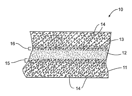
As shown in Fig. 1, composite material 10 includes two layers of
porous carbon foam 11, 13. A intermediate layer of bonding material 12 is
disposed between carbon foam layers 11 and 13. Bonding material 12 attaches
carbon foam layers 11 and 13 together and provides structural support for
composite material 10.
The carbon foam used to form carbon foam layers 11 and 13 of
composite material 10 is electrically conductive. In certain forms, the carbon
foam may offer sheet resistivity values of less than about 1 ohm/cm. In still
other
forms, the carbon foam may have sheet resistivity values of less than about
0.75
ohm/cm. The electrical conductivity of carbon foam layers 11 and 13 allows
composite material 10 to be used in a variety of applications such as, for
example, current collectors in batteries.
The carbon foam used to form carbon foam layers 11 and 13 of
composite material 10 is also resistant to corrosion. In general, carbon
oxidizes
only at very high temperatures and will resist corrosion even in corrosive
environments. The carbon foam used in composite material 10 retains this
CA 02509961 2005-11-10
=
-6-
corrosion resistance, and therefore, composite material 10 may be used, for
example, in the corrosive environment of a lead acid battery.
Additionally, carbon foam layers 11 and 13 are lightweight due to
the presence of a network of pores 14. The carbon foam of the present
invention
may include a total porosity value of at least 60%. In other words, at least
60%
of the volume of carbon foam layers 11 and 13 is included within pores 14.
Moreover, the carbon foam may have an open porosity value of at least 90%. In
,
other words, at least 90% of pores 14 are open to adjacent pores such that the
network of pores 14 forms a substantially open network. This open network of
pores 14 may result in a density of less than about 0.6 gm/cm3 for each of
carbon
foam layers 11 and 13. Further, the average pore size of the carbon foam may
be
between about 0.25 mm and about 2.0 mm.
In addition to carbon foam, graphite foam may also be used to
form composite material 10. One such graphite foam, under the trade name
PocoFoamTm, is available from Poco Graphite, Inc. The density and pore
structure of graphite foam may be similar to carbon foam. A primary difference
between graphite foam and carbon foam is the orientation of the carbon atoms
that make up the structural elements of the foam. For example, in carbon foam,
the carbon may be primarily amolphous. In graphite foam, however, much of the
carbon is ordered into a graphite, layered structure. Because of the ordered
nature of the graphite structure, graphite foam offers higher conductivity
than
carbon foam. PocoFoamTm graphite foam exhibits electrical resistivity values
of
between about 100 microohm-cm and about 400 microohm-cm.
In composite material 10, bonding material 12 is disposed between
carbon foam layers 11 and 13. Bonding material 12 attaches carbon foam layers
11 and 13 together by permeating at least some of pores 14 of carbon foam
layer
11 and at least some of pores 14 of carbon foam layer 13. In an exemplary
embodiment, bonding material 12 permeates the pores of carbon foam layer 11
by a depth equal to or greater than an average pore size of layer 11.
Similarly, in
CA 02509961 2005-06-13
WO 2004/062005
PCT/US2003/035722
-7-
the exemplary embodiment, bonding material 12 may permeate the pores of
carbon foam layer 13 by a depth equal to or greater than an average pore size
of
layer 13. The depth of permeation of bonding material 12 into carbon foam
layers 11 and 13 is not limited to depths of at least the average pore size of
layers
11 and 13. Rather, a suitable bond may be created with a penetration depth
sufficient to include at least one carbon structure (e.g., elements bordering
a pore)
within foam layers 11 and 13. The permeation of bonding material 12 into
carbon
foam layers 11 and 13 is represented in Fig. 1 by permeation zones 15 and 16,
respectively.
A variety of materials may be used as bonding material 12.
Bonding material 12 may include an electrically insulating material including
a
polymer. For example, in one embodiment, bonding material 12 may include
polypropylene. In yet another embodiment, bonding material 12 may include any
of a wide range of epoxies. In still another embodiment, an electrically
conductive material may be used as bonding material 12. Such electrically
conductive materials may include, for example, various metals and electrically
conductive polymers.
To make the composite material of the present invention, a layer
of bonding material is applied to a sheet of carbon foam material. Next, a
second
sheet of carbon foam material is placed on the layer of bonding material to
form a
stacked structure. If the bonding material is applied as a solid, such as in
the case
of most polymers and metals, then heat may be applied to the stacked structure
to
soften and/or melt the bonding material. Softening and/or melting of the
bonding
material encourages permeation of the bonding material into the pores of the
carbon foam. In addition to heat, pressure can also be applied to the stacked
structure. The application of external pressure may aid in forcing the bonding
material to permeate the pores of the carbon foam. In an exemplary embodiment
of the present invention, heat and pressure are applied simultaneously. In
certain
situations, however, heat may be applied exclusive of pressure. In still other
CA 02509961 2005-06-13
WO 2004/062005
PCT/US2003/035722
-8-
situations, the application of heat may occur separate from the application of
pressure.
In instances where the bonding material is applied as a liquid, such
as an epoxy, for example, the bonding material may permeate the pores of each
of
the two sheets of carbon foam without the need for applying heat or pressure.
Nevertheless, even in the case of bonding materials applied as a liquid, the
application of heat and pressure may facilitate peimeation of the bonding
material
into the pores of the carbon foam by reducing the viscosity of the bonding
material.
Figs. 2A and 2B illustrate a current collector 20 that includes the
composite material of the present invention. As shown in Figs. 2A and 2B,
current collector 20 includes carbon foam layers 11 and 13 bonded together by
a
conductive bonding material 22. Bonding material 22 permeates at least some of
the pores of the carbon foam layers 11 and 13. Further, bonding material 22
may
permeate the pores of carbon foam layers 11 and 13 by a depth equal to or
greater
than an average pore size of layers 11 and 13, respectively.
An electrical connection element 21 is disposed within bonding
material 22 and provides an external, electrical connection for current
collector
20. Electrical connection element 21 includes a tab 31 that extends beyond an
edge of either or both of carbon foam layers 11 and 13. Electrical connection
element 21 also includes at least one electrically conductive portion 33 (Fig.
3)
that extends within current collector 20.
In the exemplary embodiment shown in Figs. 2A and 2B, bonding
material 22 of current collector 20 is an electrically conductive material.
For
example, bonding material 22 may include a metal or an electrically conductive
polymer. Because bonding material 22 is electrically conductive, an external
electrical connection to current collector 20 may be made using only one
electrical connection element 21. Particularly, tab 31 can make electrical
contact
to both carbon foam layers 11 and 13 through bonding material 22.
CA 02509961 2005-06-13
WO 2004/062005
PCT/US2003/035722
-9-
Fig. 3 illustrates an electrical connection element 21 according to
an exemplary embodiment of the present invention. Electrical connection
element 21 includes tab 31 and at least one electrically conductive portion 33
that
extends away from tab 31. While tab 31 and the at least one electrically
conductive portion 33 may be made from metal, in the exemplary embodiment
shown in Fig. 3, both tab 31 and the electrically conductive portion 33 are
formed
from a plurality of carbon fibers. Specifically, tab 31 may be formed by a
plurality of carbon fibers arranged adjacent to one another and bonded
together.
Extending from tab 31, the plurality of carbon fibers may be spread apart to
form
electrically conductive portion 33. Spreading the fibers, as shown in Fig. 3,
provides a relatively even distribution of carbon fibers throughout current
collector 20, for example. Such a distribution helps to maintain good
electrical
contact between tab 31 and carbon foam layers 11 and/or 13.
Tab 31 may also include a coating 32 that can be used to form
certain types of electrical connections to tab 31. For example, where carbon
fibers are used to make tab 31, coating 32 may include a metal. Such a metal
coating may improve the durability of tab 31 and promote good electrical
contact
between tab 31 and external circuitry.
Figs. 4A and 4B illustrate another current collector 40 including
the composite material of the present invention. As shown in Figs. 4A and 4B,
current collector 40 includes carbon foam layers 11 and 13 bonded together by
a
bonding material 42. Similar to the bonding material of composite material 10,
bonding material 42 permeates at least some of the pores of the carbon foam
layers 11 and 13. Further, bonding material 42 may permeate the pores of
carbon
foam layers 11 and 13 by a depth equal to or greater than an average pore size
of
layers 11 and 13, respectively.
In the exemplary embodiment shown in Figs. 4A and 4B, bonding
material 42 is an electrically insulating material. Because bonding material
42 is
electrically insulating, an external electrical connection to current
collector 40
CA 02509961 2005-06-13
WO 2004/062005
PCT/US2003/035722
-10-
may be made using two electrical connection elements 21. Particularly, when
making current collector 40, a first electrical connection element 21 may be
disposed on, for example, carbon foam layer 11. Then, bonding material 42 is
applied to both the first electrical connection element and to carbon foam
layer
11. Because electrically insulating bonding material 42 coats the first
electrical
connection element 21, an additional electrical connection element may be
required to make contact with carbon foam layer 13, which is applied to the
bonding material 42 to create a stacked structure. Therefore, prior to placing
carbon foam layer 13 on bonding material 42, a second electrical connection
element 21 may be placed on bonding material 42. The second electrical
connection element 21 provides an external electrical contact with carbon foam
layer 13.
Accordingly, two electrical connection elements 21 are shown in
Fig. 4B. Each resides at an original interface (i.e. prior to permeation of
bonding
material 42 into either of carbon foam layers 11 or 13) between bonding
material
42 and carbon foam layers 11 and 13, respectively. Electrical connection
elements 21, which may be configured as shown in Fig. 3, for example, do not
interfere with permeation of bonding material 42 into the pores of the
respective
carbon foam layers.
While the exemplary embodiment of the present invention
illustrated in Fig. 4B includes two electrical connection elements 21,
electrical
connections to the carbon foam layers 11 and 13 may be accomplished through
alternative configurations. For example, a single electrical connection
element 21
may be configured such that electrically conductive portions 33 make
electrical
contact to both carbon foam layers 11 and 13. For example, conductive portions
33 may be arranged such that some of the conductive portions contact foam
layer
11 and other conductive portions contact foam layer 13. Alternatively,
electrical
connection element 21 may be sized with a sufficient thickness relative to the
thickness of bonding material 42 such that a single connection element 21 may
CA 02509961 2005-06-13
WO 2004/062005
PCT/US2003/035722
-11-
contact both foam layers 11 and 13. In these exemplary instances, one
electrical
connection element 21 would be sufficient.
Fig. 5 illustrates a battery 100 in accordance with an exemplary
embodiment of the present invention. Battery 100 includes a housing 110 and
terminals 120, which are external to housing 110. At least one cell 130 is
disposed within housing 110. While only one cell 130 is necessary, multiple
cells
may be connected in series to provide a desired total potential of battery
100.
Each cell 130 may be composed of alternating positive and
negative plates immersed in an electrolytic solution including, for example,
sulfuric acid and distilled water. Both the positive and negative plates
include a
current collector packed with a paste material, including, for example, an
oxide of
lead. As noted above, Figs. 2A, 2B, 4A, and 4B illustrate current collectors
20
and 40 according to exemplary embodiments of the present invention that may be
used to faun the positive and/or negative plates of battery 100. Chemical
reactions in the paste disposed on the current collectors of the battery
enable
storage and release of energy. The composition of this paste, and not the
material
selected for the current collector, determines whether a given current
collector
functions as either a positive or a negative plate.
To create the positive and negative plates of battery 100, a
chemically active paste is applied to current collectors 20, 40 such that the
chemically active paste penetrates the network of pores in the carbon foam of
the
current collector. Initially, the chemically active paste that is applied to
the
current collectors 20, 40 of both the positive and negative plates may be
substantially the same in terms of chemical composition. For example, the
paste
may include lead oxide (Pb0). Other oxides of lead may also be suitable. The
paste may also include various additives including, for example, varying
percentages of free lead, structural fibers, conductive materials, carbon, and
extenders to accommodate volume changes over the life of the battery. In
practice, the constituents of the chemically active paste may be mixed with a
CA 02509961 2005-06-13
WO 2004/062005
PCT/US2003/035722
-12-
small amount of sulfuric acid and water to form a paste that may be disposed
within pores 14 of the current collectors 20, 40.
Once the paste has been deposited on current collectors 20, 40 the
positive and negative plates are formed. To create a positive plate, current
collectors 20, 40 including lead oxide paste, for example, are subjected to a
curing process. This curing process may include exposing the pasted current
collectors 20, 40 to elevated temperature and humidity to encourage growth of
lead sulfate crystals within the paste. To create the negative plate, current
collectors 20, 40 including the lead oxide paste may be left "as is", with the
exception of an optional step of drying.
When the positive and negative plates have been assembled
together to form the cells of a battery 100 (shown in Fig. 5), battery 100 is
subjected to a charging (i.e., formation) process. During this charging
process,
the cured paste of the positive plate is electrically driven to lead dioxide
(Pb02),
and the paste of the negative plate is converted to sponge lead. Conversely,
during subsequent discharge of the battery 100, the pastes of both positive
and
negative plates convert toward lead sulfate.
Industrial Applicability
The composite material of the present invention is useful in any of
a wide variety of applications where materials with corrosion resistance, high
surface area, electrical conductivity, or low weight would be desirable. In
one
possible application, the composite material of the present invention may
serve as
a current collector in a battery, such as a lead acid battery, for example.
Current
collectors may support the chemically active components of the battery and
promote the flow of current between terminals of the battery.
Because current collectors 20, 40 include carbon foam, these
current collectors resist corrosion even when exposed to sulfuric acid and to
the
anodic potentials of the positive plate in a lead acid battery. As a result,
the
CA 02509961 2005-06-13
WO 2004/062005
PCT/US2003/035722
-13-
battery may offer a significantly longer service life as compared to batteries
without carbon foam current collectors.
The carbon foam includes a network of pores, which provides a
large amount of surface area for each current collector 20, 40. Current
collectors
composed of carbon foam may exhibit more than 2000 times the amount of
surface area provided by conventional lead current collectors. The large
amount
of surface area associated with current collectors 20, 40 translates into
batteries
having large specific energy values. For example, because of the open cell,
porous network and relatively small pore size of the carbon foam materials,
the
chemically active paste of the positive and negative plates is intimately
integrated
with the conductive carbon material of current collectors 20, 40. Therefore,
electrons produced in the chemically active paste at a particular reaction
site must
travel only a short distance through the paste before encountering the
conductive
carbon foam of current collectors 20, 40. This current may then be carried by
the
electrically conductive portion 33 of the electrical connection element 21,
for
example.
As a result, batteries with carbon foam current collectors 20, 40
may offer improved specific energy and power values. In other words, these
batteries, when placed under a load, may sustain their voltage above a
predetermined threshold value for a longer time than batteries including
either
lead current collectors or graphite plate current collectors. Also, these
batteries
may discharge more quickly than batteries including either lead current
collectors
or graphite plate current collectors.
The increased specific power values offered by batteries of the
present invention also translate into reduced charging times. Therefore, the
batteries may be suitable for applications in which charging energy is
available
for only a limited amount of time. For instance, in vehicles, a great deal of
energy is lost during ordinary braking. This braking energy may be recaptured
and used to charge a battery of, for example, a hybrid vehicle. The braking
CA 02509961 2005-06-13
WO 2004/062005
PCT/US2003/035722
-14-
energy, however, is available only for a short period of time (i.e., while
braking is
occurring). In view of their reduced charging times, the batteries of the
present
invention may provide an efficient means for storing such braking energy.
The porous nature of the carbon foam current collectors also
creates an improved substrate for retaining the chemically active paste of the
energy storage device. By impregnating the paste into pores of the carbon foam
current collectors, the paste is less likely to separate from the current
collectors.
This property is important in vehicle and other applications where vibration
is
common.
Further, by including carbon foam current collectors having a
density of less than about 0.6 g/cm3, a battery may weigh substantially less
that
batteries including either lead current collectors or graphite plate current
collectors. Other aspects and features of the present invention can be
obtained
from a study of the drawings, the disclosure, and the appended claims.