Note: Descriptions are shown in the official language in which they were submitted.
CA 02510497 2005-06-22
GAS SEPARATOR FLUID CROSSOVER FOR WELL PUMP
Field of the Invention
This invention relates in general to electrical submersible pumps and in
particular to a gas separator having a fluid crossover that rotates.
Background of the Invention
A common type of well pump for petroleum production has a submersible
centrifugal pump and an electrical motor. The pump has a plurality of stages,
each
stage having an impeller and a diffuser. The motor rotates a shaft extending
through
the pump, which causes the impellers to rotate to pump the well fluid up the
well.
Another type of well pump, called a progressive cavity pump, rotates a helical
rotor
within a stator having a double helical cavity. In both types of pumps, if the
well
fluid contains gas, the gas is detrimental to the pumping efficiency.
Downhole gas separators are commonly employed with down hole pumps to
remove as much gas as feasible from the well fluid flowing into the intake of
the
pump. In standard downhole gas separators for centrifugal pumps, fluids are
drawn
into the intake of the separator and spun by way of various components that
are
intended to propel and separate the lighter gaseous well fluid components from
the
heavier liquid components. The heavier component is spun to the outer surface
of the
chamber while the lighter component remains in the central part of the
chamber.
In prior art down hole separators, both fluids are propelled into a passive or
static crossover. The crossover has a liquid passage that directs liquids back
to the
center and toward the inlet of the pump. The lighter components are direct
back by
gas passages toward the exterior of the gas separator for discharge into the
casing
annulus. Friction losses hinder the movement of the fluids through these
passages and
reduces the efficiency of the separation.
Summary of the Invention
The gas separator of this invention has a crossover with a hub section that
engages the shaft for rotating the crossover therewith. The crossover has a
helical
liquid passage having an inlet in fluid communication with the separating
section of
the gas separator for receiving the heavier components. The liquid passage has
an
outlet in fluid communication with the liquid outlet of the housing. The
crossover has
a gas passage having an inlet in fluid communication with the separating
section for
CA 02510497 2005-06-22
receiving the lighter components and an outlet in fluid communication with the
gas
outlet of the housing. Rotation of the crossover propels the liquid toward the
pump,
Preferably and propels the gas into the casing annulus, the outlet of the gas
passage has an exit angle less than 90 degrees. Also, preferably, the liquid
passage
extends completely around the crossover at least one time. In the preferred
embodiment, a radial distance from the liquid passage to the shaft decreases
continuously from the inlet to the outlet of the liquid passage. The gas
passage has a
flow area that is greater at the inlet than the outlet of the gas passage in
the example
shown.
Accordingly, in one aspect of the present invention there is provided a
submersible pump gas separator for a well pump, the separator having a housing
with
an inlet for receiving well fluid, a liquid outlet for delivering heavier
components of
the well fluid to a first destination, a gas outlet for discharging lighter
components of
the well fluid to a second destination, a rotatable shaft extending through
the housing,
a separating section in the housing for separating the heavier components into
an area
radially outward from the lighter components relative to the shaft, and a
crossover for
delivering the heavier components to the liquid outlet and the lighter
components to
the gas outlet, the crossover comprising:
a hub section that engages the shaft for rotating the crossover therewith;
a helical liquid passage having an inlet in fluid communication with the
separating section for receiving the heavier components and an outlet in fluid
communication with the liquid outlet of the housing; and
a gas passage having an inlet in fluid communication with the separating
section for receiving the lighter components and an outlet in fluid
communication
with the gas outlet of the housing.
According to another aspect of the present invention there is provided a
submersible pump gas separator for a well pump, comprising:
a tubular housing with an inlet for receiving well fluid;
a rotatably driven shaft extending through the housing;
a separating section in the housing that rotates with the shaft for separating
heavier components of the well fluid into an area radially outward from
lighter
components of the well fluid;
an outlet port in the housing for discharging the lighter components from the
housing;
-2-
CA 02510497 2005-06-22
a crossover member mounted to the shaft for rotation therewith, the crossover
member comprising:
a core portion that has a generally conical exterior with a larger diameter at
an
upstream end and a smaller diameter at a downstream end;
a shroud surrounding the core portion and having a generally conical interior
spaced from the conical exterior of the core portion;
an auger flight having an inner edge joining the core portion and an outer
edge
joining the shroud, defining a liquid passage between the core and the shroud
for
receiving the heavier components from the separating section and delivering
the
heavier components to the interior of the housing;
a gas passage having an inlet portion in the core and an outlet portion within
the auger flight, the outlet portion extending from the inner edge to the
outer edge of
the auger flight; and
an outlet port in the shroud that registers with the outlet portion of the gas
1 S passage and
is in fluid communication with the outlet port in the housing for discharging
the
lighter components exterior of the housing.
According to yet another aspect of the present invention there is provided a
method of separating heavier components from lighter components of well fluid
with
a downhole well pump, comprising:
(a) providing a gas separator with a separating section and a crossover, the
crossover having a helical liquid passage and a gas passage;
(b) connecting the gas separator to the pump;
(c) rotating the pump and the crossover;
(d) flowing well fluid into the separating section and separating the well
fluid
in the separating section into heavier and lighter components; then
(e) flowing the heavier components through the liquid passage and to the
pump; and
(f) flowing the lighter components into the gas passage and out a gas outlet
port of the gas separator.
-3-
CA 02510497 2005-06-22
Brief Description of the Drawings
An embodiment of the present invention will now be described more fully
with reference to the accompanying drawings in which:
Figure 1 is a side elevational view of an electrical submersible pump assembly
S constructed in accordance with this invention.
Figures 2A and 2B comprise an enlarged vertical sectional view of a portion
of the gas separator of the pump assembly of Figure 1.
Figure 3 is an enlarged sectional view of the fluid crossover of the gas
separator of Figure 2A.
Figure 4 is a top view of the fluid crossover of Figure 3.
Description of the Preferred Embodiment
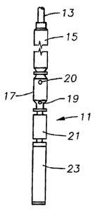
Referring to Figure 1, an electrical submersible pump assembly 11 is
suspended on a string of production tubing 13. Electrical submersible pump
assembly
11 comprises a conventional pump 15, which is typically a centrifugal pump
having a
large number of stages, each stage having an impeller and a diffuser. A gas
separator
17 connects to the intake end of pump 15 for separating gas from the well
fluid
entering pump 1 S. Gas separator 17 has an intake 19 for receiving well fluid
and a
plurality of discharge ports 20 for discharging gas to the annulus surrounding
assembly 11.
A seal section 21 connects to the intake end of gas separator 17. An
electrical
motor 23 connects to the opposite end of seal section 21. Seal section 21
equalizes
pressure of lubricant within motor 23 with that of the hydrostatic fluid
surrounding
motor 23.
Referring to Figure 2B, a drive shaft 25 extends through motor 23, seal
section
21, gas separator 17 and pump 15. Gas separator 17 may be of a variety of
types,
including a vortex type or one that has a rotating rotor, as shown in Figure
2B. In the
example shown, gas separator 17 includes an optional inducer 27 to increase
the
pressure of the fluid flowing into intake 19. Inducer 27 comprises a helical
flight that
rotates with shaft 25 within stationary housing 29 of gas separator 17. The
periphery
of the helical flight of inducer 27 is closely spaced to bore 31 of housing
29.
Gas separator 17 optionally may have a bearing 33 located at the upper end of
inducer 27. Bearing 33 is of a spider type, having a plurality of passages 35
extending
through it for the passage of the well fluid. Bearing 33 is stationary and
supports
-4-
CA 02510497 2005-06-22
shaft 25 in bore 31 of gas separator housing 29. The well fluid flows from
passages
35 to a set of rotating guide vanes 37 in this embodiment. Guide vanes 37
comprise a
plurality of curved plates that are inclined relative to the axis of shaft 25
to impart a
swirling motion to the well fluid. Guide vanes 37 rotate with shaft 25 and
deliver the
fluid to the separation section, which includes a separator rotor 39.
In this embodiment, rotor 39 has a rotating outer cylinder 41 that is closely
spaced to the sidewall of bore 31 of housing 29. Outer cylinder 41 is
supported by
and rotates with a hub 43 that is keyed to shaft 25 for rotation therewith.
Several rotor
vanes 45 extend between outer cylinder 41 and hub 43. Preferably, rotor vanes
45 are
located in radial planes that pass through the axis of shaft 25. Other types
of separator
rotors are also feasible. Rotor 39 causes centrifugal separation of the
heavier well
fluid components from the gas, resulting in the liquid components flowing up
the
inner diameter of cylinder 41. The gas components remain in the central area.
Refernng to Figure 2A, the separate liquid and gas streams flow to a fluid
1 S crossover 47, which rotates with shaft 25. Fluid crossover 47 directs the
liquid
components upward and radially inward and the gas components upward and
radially
outward. In this embodiment, the upper end of fluid crossover 47 extends to a
bearing
53 having a plurality of passages 51. The liquid components flow from passages
S 1
into bore 31 at the upper end of gas separator 17, as shown by the solid
arrows.
Crossover 47 has a central core 55, which preferably has a conical interior
and
exterior, each having a smaller diameter downstream end than its upper end.
Core SS
is supported inside a shroud 57 for rotation therewith. Shroud 57 also has a
conical
interior and exterior, each having a larger diameter at its upstream end and a
smaller
diameter at its downstream end. An auger flight 59 extends helically between
core 55
and shroud 57. Auger flight 59 extends completely around core SS at least one
turn,
and in the example, extends two to three turns. Auger flight 59 has an inner
edge that
joins core 55 and an outer edge that joins shroud 57, defining a helical
liquid passage
60 for the heavier liquid components, the flow of which is indicated by the
solid
arrows. The inlet to liquid passage 60 at the lower end of crossover 47 is
located
farther from shaft 25 than the outlet at the upper end of crossover 47.
Referring to Figure 3, crossover 47 has a hub 61 that is keyed to shaft 25
(Figure 2B) for rotation therewith. Hub 61 has a cylindrical exterior,
defining a
generally conical gas cavity 63 within core 55 between hub 61 and the conical
interior
surface of core 55. Core gas cavity 63 extends upward a selected distance
within core
-5-
CA 02510497 2005-06-22
55 and has a decreasing outer diameter. Gas cavity 63 is annular, and the flow
area of
gas cavity 63 decreases in a downstream direction.
Auger flight 59 is sufficiently thick in an axial direction to accommodate
several outlet passages 65, which are located between the upper and lower
sides of
auger flights 59. The axial thickness of auger flight 59 is thinner than the
distance
between turns of flight 59 in this embodiment. Passages 65 join gas cavity 63
and
lead to the outer edges of auger flights 59. Several outlet ports 67 are
formed in
shroud 57, each joining the outer end of one of the passages 65. As shown in
Figure
4, outlet ports 67 are circumferentially elongated, with centers about 120
degrees
apart from each other. Gas separator ports 20 are located within housing 29
radially
outward from shroud outlet ports 67 for receiving gas being discharged from
outlet
ports 67. Preferably, passages 65 are curved and incline away from the
direction of
rotation, as illustrated by the arrow in Figure 4. The inlet ends of passages
65 lead
the outlet ends of passages 65. This curvature creates an exit angle 66 that
is less than
90 degrees, which would be on a radial line. In the example shown, exit angle
66 is
about 70 degrees, but it could vary.
Referring to Figure 2A, rotor blades 45 may have notches 69 formed in their
upper edges between hub 43 and cylinder 41. An annular skirt (not shown) may
extend from crossover 47 downward into notches 69 to provide a physical
barrier
between the gas and liquid flowing from rotor 39 into crossover 47.
In operation, referring to Figure 1, electrical power supplied to motor 23
causes motor 23 to rotate shaft 25 (Figures 2A, 2B) to drive separator rotor
39 and
pump 15. Well fluid flows into gas separator intake 19. Refernng to Figure 2B,
inducer 27 increases the pressure of the well fluid and delivers it to guide
vane 37.
Rotating guide vane 37 imparts swirling motion to the well fluid and delivers
it to
rotating rotor 39 (Figure 2A). Rotor vanes 45 cause centrifugal separation of
the
liquid and gas components, with the liquid components flowing outward into
contact
with the outer cylinder 41 of rotor 39.
As shown in Figure 2A, the liquid components flow into the helical passage 60
located between auger flights 59. The solid arrows indicate the liquid
components
being delivered up through bearing passage 51 and from gas separator bore 31
into the
intake of pump 15 (Figure 1).
The gas components, being located near hub 43, pass into gas cavity 63 as
shown in Figure 3. The decreasing flow area of cavity 63 and the outward
inclined
-6-
CA 02510497 2005-06-22
passages 65 accelerate the gas through shroud outlet ports 67, as indicated by
the
dashed lines in Figure 2A. The gas flows out gas separator ports 20 into the
casing
annulus surrounding pump assembly 11.
The invention has significant advantages. The rotating crossover imparts
energy to the liquid and gas streams to improve the efficiency of the
separation. This
additional energy reduces friction losses of the flowing streams.
While the invention has been shown in only one of its forms, it should be
apparent to those skilled in the art that it is not so limited but is
susceptible to various
changes without departing from the scope of the invention.
_7_