Note: Descriptions are shown in the official language in which they were submitted.
CA 02510723 2005-06-27
SWITCH DEVICE
BACKGROUND OF THE INVENTION
1. Field of the Invention
The present invention relates to a switch device for use as,
for example, a door millur switch of a vehicle.
2. Description of the Related Art
An example of a conventional switch device of this type is
disclosed in Japanese Patent Laid-Open Publication No. 11-288644,
and is shown in FIGS. 10 and 11. FIG. 10 is a plan view of a
conventional switch device, and FIG. 11 is a sectional view
thereof.
A switch device 101 shown in FIGS. 10 and 11 is used for,
by way of example, changing and adjusting the direction of a
mirror surface of a left or right door mirror upward, downward,
rightward, or leftward. The switch device 101 includes a push
button 107 as a push operation body provided to an opening 105 of
a switch case 103.
The push button 107 is provided with four convex portions
109 as markers corresponding to up, down, right, and left
movements of the door mirror to indicate push operation portions.
The push button 107 is also provided with a flange 111 in the
=
CA 02510723 2005-06-27
opening 105.
The switch case 103 is provided with a wall 113 that
surrounds the perimeter of the flange 111. The wall 113 stops a
movement in a direction along the opening 105 of the flange 111
(such a movement is hereinafter simply referred to as a "lateral
movement" in the drawing) to regulate a still position of the
push button 107.
Between the push button 107 and the switch case 103, a
spring 115 is provided to force the push button 107 to a position
before pushing.
Correspondingly to each convex portion 109 indicating a
push position, an actuator 117 is supported by the switch case
103 so as to be able to move in an axial direction. Provided at
the bottom end of each actuator 117 is a rubber contact 119. The
rubber contact 119 is provided with a movable contact 121.
Opposite to the movable contact 121, a fixed contact 125 is
provided to an electrical circuit board 123.
Thus, upon pushing any one of the convex portions 109 on
the push button 107 for a tilting operation, the actuator 117
positioned at a side corresponding to this tilting is pressed to
the axial direction to be moved, thereby deforming the rubber
-2-
,
CA 02510723 2005-06-27
contact 119. With the deformation of the rubber contact 119, the
movable contact 121 comes into contact with the fixed contact 125.
With this contacting, a motor for operating the door mtiLLur is
driven via the circuit board 123, thereby allowing the direction
of the door mirror to be changed and adjusted upward, downward,
rightward, or leftward according to the pushing operation of the
push button 107.
When no tilting operation is performed on the push button
107, the push button 107 keeps the still position in the opening
105 by a force of the spring 115. At this time, the wall 113 is
adjacent to the outer perimeter of the flange 111, thereby
allowing the still position of the push button 107 to be
regulated by stopping the movement of the flange 111 by the wall
113.
However, the above-described structure poses problems such
that, at the time of a tilting operation of the push button 107,
a rubbing sound may occur and, due to a rubbing feeling, the
feeling of operation is not good.
FIG. 12 shows the structure of a push button similar to
that shown in FIGS. 10 and 11, and illustrates the state in which
the push button 107 is pushed for a tilting operation.
-3-
CA 02510723 2005-06-27
As shown in FIG. 12, when the push button 107 is pushed at
any of the convex portions 109, a force Fsine occurs in a lateral
direction with respect to a push operation force F. Therefore,
the push button 107 is laterally moved in the direction of the
force Fsin0 with respect to the opening 105. Therefore, during
the pushing operation, the flange 111 comes into contact with the
wall 113 to cause the rubbing sound and the rubbing feeling as
described Above.
SUMMARY OF THE INVENTION
Problems to be solved by the invention include an
occurrence of a rubbing sound and a reduction in the feeling of
operation due to a rubbing feeling.
One of the most main features of the present invention is
that, in order to allow suppression of a rubbing noise and
improvement in the feeling of operation, a supporting portion and
a supported portion that can be spaced apart from each other are
separately provided to the push operation body and the switch
case for rotational support and positional regulation of the push
operation body with respect to the switch case at the time of a
tilting operation by each pushing.
-4-
CA 02510723 2005-06-27
In the switch device according to the present invention,
the supporting portion and the supported portion that can be
spaced apart from each other are separately provided to the push
operation body and the switch case for rotational support and
positional regulation of the push operation by with respect to
the switch case at the time of a tilting operation by each
pushing. Therefore, at the time of the tilting operation on the
push operation body by the pushing, the supporting portion and
the supported portion can stop a force in a direction along an
opening of the switch case occurring at the time of the tilting
operation on the push operation body by a pushing. With this,
the movement of the push operation body with respect to the
opening can be regulated.
Thus, at the time of the tilting operation by pushing the
push operation hndy, a rubbing sound between the push operation
body and the switch case side can be suppressed.
Also, at the time of the tilting operation by pushing the
push operation body, a rubbing feeling can be suppressed, and the
feeling of operation of the push operation body can be improved.
In the case where the push operation body includes a flange
disposed in the switch case, and a push portion protruding
-5-
t
CA 02510723 2005-06-27
outward from the opening to the switch case and the supporting
portion and the supported portion are separately provided to the
flange and an inner surface of the switch case opposite to the
flange, rotational support and positional regulation of the
flange with respect to the switch case can be performed by the
supporting portion and the supported portion. With this, a
rubbing noise can be suppressed and the feeling of operation can
be improved.
In the case where the flange has a square shape in a plane
view and the supporting portion and the supported portion are
separately provided to a corner portion of the flange and a
portion of an inner surface of the switch case opposite to the
corner portion of the flange, the push operation body can have
four positions between the corner portions as push positions,
thereby improving a function of a switch device.
In the case where a swelled portion in a plane direction is
provided at the corner portion of the flange and the supporting
portion and the supported portion are separately provided to the
swelled portion and a portion of the inner surface of the switch
case opposite to the swelled portion, a distance between a point
for rotational support and positional regulation by the
-6-
CA 02510723 2005-06-27
supporting portion and the supported portion and the opening can
be increased, thereby reducing a tilting range of the push
operation body by a pushing. Therefore, the force occurring in
the direction along the opening at the time of the pushing can be
reduced. With this, suppression of a rubbing sound and an
improvement in the feeling of operation can be more reliably
achieved.
In the case where the supporting portion and the supported
portion are a convex portion and a concave portion each having a
spherical shape and engaging with each other, rotational support
and positional regulation of the push operation body with respect
to the switch case can be more reliably and smoothly performed.
With this, suppression of a rubbing sound and an improvement in
the feeling of operation can be more reliably achieved.
In the case where the switch case is provided with a wall
that enables to regulate a still position of the push operation
body with respect to the opening, when the push operation body is
positioned in the opening before a pushing operation, the wall
enables to stop the movement of the push operation body in a
direction along the opening. Furthermore, when the tilting
operation is performed by pushing the push operation body,
-7-
t .
CA 02510723 2012-11-13
rotational support and the positional regulation of the push
operation body are perfomed by the supporting portion and the
supported portion, thereby reliably suppressing a rubbing sound
occurring between the push operation body side and the wall and
also reliably suppressing a reduction in the feeling of operation
due to a rubbing feeling.
Accordingly, in one aspect there is provided a switch
device comprising: a switch case defining an opening and having
an inner surface; a push operation body having outer edge sides
and a flange opposing said inner surface, said push operation
body being disposed in said opening of said switch case with said
flange opposing said inner surface and operable to be tilted in
any one of a plurality of directions by being pushed at
respective ones of said outer edges sides; an elastic member that
forces the push operation body to an initial position before
pushing; a movable contact and a fixed contact selectively
connectable to each other by a pushing operation on the push
operation body; and a supporting portion and a supported portion
engaging one another when the push operation body is in said
initial position and that can be spaced apart from each other and
that are separately provided to the push operation body and the
8
C:21, 02510723 2012-11-13
switch case for rotational support and positional regulation of
the push operation body with respect to the switch case during
tilting of the push operation body, said supporting portion being
fixedly provided to one of said flange and said inner surface,
and said supported portion being fixedly provided to another one
of said flange and said inner surface.
BRIEF DESCRIPTION OF THE DRAWINGS
FIG. 1 is a perspective view of a switch device according
to an embodiment of the present invention;
FIG. 2 is a sectional view taken along a line II-II of FIG.
1 according to the embodiment;
FIG. 3 is an enlarged plan view of a push button according
to the embodiment;
FIG. 4 is an enlarged plan view of a corner portion of the
push button according to the embodiment;
FIG. 5 is a plan view of an inner surface of a cover of a
switch case according to the embodiment;
FIG. 6 is a plan view of the push button and the cover
showing positions of convex and concave portions;
FIG. 7 is an enlarged sectional view showing main portions
taken along a line VIII-VIII of FIG. 6;
8a
CA 02510723 2005-06-27
FIG. 8 is a sectional view taken along the line VIII-VIII
of FIG. 6;
FIG. 9 is a sectional view after an operation of tilting
the push button of in FIG. 8;
FIG. 10 is a plan view of a switch device according to a
related art;
FIG. 11 is a sectional view of the switch device according
to the related art; and
FIG. 12 is a sectional view showing a tilt of a switch
button according to the related art.
DETAILED DESCRIPTION OF THE PREFERRED EMBODIMENTS
Objects of the present invention, that is, suppression of a
rubbing sound and an improvement in the feeling of operation, are
achieved by providing a supporting portion and a supported
portion.
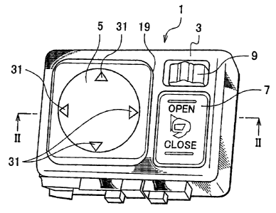
FIGS. 1 and 2 show a switch device to according to an
embodiment of the present invention. FIG. 1 is a perspective
view of the switch device, and FIG. 2 is a sectional view thereof
taken along a line II-II of FIG. 1. A switch device 1
illustrated in FIGS. 1 and 2 are, for example, to operate a right
or left door mirror of a vehicle. The switch device 1 includes a
-9-
CA 02510723 2005-06-27
push button 5 serving as a push operation body, a seesaw switch 7,
and a slide switch 9 on a switch case 3.
The push button 5 is to change and adjust the direction of
a mirror surface of a right or left door mirror upward, downward,
rightward, or leftward. The seesaw switch 7 has an open-
operation portion and a close-operation portion. Upon an
operation on one of these portions, the position of the door
mirror can be Changed to a use state or a folded state. The
slide switch 9 is subjected to a sliding operation toward right
or left, thereby switching the adjustment of the mirror surface
by the push button 5 to either one of the right and left mirrors.
The switch case 3 supports the push button 5, the seesaw
switch 7, and the slide switch 9. The switch case 3 includes a
base 11 and a cover 13 attached to the base 11 removably.
A terminal block 15 is removably mounted on the base 11.
The terminal block 15 is provided with a plurality of fixed
contacts 17 correspondingly to operations of the push button 5.
At the cover 13 side, an opening 19 is provided in which
the push button 5 is diposed. The opening 19 has a square shape
in a plane view. According to the present embodiment, the opening
19 has an approximately foursquare shape, for example. In the
-10-
õ .
CA 02510723 2005-06-27
opening 19, an engaging surface 21 is formed along the perimeter
of the opening 19 to define an inner surface of the switch case 3.
Provided around the perimeter of the engaging surface 21 is a
wall 23. The wall 23 enables to regulate a still position of the
push button 5 with respect to the opening 19. The wall 23 at a
circumferential wall 25 side of the cover 13 is defined by the
circumferential wall 25.
The push button 5 is disposed in the opening 19 of the
switch case 3, and can be operated so as to be tilted to one of a
plurality of directions by pushing an outer edge side. According
to the present embodiment, the push button 5 can be operated so
as to be tilted in one of four directions by pushing any one of
four portions. Tilting operations of the push button 5 in the
four directions correspond to in up, down, right, and left
movements of the mirror surface of the door mirror. The push
button 5 has a square shape in a plane view, typically in an
approximately foursquare shape. The push button 5 includes a
push portion 27 and a flange 29, and is formed in an
approximately hat section shape.
The push portion 27 protrudes from the opening 19, and is
provided on its upper surface with four triangular marks 31 as
-11-
CA 02510723 2005-06-27
marks for operation. The flange 29 engages in an opposed manner
with an engaging surface 21 in the switch case 3. The wall 23 is
adjacent to the outer perimeter of the flange 29, and has a
structure in which the wall 23 enables to stop the flange 29 when
the flange 29 moves to a direction along the opening 19 (such a
movement is hereinafter referred to as a "lateral movement").
Provided at the center of the bottom surface of the push
button 5 is a connector 33. To the connector 33, an operating
member 35 is removably provided. At a tip side of the operating
member 35, a rubber contact 37 supported to the switch case 3 is
provided. The rubber contact 37 has an elastic force, and an
elastic reaction force of the rubber contact 37 is exerted to the
push button 5 via the operating member 35.
Therefore, the push button 5 has a structure in which the
elastic reaction force of the rubber contact 37 causes the push
portion 27 5 to protrude from the opening portion 19, thereby
keeping the still position at which the flange 29 engages with
the engaging surface 21. Thus, the rubber contact 37 forms
elastic member that forces the push button 5 as a push operation
body to a position before pushing.
The rubber contact 37 is provided with four movable
-12-
CA 02510723 2005-06-27
contacts 39 that correspond to the triangular marks 31, which
indicate push positions. Therefore, upon pushing any one of the
marks 31 on the push button 5, the push button 5 is tilted to
cause the corresponding pushed portion to go downward, thereby
deforming the rubber contact 37 via the connector 33 and the
operating member 35. With the deformation of the rubber contact
37, the corresponding movable contact 39 comes into contact with
the fixed contact 17, thereby allowing the direction of the
mirror surface of the door mirror to be selectively adjusted
upward, downward, rightward, or leftward.
To the push button 5 and the switch case 3, a convex
portion and a concave portion are separately provided as a
supporting portion and a supported portion that can be spaced
apart from each other for rotational support and positional
regulation of the push button 5 with respect to the switch case 3
at the time of a tilting operation by a pushing at each mark 31.
FIGS. 3 to 9 are drawings for describing the convex and
concave portions. FIG. 3 is an enlarged plan view of the push
button 5, FIG. 4 is an enlarged plan view of main portions of the
push button 5, FIG. 5 is a plan view of an inner surface side of
the cover 13 of the switch case 3, FIG. 6 is a plan view of
-13-
CA 02510723 2005-06-27
positions of convex and concave portions between the switch case
and the push button, FIG. 7 is an enlarged sectional view showing
main portions taken along a line =I-V=1 of FIG. 6, FIG. 8 is a
sectional view taken along the line VIII-VIII of FIG. 6, and FIG.
9 is a sectional view after an operation of tilting the push
button of FIG. 8.
As shown in FIGS. 3 and 4, the flange 29 of the push button
5 has corner portions each provided with a convex portion 41.
The surface of the convex potion 41 is formed in a spherical
shape. The corner portions of the flange 29 are each provided
with a swelled portion 45 in a plane direction. The swelled
portion 45 is where the convex portion 41 is provided.
As shown in FIG. 5, corner portions on the inner surface of
the switch case 3 opposite to the corner portions of the flange
29, that is, corner portions on the engaging surface 11 of the
cover 13, are each provided with a concave portion 47. The
surface of the concave potion 47 has a spherical shape
corresponding to the convex portion 41. Thus, according to the
present embodiment, the convex and concave portions 41 and 47 are
each formed in a spherical shape allowing a spherical guide
without a rattle between these portions. However a rattle
-14-
CA 02510723 2005-06-27
between the spherical surfaces of the convex and concave portions
41 and 47 is allowable to a certain degree as long as the flange
29 does not make contact with the wall 23 or, even if making
contact therewith, no rubbing sound is generated.
In the above-described structure, the convex and concave
portions 41 and 47 are separately provided to the flange 29 and
the engaging surface 21, which is the inner surface of the switch
case opposite to the flange 29. Alternatively, the convex
portion 41 may be provided to the cover 13 side and the concave
portion 47 may be provided to the flange 29 of the push button 5.
FIGS. 6 and 7 illustrate the state in which the convex
portion 41 engages with the concave portion 47 with the push
button 5 being disposed in the opening 19 of the cover 13. In
FIG. 6, for the purpose of description, the concave and convex
portions 47 and 41 are represented by solid lines although they
are actually hidden by the cover 13.
With the push button 5 being disposed in the opening 19 of
the cover 13, the convex portion 41 of the flange 29 engages with
the concave portion 47 of the engaging surface 21 of the cover 13
for positional regulation. In this state, the push button 5 is
forced by the rubber contact 37, and the convex portion 41 at
-15-
CA 02510723 2005-06-27
each corner portion of the flange 29 engages with the
corresponding concave portion 47 at the corner portion of the
engaging surface 21, thereby regulating the still position with
the force of the rubber contact 37. This regulation of the still
position can reliably suppress a rattle of the push button 5.
Also, the wall 23 enables to stop a lateral movement of the push
button 5, thereby reliably suppressing a rattle of the push
button 5. FUrtheLuure, when the push button 5 is pushed for a
tilting operation, the convex portion 41 is easily removed from
the concave portion 47 so as to be spaced apart therefrom.
In the state shown in FIG. 8, when the push button 5 is
pushed at any one of the marks 31 in order to adjust the mirror
surface of the door mirror, the push button 5 is tilted with
respect to the cover 13, as shown in FIG. 9. At this tilting,
the convex portions 41 positioned at both corner portions of the
mark 31 at the pushed position are removed from the corresponding
concave portions 47 of the engaging surface 21, and the convex
portions 41 positioned at both corner portions opposite to those
of the mark 31 at the pushed position are guided in rotation by
the corresponding concave portions 47 of the engaging surface 21.
Therefore, at the time of pushing the push button 5, even
-16-
CA 02510723 2005-06-27
when a force Fsine as shown in FIG. 12 is generated, the force
Fsin0 is stopped by the convex portions 41 engaging with the
concave portions 47 as described above. Therefore, the push
button 5 does not move in the lateral direction with respect to
the opening 19, and is rotationally tilted at the same position
as shown in FIGS. 8 and 9.
As such, even when the flange 29 is close to the wall 23,
the flange 29 of the push button 5 is prevented or suppressed
from rubbing against the wall 23, thereby preventing or
suppressing a rubbing sound. Also, the feeling of rubbing can be
prevented or suppressed, thereby significantly improving the
feeling of operation.
As described above, the concave and convex portions 47 and
41 are provided at four positions corresponding to the corner
portions of the push button 5. Therefore, at whichever the four
marks 31 the push button 5 is pushed, effects that can be
achieved are similar.
In the above embodiment, the present invention is applied
to the push button 5 and the opening 19 each having a square
shape in a plane view. Alternatively, the present invention may
be applied to the push button 5 and the opening 19 each having a
-17-
CA 02510723 2005-06-27
rectangular or circular shape, for example. Still alternatively,
only the flange 29 may be formed in a square shape, and the push
portion 27 and others may be formed in a circular shape, for
example. The convex and concave portions 41 and 47 can be
arbitrary as long as these portions achieve rotational support
and positional regulation and can be spaced apart from each other.
Also, the convex and concave portions may be wedge-shape convex
and concave portions, for example. The supporting and supported
portions are not restricted to the convex and concave portions 41
and 47. Furthermore, the supporting and supported portions that
can be spaced apart from each other are not restricted to those
that can be completely removed from each other, but may be those
connected partly by an elastically-extendAble portion or the like.
The operation positions of the push button 5 are not
restricted to four positions, but may be two positions opposite
to each other, for example.
-18-