Note: Descriptions are shown in the official language in which they were submitted.
CA 02510804 2005-06-17
WO 2004/056656 PCT/NZ2003/000290
VACUUM PACKAGING MACHINE AND LOADING SYSTEM
FIELD OF THE INVENTION
The present invention relates to apparatus and a method for efficiently vacuum
packaging product packages.
BACKGROUND
l0 Vacuum packaging machines of a known type comprise a vacuum chamber
arranged to
receive unsealed product packages and operable to perform a vacuum sealing
operation
on the product packages. Typically the product packages contain products such
as meat
cuts, arranged in a bag formed by a heat-shrinkable film. After loading and
closing the
vacuum chamber, the vacuum sealing operation normally comprises vacuumisation,
sealing the mouth of the vacuumised bags, and reintroducing air into the
chamber.
Then the chamber is opened and the vacuum chamber is unloaded. The product
packages may then generally be conveyed to a heat-shrinking unit, typically a
hot water
tunnel, dip tank, hot air tunnel or other shrink activating system.
It is an obj ect of the present invention to provide an improved or at least
alternative
apparatus for efficiently vacuum packaging products which is suited for use in
an
automated production line.
SUMMARY OF THE INVENTION
In one aspect the invention comprises apparatus for packing products,
including:
a vacuum packaging machine for performing a vacuum sealing operation on
product
packages,
an upstream product information acquisition stage arranged to acquire
information
relating to one or more characteristics of the products on a product packing
line, and
1
CA 02510804 2005-06-17
WO 2004/056656 PCT/NZ2003/000290
two or more generally parallel load conveyors arranged to deliver or load
products of
different sizes into packs and into the vacuum packaging machine, by a lesser
number
of the conveyors for smaller products and a greater number of the conveyors
for larger
products.
Preferably the apparatus also includes pack opening means arranged to open the
mouth
of each pack to a controlled width across the direction of travel of the load
conveyor(s),
based on information relating to products being packed acquired at the
upstream product
l0 information acquisition stage and present the pack so that the load
conveyors) deliver
the products into the open packs which are then delivered into the vacuum
packaging
machine, or deliver the products into the open packs which are already in or
partially
entered into the vacuum packaging machine.
In another aspect the invention broadly comprises apparatus for packing
products
including:
a vacuum packaging machine for performing a vacuum sealing operation on
product
packages,
an upstream product information acquisition stage arranged to acquire
information
relating to one or more characteristics of products on a product packing line,
and
pack opening means arranged to open the mouth of each pack to a controlled
extent
based on information relating to products being packed acquired at the
upstream product
information acquisition stage, and to present the pack so that the products
are delivered
into the open packs which are then delivered into the vacuum packaging
machine, or
deliver the products into the open packs which are already at least partially
entered into
the vacuum packaging machine.
Typically the packs will be bags such as plastic bags or sacks. Typically the
packs will
be sealed at one end and unsealed at the other. The packs may be supplied to
the
2
CA 02510804 2005-06-17
WO 2004/056656 PCT/NZ2003/000290
packing opening means sequentially, as individual products such as meat cuts
approach,
from a bulk supply such as a stack or rolled stock of packs for example, or
alternatively
may be made on-line to a standard length, or to the appropriate length
tailored to the
size of individual meat cuts, by cutting and sealing bags from tube stock for
example.
Information from the product information acquisition stage on product
characteristics
such as size is used to deliver products to the packing stage by activating
selected
conveyors for the products. For example in a simple form two parallel
conveyors may
be provided, one of which carnes smaller products to the product packing stage
and
to both of which are activated to run in parallel to carry larger products to
the packing
stage. The two conveyors may have similar or different widths. In another form
three
or more parallel conveyors may carry products to the packing stage. The
conveyors
may be "centred" ie a centre conveyor may be flanked on either side by
adjacent
conveyors of a similar width which may be smaller or larger in width than the
centre
conveyor, or may be non-centred.
In a preferred form the load conveyors) are arranged to deliver products into
the packs
or bags by also telescoping or moving forward into the packs or bags to an
extent
dependent upon the size of the product ie further for longer products than for
shorter
2o products, again based on product size information previously acquired at
the upstream
product information acquisition stage.
The pack opening means will typically comprise one or more parts which insert
into the
mouth of each pack and spread the pack to a controlled extent of opening.
Fingers
inserted into the pack may open the pack to a variable extent of lift (the
height direction,
at approximately right angles to the plane of the unopened pack), or to a
variable degree
of lift combined with a fixed or variable degree of width opening, or vice
versa. Where
the degree of lift opening is controlled dependent upon the product size, the
degree of
width opening may be to an extent which is fixed, sufficient to simply take up
slack in
the bag opening, or which is also controlled dependent on the product size,
and vice
versa where the degree of width opening is the opening dimension which is
primarily
controlled relative to product size. Alternatively means may grip the pack
mouth from
3
CA 02510804 2005-06-17
WO 2004/056656 PCT/NZ2003/000290
the exterior for controlled opening of the pack, rather than inserting into
the interior of
the mouth of the bag.
The acquired information relating to the individual products such as
individual meat
cuts may include any one of dimensional information such as length
information, width
information, height information, or any combination of length, width and/or
height
information, volume or shape information, or weight information, or a
combination of
one or more of any such information.
to The acquired product information may be used to activate both the
appropriate conveyor
or conveyors dependent on product size as well as the pack opening means to
open the
mouth of the pack to a controlled width appropriate for the approaching
product and
position so that the product will be delivered by the conveyor or conveyors
aligned to
the pack mouth.
In one form the vacuum packaging machine may comprise a plurality of vacuum
chambers each arranged to receive at least one unsealed product package and
operable
to perform an independent vacuum sealing operation on the at least one product
package.
In one form each vacuum chamber has a longitudinal direction defined by a
direction of
loading of packages in to the chamber, and has a heat seal bar therein which
extends
transversely to the longitudinal direction. Having a transverse heat seal bar
in each
vacuum chamber enables the product packages to be loaded into each chamber
with
their openings transverse to the longitudinal direction. This orientation
corresponds to
the orientation of the packages as they exit most manual bagging stations or
automatic
packaging systems, which would generally be upstream of the vacuum packaging
machine.
3o The vacuum chambers may be spaced horizontally or, more preferably, may be
vertically stacked which provides a smaller footprint. In an alternative
embodiment, a
3-dimensional (horizontal/vertical) array of vacuum chambers may be provided.
4
CA 02510804 2005-06-17
WO 2004/056656 PCT/NZ2003/000290
Preferably, the machine is operable to operate one of the vacuum chambers to
perform
the vacuum/sealing operation while another of the vacuum chambers is open for
loading
and unloading.
The heat seal bar in each vacuum chamber is preferably located at the end of
the
chamber adjacent the load conveyor(s), and the unsealed product package is
preferably
loaded into the chamber with the unsealed end of the package trailing. In, one
embodiment the infeed conveyor may telescope over the heat seal bar to load
the
l0 product into the vacuum chamber with the unsealed portion of the product
package
being located over the transverse heat seal bar, and then retract out of the
chamber so
that the chamber may be closed to perform the vacuum sealing operation.
The infeed conveyors) may also be moveable generally vertically relative to
the
vacuum chambers to enable selective loading of more than one chamber.
Alternatively,
the chambers may be moveable generally vertically relative to the at least one
infeed
conveyor to enable selective loading of more than one chamber.
Each vacuum chamber preferably includes an intenzal conveyor for conveying the
product package into and out of the vacuum chamber following the vacuum and
sealing
operation. The internal conveyors) may extend under end walls of the vacuum
chamber, and for this purpose the undersurface of the belts) of the internal
conveyors)
is preferably a smooth plasticised surface so that the vacuum chamber may seal
over the
conveyor belt.
In an alternative construction, the infeed conveyor for each vacuum chamber
may be
totally enclosed within the chamber. This configuration has the advantage that
it does
not require the chamber to seal over the conveyor belting. In this
configuration the
bottom portion of the sealing assembly may retract allowing a telescoping
conveyor or
moving conveyor from the first chamber to operate at the same height as the
internal
chamber conveyor of the second chamber, eliminating any product "drop" over
the
s
CA 02510804 2005-06-17
WO 2004/056656 PCT/NZ2003/000290
sealing assembly. It will be clear to those skilled in the art that other
product
loading/conveying systems would also be applicable to the machine.
The conveyor arrangement preferably further includes at least one outfeed
conveyor
operable to convey product packages from the vacuum packaging machine. The at
least one outfeed conveyor may be moveable relative to the vacuum chambers to
enable
selective unloading of more than one chamber. Alternatively, the chambers may
be
moveable relative to the at least one outfeed conveyor to enable selective
unloading of
more than one chamber.
io
An additional feature of the conveyorised infeed, vacuum chamber, and outfeed
is that
product packages can be loaded and unloaded simultaneously.
In the most preferred embodiment, the vacuum packaging machine includes two
vertically-stacked vacuum chambers, a single infeed conveyor and a single
outfeed
conveyor, the vacuum chambers being synchronously vertically moveable between
a
loading/unloading position adjacent and between the infeed and outfeed
conveyor and
an operating position spaced from the infeed and outfeed conveyor, the machine
being
operable such that as one vacuum chamber is performing the vacuum/sealing
operation,
the other vacuum chamber is open for loading/unloading.
Preferably one product package is loaded into a selected vacuum chamber at a
time for
the vacuum sealing operation. Alternatively, the machine may be arranged to
concurrently load more than one package into a selected vacuum chamber, the
packages
being arranged transversely on the infeed conveyor and in the vacuum chamber
so that
they can be vacuum sealed concurrently.
In a further aspect, the invention comprises a method for packing products,
including:
3o acquiring information relating to one or more characteristics of products
on a product
packing line, and
6
CA 02510804 2005-06-17
WO 2004/056656 PCT/NZ2003/000290
delivering or loading products into packs and into a vacuum packaging machine
via two
or more generally parallel load conveyors, by a lesser number of the conveyors
for
smaller products and a greater number of the conveyors for larger products.
In broad terms in another aspect the invention comprises a method for packing
products
including:
acquiring information relating of one or more characteristics of products on a
product
packaging line,
machine opening the mouth of each pack to a controlled extent based on
information
relating to one or more characteristics of the products being packed acquired
at an
upstream product information acquisition stage, and delivering or loading
products into
the open packs and then into a vacuum packaging machine or into the open packs
which
are already at least partially entered into the vacuum packaging machine.
This invention may also be said broadly to consist in the parts, elements and
features
referred to or indicated in the specification of the application, individually
or
collectively, and any or all combinations of any two or more said parts,
elements or
features, and where specific integers are mentioned herein which have known
equivalents in the art to which this invention relates, such known equivalents
are
deemed to be incorporated herein as if individually set forth.
The invention consists in the foregoing and also envisages constructions of
which the
following gives examples only.
BRIEF DESCRIPTION OF THE FIGURES
A preferred embodiment of the present invention will now be described with
reference
3o to the accompanying figures, in which:
CA 02510804 2005-06-17
WO 2004/056656 PCT/NZ2003/000290
Figures 1 to 8 schematically show operation of a preferred embodiment vacuum
packaging machine including product loading system,
Figs 9 to 12 schematically show in plan view the layout and operation of one
preferred
form of load conveyor for use in loading products into packs and/or packs into
a
vacuum packaging machine,
Fig 13 shows in more detail in plan view a form of product loading conveyor
system,
Fig 14 shows the product loading conveyor system of Fig 13 in the direction of
arrow Y
of Fig 13,
Fig 15 schematically shows in side view the operation of a telescoping infeed
conveyor
for delivering products into packs,
Fig 16 schematically shows one form of pack opening means,
Fig 1 S schematically shows one form of pack opener,
2o Fig 16 shows another form of pack opener,
Fig 17 shows a further form of pack opener,
Fig 18A to 18E show operation of the pack opener of Figure 17,
Figure 19 is an end view of a preferred vacuum packaging machine
Figure 20 is a side elevation view of the vacuum packaging machine of Figure
19;
3o Figure 21 is a further side elevation view of the vacuum packaging machine
of Figure
19;
s
CA 02510804 2005-06-17
WO 2004/056656 PCT/NZ2003/000290
Figure 22 is a view of the interior of a vacuum chamber, showing a sealing
assembly ;
Figure 23 is a perspective view of the upper interior of a vacuum chamber,
showing the
details of the upper part of the sealing assembly of Figure 22;
Figure 24 is a view of the lower part of a vacuum chamber, showing details of
a lower
part of the sealing assembly of Figure 32;
Figure 25 is a perspective view of the lower part of the sealing assembly of
Figure 22;
Figure 26 shows part of a pulley arrangement for raising and lowering the
vacuum
chambers in the machine of Figure 19;
Figure 27 is an overhead end view of the machine of Figure 19;
Figure 28 is a side elevation view of the machine of Figure 19, showing a
cross-flow
valve mechanism for transfernng vacuum between vacuum chambers;
Figure 29 is a further detailed view of the cross-flow valve mechanism of
Figure 28;
2o and
Figure 30 is a fiu-ther detailed view of the cross-flow valve mechanism of
Figures 27
and 24.
DETAILED DESCRIPTION OF PREFERRED EMBODIMENT
A preferred embodiment machine comprises a vacuum packaging machine generally
indicated at 1 in Figure 1, which is described in more detail subsequently
with reference
to Figures 19 to 30, and a pack opening and product loading system generally
indicated
at 2 in Figure l, which is described in detail immediately below with
reference to
Figures 1 to 8.
9
CA 02510804 2005-06-17
WO 2004/056656 PCT/NZ2003/000290
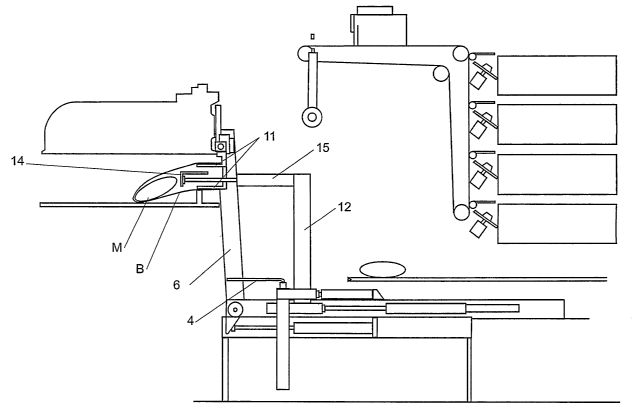
Referring to Figures 1-8, in use meat cuts such as that indicated at C are
carried by
product supply conveyor 3 towards the vacuum packaging machine 1. Meat cuts
are
delivered by the product supply conveyor 3 onto elevator plate 4 when it is in
it's
lowered position as shown in Figure 1, and are then elevated as shown in
Figures 2 and
3. Movement of the elevator plate 4 is driven by pneumatic (or hydraulic)
cylinder 5,
which is in turn carried by a moving carnage assembly 6 which moves in the
direction
of arrow J in Figure 1 on the machine bed 7. For example the moving carnage
assembly 6 may be moveably mounted to the machine bed 7 by wheels 8, and
driven by
pneumatic cylinder 9. When the product supply conveyor 3 has delivered the
product
onto the elevator plates 4 the forward telescoping end of the conveyor 3
withdraws.
An empty pack such as bag B is picked up from a bulk supply as will be further
described, the two sides of the bag mouth are separated, and the bag is
brought down
from the position shown in Figure 1 to the position shown in Figure 2 by
pivoting pack
pickup arm 9 which moves in the direction of arrow F in Figure 1. The pack
pickup
arm 9 in its upper position shown in Figure 1 picks up a fresh pack and then
pivots
down while at the same time pack presenter arm 10 carrying pack opening means
in the
form of figures or spoon plates 11 moves upwardly to the position of Figure 2.
The
partially open mouth of bag B is entered onto the fingers or spoons 11 of bag
presenter
2o arm 10 as shown. The bag presenter arm 10 having received a pack then
pivots
downwardly as shown in Figure 3. As it does so the fingers or spoons 11 are
driven
apart to open the mouth of the bag further, and preferably to a desired extent
to match
the size of the approaching meat cut C, as will be further described. Movement
of the
pack presenter arm 10 and the elevator plate 4 is co-ordinated so that the
meat cut is
presented to the pack presenter arm 10 as it pivots downwardly as shown in
Figure 3,
and in doing so enters the open mouth of the bag over the meat cut on the
elevator plate
as shown in Figure 4.
The carriage assembly 6 is then moved forward (by cylinder 9) to the position
shown in
3o Figure 5 to carry the meat cut in the open mouth of the bag on the elevator
plate, into
the open chamber of vacuum packaging machine 1 as shown. At about the same
time
product ejector carriage 12 is moved forward as indicated by arrow K in Figure
1. The
to
CA 02510804 2005-06-17
WO 2004/056656 PCT/NZ2003/000290
product ejector carriage 12 is movably mounted in the machine bed 7 and may be
driven by hydraulic cylinder 13 for example. The product ejector carriage
carries
ejector plate 14 which moves in the direction of arrow I in Figure 1 relative
to the
product ejector carriage 12, and may be driven by a cylinder 15 carried by the
product
ejector carriage 2.
Referring to Figure 6 cylinder 15 is then actuated to move the ejector plate
14 forward
to push the meat cut further into the bag, following which the ejector plate 2
withdraws,
and product ejector carriage 12 moves back - see Figure 7 - while at about the
same
l0 time the fingers or spoons 11 of the bag presenter arm 10 close together
and then
withdraw so as to leave the open mouth of the bag draped across the lower part
of a
sealing and cutting assembly within the vacuum chamber, such as a heat sealing
anvil as
will be further described. The vacuum packaging machine then closes as shown
in
Figure 8 and carnes out a vacuum and sealing operation. At about the same time
or
prior the product supply conveyor 3 operates to move the next meat cut onto
the
elevator plate 4 ready to load the next meat cut into a pack and into the next
vacuum
chamber in the same way.
As referred to above the bag presenter arm 10 includes fingers or plate-like
spoons 11
2o which insert between the separated sides of the mouth of a pack or bag, and
then move
apart to open the bag mouth, preferably to a controlled degree of height or
lift.
Optionally similar fingers may be provided on either side which move in a
lateral or
width-wise direction to open the bag to a fixed or controlled degree of width
opening.
The degree of lift may be continuously variable dependent upon the size of
each
individual product or may be stepped between a number of predetermined levels
of
opening for products within broad size ranges. For each such a size the bag
may be
opened or spread laterally to a controlled degree which again may be
continuously
variable dependent on product size, or to fixed steps of lateral opening. The
lift opening
fingers or spoons and optionally width opening fingers may be controlled by
servo
3o motors which adjust the position of the lift and lateral opening of fingers
for each~bag,
by small pneumatic cylinders, or by any other suitable mechanical arrangement.
The
extent to which the spreader fingers or spoons 11 are driven apart to open the
bag to a
m
CA 02510804 2005-06-17
WO 2004/056656 PCT/NZ2003/000290
controlled extent maybe based on information provided from an earlier machine
vision
or similar stage through which each product passes.
A control system may control operation of the machine as described above, and
may
also synchronise the arrival of individual meat cuts with the acquired
information
relating to the individual meat cuts. In another arrangement acquired
information
relating to each product may be sent directly from a machine vision stage to
the packing
and vacuuming station and retained in a database at the packing and vacuuming
station
until that meat cut has arrived, and is then used to open the bag to the
appropriate extent
io for that size of product. In a yet more sophisticated arrangement
individual meat cuts
may be tracked along a packing line so that the system can detect if any
individual meat
cut is removed from the product stream for any reason, to avoid mis-indexing
of the
meat cuts and packs, and this may be achieved by detecting and tracking the
movement
of each meat cut from one conveyor to the next. Various arrangements are
possible.
Such a product information acquisition stage (not shown) which may be a
machine
vision system beneath which individual products such as meat cuts pass on a
product
packing line, may acquire information relating to one or more characteristics
of the
individual products such as dimensional information. Dimensional information
may be
2o simple such as only one of the length or width or another single dimension
of each
product or meat cut. More preferably the machine vision system is set up to
acquire
further dimensional information indicative of the size of the meat cuts or the
volume or
shape of the meat cuts. Weight information may supplement dimensional
information
acquired by the machine vision stage.
A machine vision stage may comprise a digital camera system which "sees"
individual
meat cuts and/or a system which directs at least one beam or line from a
scanning laser
over individual meat cuts with deflection and/or reflection of laser light on
the meat cut
being seen by a camera system and the resulting information being processed to
provide
3o the dimensional and/or volume or shape information in relation to each meat
cut.
Alternatively the machine vision system may simply be a series of horizontal
and
vertical beams across the conveyor path at different heights or spacings
through which
12
CA 02510804 2005-06-17
WO 2004/056656 PCT/NZ2003/000290
the meat cuts pass, providing information to a control system as to the width
and/or
height and/or length of the meat cuts based on the number of beams broken by
each
passing meat cut. Any other machine vision system which enables the
acquisition of
information as to one or more of product length, width, size, volume, shape or
similar
may be used.
The acquired information may be supplied direct to individual electronic or
programmed controllers for one or more downstream packing and vacuuming stages
on
the packing line, or to a common control system for a packing line which also
controls
to other stages of the packing line, and synchronises the arrival of
individual products at
points along the packing line.
In an alternative form the product information acquisition stage may simply
comprise a
weighing means such as a weighing conveyor which weighs individual meat cuts
and
passes weight information for use by a controller of the pack opening means,
to open
each bag to a controlled extent depending on individual product weight.
Packs or bags may be supplied from a stack or rolled stock or alternatively
may be made
on-line by cutting and sealing bags from tubes. A range of bag or stock widths
may be
2o available in a range of materials such as oxygen barrier materials, export
grade packing
material, and so forth from which the bags may be selected as directed by the
control
system. Bags preprinted with different labeling or branding information may
also be
provided and selected from. Refernng again to Figure 1, in a preferred form
bags may
be supplied from bag magazines 22, each of which contains rolls of
prefabricated .bags
of different sizes and/or types of bags with various properties eg different
oxygen
barrier or puncture properties or printed labeling information. Alternatively
one or
more of the bag magazines 22 may be replaced by one or more on line bag making
machines (as are known in the art). As each meat cut approaches or is being
loaded, the
machine control system causes one of the bag magazines to present a bag to bag
delivery conveyor 20, of the appropriate size and/or type for the particular
meat cut.
Bag deliver conveyor 20 passes around rollers 21, and picks up the bag from
the
selected bag magazine 22 and delivers it closed mouth first to the position of
bag B in
13
CA 02510804 2005-06-17
WO 2004/056656 PCT/NZ2003/000290
Figure 1 ready for pick up by the pack pickup arm 9. Where the bags are not
printed
they may pass below printer 23 and have information printed on the bag, or
additional
information printed on the bag relating to the specific meat cut to be
packaged eg
weight or type information where the bags have already been pre-printed with
more
generic information such as branding information for example. To separate the
two
sides of the mouth of the bag ready for pick up by the bag pick up arm 9, one
or more
suction cups above and below the bag mouth may grip either side of the waiting
bag and
then move slightly apart to separate the two sides of the bag mouth. A series
of suction
cups or a longitudinally extending suction bar may be provided above and below
the
l0 bag mouth. The control system moves the suction cups towards the bag mouth
on either
side and applies suction at the appropriate time, and releases the suction
when the bag
has been picked up by the pack pickup arm 9, to allow the pack pickup arm 9 to
pivot
downwardly to enter the bag mouth onto the fingers or spoons 11 of the bag
presenter
arm 10. Alternative arrangements for separating the bag mouth may be used
however.
Preferred Conveyor Systems for Loading Products into Packs and/or into a
Vacuum Packaging Machine
Refernng to Figs 9 to 12, products of different sizes such as meat cuts M may
be loaded
into packs and/or also into a vacuum packaging machine on parallel spaced
conveyors
90.
Any one or more of the three conveyors 90 may be activated by the control
system,
dependent on the product size. For example when smaller meat cuts are
identified by
the machine vision system they are directed to a centre conveyor and only the
centre
conveyor is activated, as shown in Fig 9. The pack opening means may present a
smaller pack or a pack which is opened to a lesser extent, into which the
smaller meat
cut M on the centre conveyor is delivered. The pack opening means may align
the
packs with the centre conveyor. When the machine vision system identifies a
meat cut
of intermediate size such as indicated at M in Fig 10, more of the load
conveyors 90 are
activated to load that meat cut. Referring to Fig 11, when the machine vision
stage
14
CA 02510804 2005-06-17
WO 2004/056656 PCT/NZ2003/000290
identifies a yet larger meat cut M, all five of the load conveyors are
activated to load the
meat cut.
The two or more conveyors need not necessarily be arranged in a "centred"
configuration in which smaller meat cuts are delivered to the centre conveyor.
For
example in an alternative configuration cuts can be aligned to one side with
one, two,
or more conveyors being activated based on the size of the cut. Fig 10 shows
conveyors
to one side activated to load an intermediate size meat cut in a non-centred
system.
1o Fig 11 shows one preferred arrangement of a telescoping input conveyor
system of the
invention that may be used to load meat cuts M into open packs or bags P. The
forward
ends) of the one or more parallel load conveyors) (dependent on product size)
a
telescope into the pack which is presented to the meat cut, and then withdraw,
depositing the meat cut within the pack within the vacuum packaging machine.
Operation of the load conveyors 90 is controlled such that where smaller meat
cuts are
conveyed by a single one of the input conveyors, the open mouth of the pack is
aligned
with that input conveyor, which telescopically deposits the meat cut into the
open pack.
Where the meat cut and pack are larger, two or more of the load conveyors
telescope
together to deposit the meat cut into the open pack as described above, and
the open
2o pack is positioned laterally relative to the direction of forward movement
of the load
conveyors so that the pack is aligned with the load conveyors loading the meat
cut.
Another preferred embodiment pack opener and it's operation are shown in
Figures 17
and 18A to E. The pack opener comprises four parts herein referred to as
blades 70 and
71. The lower blades 70 are carned by mounts 72 which slidably move on shafts
73,
and upper blades 71 axe carried by mounts 74 fixed to the shaft 73. Pneumatic
cylinder
75 can move the lower blades 71 vertically. The mounts 72 carrying the lower
blades
70 are connected by shaft 76 to which the shaft 77 of the pneumatic cylinder
75 is
coupled. Figure 18C (which does not show the operating cylinder 75) shows the
lower
3o blades 70 separated from the upper blades 71, and in the lowermost position
of the
lower blades 70. Figures 18A and 18B show the lower blades 70 in their upper
most
position. The upper and lower blade pair 70 and 71 on one side and the upper
and lower
is
CA 02510804 2005-06-17
WO 2004/056656 PCT/NZ2003/000290
blade pair 70 and 71 on the other side of the pack opener can be moved
widthwise
relative to one another. Referring to Figure 4, the shafts 73 are in turn
carried by left
and right carriages 78 which are movably mounted on subframe 79. Subframe 79
also
carnes three operating cylinders 80 each having a different stroke length, on
common
shaft 81. The three cylinders together provide eight programmable widthwise
positions
in the direction of arrow W between the upper and lower blade pairs on either
side. In
an alternative form there may be four cylinders which may provide for sixteen
programmable width positions, or the cylinders may be replaced by a single
variable
stroke pneumatic or hydraulic cylinder, or again in this or other pack openers
described
to herein the cylinders 75 and 80 may be replaced for example rack and pinion
drive
systems.
Figures 18D and 18E schematically show a range of relative positions to which
the
blades 70 and 71 may be moved relative to one another. For Figure 18D shows
how the
pack opener may open the mouth of a pack of a particular width eg a 200mm
width
plastic bag, to a range of mouth open shapes, between a maximum width-minimum
height position, and a maximum height-minimum width position of the blades.
Figure
18E shows a similar range of positions to which the mouth of a larger bag eg
in 300mm
width bag, may be opened by the pack opener.
Refernng to Figures 18A and 18B, to initially separate the two sides of the
mouth of a
pack enabling the pack opener blades 70 and 71 to insert into the mouth of the
pack,
suction cups 82 may be provided above and below the bag mouth which may
operate to
grip either side of a bag and initially separate the two sides of the bag
mouth, enabling
the blades 70 and 71 of the pack opener to enter into the mouth of the bag. In
Figure
18A a bag is schematically indicated at B, held by suction cups while the
blades 70 and
71 in their minimum width minimum height position insert into the mouth of the
bag.
Subsequently the left and right blade pair 70 and 71 may move apart widthwise,
while
the suction cups are released, to release the bag from the suction cups. The
suction cups
3o then move fully away from the bag or the bag opener blades carrying the bag
may pivot
around shaft 83 (see Figures 18A to 18C) to move the bag opener carrying the
bag away
from the suction cups, and the pack opener blades may then move to one of the
16
CA 02510804 2005-06-17
WO 2004/056656 PCT/NZ2003/000290
positions shown in Figures 518 or 18E to open the pack to enable loading into
the pack
of the product to be packed, or bringing of the pack over the product to be
packed.
In preferred forms the load conveyors of Figures 9 to 14 are arranged to
deliver
products into the packs or bags by telescoping or moving forward into the
packs or bags
to an extent dependent upon the size of the product ie further for longer
products than
for shorter products, again based on product size information previously
acquired at the
upstream product information acquisition stage.
io Alternative Systems for Opening and Loading Products into Packs
Fig 15 shows another arrangement for opening and loading packs with product;
which
comprises fingers 75 which in operation insert into the mouth of each pack or
bag such
as those indicated at B, and move apart to open the bag mouth to a controlled
degree of
height or lift. Similar fingers (not shown in Fig 15) may move in a lateral or
width-wise
direction to open the bag to a fixed or controlled degree of lateral opening.
The degree
of lift may be continuously variable dependent upon the size of the individual
product or
may be stepped between a number of predetermined levels of opening for
products
within broad size ranges. For each such a size the bag may be opened or spread
laterally to a controlled degree of width which again may be continuously
variable
dependent on product size, or to fixed steps of width opening. The lift
opening fingers
and width opening fingers may be controlled by servo motors which adjust the
position
of the lift and width opening of fingers for each bag, or by small pneumatic
cylinders, or
by any other suitable mechanical arrangement. The lift and width opening
fingers may
be mounted for vertical and horizontal movement on peripheral entry frame 6 as
shown,
or again by any other suitable arrangement.
Typically products such as meat cut C in Fig 15 will approach the packing
apparatus on
a conveyor such as conveyor 177 for example. In the packing apparatus of Fig
15 the
3o entry frame 176 carrying the spreader fingers is pivotally mounted at 178
so that it can
pivot between the upper position shown in hard outline and the lower position
shown
phantom outline. Prior to or as each product approaches, the spreader fingers
enter the
m
CA 02510804 2005-06-17
WO 2004/056656 PCT/NZ2003/000290
mouth of and pick up a fresh bag or pack, and the entry frame 176 pivots
upwardly
(from the position shown in phantom outline to the position shown in hard
outline).
The spreader fingers are driven apart to open the bag to a controlled extent,
based on
information provided from the earlier machine vision or similar stage through
which the
product has passed. The open pack is thus presented to the product which is
conveyed
to the open bag, which is then caught by exit conveyor which carries the
bagged product
onward, pulling the mouth of the bag from the spreader fingers 175.
The apparatus showing in Fig 16 is similar in operation to that shown in Fig
15 except
to that the bags are brought down into the product flow from above, rather
than from
below as in the apparatus of Fig 16. In Fig 16 the same reference numbers
indicate the
same components as in Fig 15. Again entry frame 176 carries lift and width
opening
forgers in a similar arrangement to the apparatus of Fig 15. The entry frame 6
is
mounted so as to pivotally move in the direction of arrow B from position 150
at which
the spreader fingers enter the mouth of and pick up a fresh bag or pack, to
the lower
position as shown. Prior to or during downward movement the spreader fingers
175 are
driven apart to open the bag to a controlled extent, based on information
provided from
the earlier machine vision or similar stage through which the product has
passed.
Conveyor 177 has a telescoping forward end 177a which delivers the product
through
the entry frame 176 and into the open bag as the bag is brought down towards
the
telescoping conveyor end 177a extending over the exit conveyer 179, so that
the product
is entered into the bag and the bag is drawn over the product. The conveyor
end 177a
then withdraws leaving the product in the bag which is then caught by exit
conveyor
179 which carries the bagged product onward, pulling the mouth of the bag from
the
spreader fingers 175, following which the entry frame returns to pick up a
fresh bag
from bag dispenser point 150.
In the embodiments of Figs 15 and 16 the productitems move towards the pack or
bag
which is stationary or relatively stationary. In an alternative arrangement
however the
open packs or bag may be moved towards and/or drawn over the stationary or
relatively
stationary product item. It is also possible that as the product items move,
the open bag
may be moved to be drawn over the moving product item, so that the pack or bag
and
is
CA 02510804 2005-06-17
WO 2004/056656 PCT/NZ2003/000290
product item such as meat cuts are moving towards each other as the product is
entered
into the bag.
A control system may synchronise the arnval of individual meat cuts with
acquired
information relating to the individual meat cuts. Alternatively the product
information
acquisition stage and bagging station may be autonomous, and where bags are
opened
according to product weight and for example a weighing conveyor may be
positioned
immediately upstream of the bagging stage. In a preferred arrangement acquired
information relating to each product may be sent directly from the machine
vision stage
to to the packing station and retained in a database at the packing station
until that meat cut
has arrived, and is then used to open the bag to the appropriate extent for
that size of
product. In a yet more sophisticated arrangement individual meat cuts may be
tracked
along a packing line so that the system can detect if any individual meat cut
is removed
from the product stream for any reason, to avoid mis-indexing of the meat cuts
and
packs, and this may be achieved by detecting and tracking the movement of each
meat
cut from one conveyor to the next. Various arrangements are possible.
In the embodiments of Figs. 15 and 16 the spreader fingers move height-wise
(lift) and
width-wise to open the mouth of the pack to a rectangular or square shape.
This is not
2o essential and the spreader forgers or equivalent may be positioned to open
the mouth of
the pack to a non-regular shape more adapted to the shape of the product
dynamically,
as the product is loaded. A further possibility is that the spreader forgers
or equivalent
may be dynamically opened and closed as the product enters the bag. For
example for a
hump back-shaped product such as a typical meat cut,the fingers may open the
bag to a
controlled degree and then as the product is entered into the bag continue
opening the
bag as the highest part of the product passes through the bag opening, and
then begin to
close the bag as the tailing portion or the product enters the bag, and
optionally near-
fully or partially close the bag. For this purpose the spreader fingers may
grip the
periphery of the bag or pack mouth. For example a 3D image of the product may
be
3o acquired at the machine vision stage and a multiple number of spreader
forgers moved
to duplicate the shape of the product, and open the bag to the shape of the
product, as
the product is loaded. Other similar variations are possible.
19
CA 02510804 2005-06-17
WO 2004/056656 PCT/NZ2003/000290
Figures 13 and 14 show a conveyor system of the invention comprising five
parallel
conveyors. Referring to Figure 18, any one or more of the lesser width
conveyors 100
may be pivoted upwardly to the position of the conveyor indicated at U in
Figure 14, by
mechanism 101 activated by operating cylinder 103 which operates about the
primary
shaft 102 of the conveyor system. In this embodiment, where the meat cut and
pack axe
of maximum size, all of the five conveyors may be in the lower position
indicated at L
in Figure 14 to convey the meat cut, into an open pack for example. Where the
meat cut
is of lesser size, one or more of the conveyors 100 may be caused to pivot out
of the
l0 way to the upper position U so that the meat cut will be carned by a lesser
number of
the conveyors. A control system may control which combination of conveyors is
used
ie which remains at position L and which pivots to position U, dependent upon
the size
of the product, again based on product size information previously acquired at
the
upstream product information acquisition stage.
A conveyor system may be provided in place of elevator plate 4 in the system
of Figures
1 to 8, carned by pneumatic or hydraulic cylinder 5, so that ejector plate 14
is not
required to push the meat cuts into the packs.
2o As indicated previously; packs or bags may be supplied from a stack or
rolled stock or
alternatively may be made on-line by cutting and sealing bags from tubes. A
range of
bag or stock widths may be available in a range of materials such as oxygen
barner
materials, export grade packing material, and so forth from which the bags may
be
selected as directed by the control system. Bags preprinted with different
labelling or
branding information may also be provided and selected from.
Preferred Form Vacuum Packaging Machine
With reference to Figures 19-30, a preferred embodiment vacuum packaging
machine is
3o indicated generally by reference numeral 1, which may be the vacuum
packaging
machine in Figures 1 to 8, is now described in detail. The vacuum packaging
machine
includes upper and lower vertically stacked vacuum chambers 203a, 203b, which
are
CA 02510804 2005-06-17
WO 2004/056656 PCT/NZ2003/000290
vertically moveably mounted between columns 205. Mounted adjacent the tops of
the
columns 205 is a drive mechanism 207 for the vacuum chambers 203a, 203b, the
drive
mechanism being described in further detail below with reference to Figures 26
and 27.
An electronic control system ~ controls operation of the machine 1, and a
keypad/monitor 10 is provided to enable a user to program the control system.
Each vacuum chamber 203a, 203b includes a bed 9 and a chamber hood 11. The
beds
9 are synchronously vertically movably mounted between the columns 205, and
each
l0 chamber hood 211 is vertically moveable relative to the respective bed 209.
The
chamber hoods 211 are moved via pneumatic rams 212. Alternative drive means
could
be used such as hydraulic rams or mechanical means including one or more cams
driven
by a motor or motors to move the chamber hoods..
Each vacuum chamber has a sealing assembly 215 therein, which will be
described in
more detail below with reference to Figures 22 to 25. The bed 209 of each
vacuum
chamber includes a conveyor 213 which operates to position products in the
vacuum
chamber during loading, and to convey packaged product out of the chamber
after it has
been vacuum sealed, the direction of travel of the conveyor 213 defining a
longitudinal
2o direction of the vacuum chamber.
A conveyor arrangement is provided to load/unload product packages to/from the
vacuum chambers. The conveyor arrangement includes an infeed conveyor 217 to
load
product packages into the vacuum chambers. The operation of the infeed
conveyor 217
will be described in further detail below. An outfeed conveyor (not shown) is
also
provided to remove packaged product from the machine following sealing.
As can be seen from Figures 19 to 21, the vacuum chambers are moveable
together
between a lower position (shown in Figures l and 2) wherein the upper chamber
203a is
3o adjacent the infeed conveyor 217 for loading/unloading and an upper
position (shown in
Figure 21) wherein the bed of the lower chamber 203b is adjacent the infeed
conveyor
217 for loading/unloading. While one of the vacuum chambers is in the
21
CA 02510804 2005-06-17
WO 2004/056656 PCT/NZ2003/000290
loading/unloading position, the other chamber is in an operating position to
perform a
vacuum sealing operation on the packages) contained therein. Therefore, the
operating
position for the upper vacuum chamber 203a is above the level of the infeed
conveyor,
while the operating position for the lower vacuum chamber 203b is below the
level of
the infeed conveyor.
Having one of the vacuum chambers open for loading/unloading while the other
of the
vacuum chambers is performing the vacuum sealing operation results in a
reduced cycle
time over that provided by a conventional vacuum packaging machine.
io
As can be seen from Figures 22 to 25, the sealing assembly 215 in each vacuum
chamber includes an upper part 215a and a lower part 215b. The sealing
assembly 215
extends transversely to the longitudinal direction of the vacuum chamber, and
therefore
to the direction of travel of product packages through the chamber. This
enables the
i5 product package to be delivered to the vacuum chamber with its unsealed
portion
trailing, which is the orientation in which the product package would exit
from prior
bagging/wrapping stations.
The upper part 215a of the sealing assembly includes a pair of upper spreaders
219a, a
2o heat sealing anvil 221, a puncturing device having a plurality of piercing
knives (not
shown), and a clamping device 223 having a series of clamping pins 225. The
lower
part 215b of the sealing assembly includes a pair of lower spreaders 219b
which are
complementary to the pair of upper spreaders 219a, a heat sealing bar 227, and
a lower
clamp bar 229.
In this particular embodiment, the spreading operation is as follows. The
spreaders
219a, 219b are operable to grip and spread the unsealed part of the product
package
prior to heat sealing. As will be apparent from the Figures, as the upper 219a
and lower
219b spreaders are brought together, they move outwardly by virtue of the
angled slots
220a and pins 220b extending therethrough. The spreaders function in a similar
way to
those described in PCT Publication No. WO 02110019, the disclosure of that
publication
being incorporated herein by reference, and will not be described further
here.
22
CA 02510804 2005-06-17
WO 2004/056656 PCT/NZ2003/000290
Alternative spreading systems are also envisaged. In one alternative, an air
"curtain"
provided by a series of small air jets will be provided to blow.the unsealed
package neck
flat over the seal bar.
A ftuther embodiment would be to restrict the air flow out of the product
package
during the vacuuming process and to use the resulting back pressure created to
spread
the neck of the package over the heat seal bar. This restriction may take the
form of a
bar spaced a fixed distance above the heat seal bar or alternatively a lightly
spring
loaded or gravity bar.
These embodiments are examples only, and other automatic spreading systems are
envisaged.
i5 The clamping pins 225 and lower clamp bar 229 (which would generally be
made from
a resilient material such as rubber) maintain the unsealed portion of the
package in the
spread configuration, and provide tension on the product package such that it
can be
pierced. When the puncturing device is actuated, the knives (not shown) pierce
the
package. The puncturing device forms small apertures in the product package.
During
loading of the product package into the vacuum chamber, it is feasible that
the trailing
unsealed portion of the package may be located such that it will be clamped
under the
end wall of the vacuum chamber hood 211 when it is closed. The apertures
formed by
the puncturing device ensure that any air in the product package may still be
evacuated
if this should occur.
The heat seal anvil 221 is operable to push against the heat seal bar 227 with
the
unsealed portion of the product package therebetween, applying a current to
the heat
seal bar and sealing the product package.
3o Although not shown in the Figures, a cutting device will be provided to cut
the product
package between the heat seal bar 227 and the puncturing device. The preferred
cutting
23
CA 02510804 2005-06-17
WO 2004/056656 PCT/NZ2003/000290
device is a serrated knife, which is arranged to move downwards from above to
shear
the product package.
Although not shown in the Figures, the machine includes a scrap removal device
to
remove the cut-off portions of the product package from the machine. The
preferred
scrap removal device comprises a "push-pull" system. A series of air jets are
provided
on the top front face of the heat seal bar. After the unused product package
neck has
been cut and the chamber opens, the cut portion of the neck will be supported
on the
clamping bar 229. When the chamber opens this clamping bar will drop down to
its
io home position while the air jets are simultaneously activated. This action
will blow the
severed bag neck toward a suction system which is mounted below the nose
roller of the
telescoping infeed conveyor 217. Advantageously, a second set of air jets may
also be
provided along the bottom of the heat seal bar, just above the internal
conveyor 213, to
create a full air curtain blowing toward the suction system. A significant
advantage of
this product loading/chamber system is the relatively small distance between
the air jet
and the suction system (approximately 100mm). In a conventional rotary system
the
scrap has to be blown transversely across a gap of approximately 600mm. Other
means
of removing scrap could be provided.
2o The belt of the conveyor 213 extends under the lower part of the sealing
assembly 215b,
and around the outer ends of the bed 209 of the vacuum chamber. For this
purpose, the
undersurface of the conveyor belt comprises a smooth surface (relative to a
conventional cloth surface), for example a smooth plasticised surface, such
that the
vacuum chamber can seal over the belt.
In order to deliver the product package over the lower part 215b of the
sealing
assembly, the infeed conveyor has a telescoping portion 217a. During loading
of an
open vacuum chamber, the telescoping portion 217a extends over the lower part
215b of
the sealing assembly, and is operated to drop the body of the product package
onto the
3o conveyor 213 on the bed 209 of the vacuum chamber. The trailing unsealed
portion of
the packaged product will remain located on the telescoping portion 217a of
the infeed
conveyor. As the telescoping portion 217a is retracted away from the vacuum
chamber
24
CA 02510804 2005-06-17
WO 2004/056656 PCT/NZ2003/000290
so that the vacuum chamber can be moved and closed, the trailing unsealed
portion of
the product package will drop onto the lower part 215b of the sealing
assembly, so that
the unsealed portion can be spread and sealed. The sealing assembly 215 is
relatively
low profile to mininv.se the product drop distance as the telescoping portion
217a of the
conveyor is extended into the vacuum chamber.
In this embodiment, the vertical position of the vacuum chambers is adjusted
by means
of a drive mechanism 207 comprising a cable and pulley system as shown in
Figures 26
and 27. The vacuum chambers are suspended by four cables 231 which extend
to downwardly to the vacuum chamber beds 209 adjacent each column 205 of the
machine, not all of the cables being visible in the Figures. A triple
arrangement of
pulleys 233 is provided adjacent each corner of the machine. A main drive bed
235 is
drivable in a horizontal plane as indicated by Arrow A in Figure 9, and at
each corner
one pulley 233a is rotatably attached to the main drive bed 235, while the
other two
pulleys 233b, 233c are rotatably attached to a stationary framework 237. One
end of
each cable 231 is operably attached to the vacuum chamber beds 209, while the
other
end of each cable is attached to the framework 237 as indicated by reference
numeral
239.
2o By virtue of the above configuration of pulleys and cables, horizontal
movement of the
drive bed 235 results in synchronized raising or lowering of the vacuum
chamber beds
209. The pulley configuration is such that horizontal movement of the drive
bed 235
results in a vertical movement of the vacuum chambers of double the magnitude.
For
example, a top stroke of the drive bed 235 of 400mm results in a vertical
movement of
the vacuum chambers of 800mm. However, this 2:1 ratio of vacuum chamber
movement versus drive bed movement requires twice the power that would be
required
for a 1:1 ratio.
To compensate for this, 2 constant pressure cylinders 241a, 241b axe provided
to
3o counterbalance the weight of the vacuum chambers. The constant pressure
cylinders
may be hydraulic cylinders, but in this preferred embodiment are pneumatic
cylinders.
These cylinders 241a, 241b are isolated with their own pressure vessels, which
in this
2s
CA 02510804 2005-06-17
WO 2004/056656 PCT/NZ2003/000290
embodiment are the vertical columns 205 of the machine. The cylinders 241 a,
241b
hold the vacuum chambers in equilibrium, meaning that a lesser amount of force
is
required to vertically move the vacuum chambers than would otherwise be
required.
A further cylinder 243 drives the bed 235 movement and thereby the vertical
movement
of the vacuum chambers 203a, 203b. By virtue of the constant pressure
cylinders 241a,
241b counterbalancing the weight of the vacuum cylinders, only 14% of the
compressed
air which would otherwise be required to vertically move the vacuum chambers
is
needed, resulting in energy savings. More importantly, as the two cylinders
241a, 241b
l0 which counterbalance the weight of the pressure vessels are isolated with
their own
pressure vessels 205, in the event of mechanical failure or sudden loss of air
supply, the
vacuum chambers 203a, 203b will not crash down, resulting in improved safety.
The vacuum packaging machine may optionally include a cross-flow valve
mechanism
is as indicated generally by reference numeral 245 in Figures 28 to 30. The
purpose of the
cross-flow valve mechanism is to transfer pressure from a recently-loaded
vacuum
chamber to a recently-evacuated vacuum chamber.
As mentioned above, the chamber hoods 211 are moved via pneumatic rams 212.
Once
2o the vacuum sealing has occurred in a vacuum chamber, and 1/a atmosphere
pressure has
been transferred to the evacuated chamber, an opening force is applied by the
rams 212.
Once the vacuum is removed from the chamber, the vacuum hood opens under
force.
Method of Operation of Preferred Form Vacuum Packaging Machine
The vacuum packaging machine 201 is typically located downstream from an input
conveyor system and/or system for loading products into packs as previously
described,
which may deliver unsealed product packages to the infeed conveyor 217 shown
in
many of Figures 19 to 30, or directly into the open vacuum chambers) as in the
system
of Figures 1 to 8, the packages being oriented such that the unsealed portion
of each
package is trailing.
26
CA 02510804 2005-06-17
WO 2004/056656 PCT/NZ2003/000290
For the purpose of explanation, presume that the lower vacuum chamber 203b is
in the
lower operative position and is presently vacuum sealing a product package
therein, and
the upper vacuum chamber 203a is open and adjacent the infeed conveyor 217,
ready
for loading.
The infeed conveyor 217 is actuated such that the telescoping portion 217a
extends over
the sealing assembly 215 and is operated to place a product package onto the
moving
conveyor 213 on the bed of the vacuum chamber 203a. As the telescoping portion
217a
of the infeed conveyor 217 is retracted from within the vacuum chamber, the
trailing
1o unsealed portion of the product package falls onto the sealing assembly. ~
The
telescoping conveyor is equipped with a sensing means to detect the trailing
edge of the
product and place it just in front of the sealing assembly 215. In a preferred
embodiment, the detecting means is a capacitive sensor mounted in the bed of
the
telescoping conveyor 217.
The hood 211 of the upper vacuum chamber 203a can then be closed and %2
atmosphere
pressure is transferred to the recently evacuated lower vacuum chamber as
described
above with reference to Figures 28 to 30. The chambers will move to their
upper
positions, and the remaining air will be evacuated from the lower chamber
203b, the
chamber then being opened and the packaged product unloaded while the new
product
package is simultaneously loaded.
In the upper vacuum chamber 203a, the unsealed portion of the product package
is
spread by the spreading system. The puncturing device is then actuated, such
that
knives pierce the unsealed portion of the product package while the clamping
pins 225
hold it in the spread configuration against the clamp stop 229. The spreader
bars 219
are then released, and the vacuum chamber 203a is evacuated, through the cross-
over
and vacuum techniques previously described, thereby evacuating any air from
the
product package through its unsealed portion andlor the pierced apertures.
The heat seal anvil 221 then pushes against the heat seal bar 227, heat
sealing the
package therebetween. The cutting device then shears the scrap portion of the
product
2~
CA 02510804 2005-06-17
WO 2004/056656 PCT/NZ2003/000290
package between the heat seal bar 227 and the puncturing device. The anvil 221
is then
moved away from the heat seal bar 227. When the chamber moves to the
loading/unloading position and opens, the packaged product and the scrap cut-
off
portion of the package will be released. The air curtain and suction are then
actuated to
remove the scrap from the vacuum chamber.
In the meantime, the lower vacuum chamber 203b will have already been loaded
with a
further unsealed product package, and %2 atmosphere pressure is again
transferred
between the vacuum chambers as described above. The cycle repeats, with the
vacuum
1o chambers moving to their lower positions such that the lower chamber is in
the
operative position and the upper chamber is in the loading/unloading position.
While specific embodiments of the invention have been described above,
modifications may be made thereto without departing from the scope of the
invention:
While the vacuum packaging machine shown in the Figures includes two
vertically-
spaced vacuum chambers, it will be appreciated that 3 or more vacuum chambers
may
be provided. In addition or alternatively, the vacuum chambers could be
horizontally
2o spaced, or a three ~ dimensional (vertical/horizontal) array of vacuum
chambers may be
provided
While the embodiments of the machine described above have the vacuum chambers
being vertically moveable, alternatively the infeed conveyor 217 and outfeed
conveyor
(not shown) could be vertically moveable and the vacuum chambers fixed.
Further,
more than one of each of the infeed and outfeed conveyors may be provided to
provide
a system having higher capacity.
The preferred embodiments described above load and seal one product package at
a
3o time. However, it will be appreciated that the infeed conveyor and vacuum
chambers
could be configured to load and vacuum seal two or more packages situated side-
by-
side.
2s
CA 02510804 2005-06-17
WO 2004/056656 PCT/NZ2003/000290
The foregoing describes the invention including the preferred forms thereof.
Alterations
and modifications as will be obvious to those skilled in the art are intended
to be
incorporated in the scope hereof.
29