Note: Descriptions are shown in the official language in which they were submitted.
CA 02510839 2005-06-27
- =
METHOD AND APPARATUS FOR PROVIDING ECONOMIC ANALYSIS OF
POWER GENERATION AND DISTRIBUTION
TECHNICAL FIELD
[0001] This patent relates generally to computer software, and more
particularly to
computer software used in electric power generation and distribution systems.
=
BACKGROUND
[0002] Almost every aspect of life in the twenty-first century involves
the use of
electric power. However, most users of electricity do not realize that, before
electricity
reaches their premises, it travels through a complex network of electric power
generation and
distribution systems. The complexity of power generation and distribution is
frequently
underscored by blackouts, such as those that occurred over most of the
northeastern United
States and Canada on August lztth and 15th of 2003, which make it clear that
the various
processes and systems involved in the generation and the distribution of
electricity require
very careful planning.
[0003] In the United States, electric power generation and distribution
was
traditionally highly regulated by federal government agencies, such as the
Federal Energy
Regulatory Committee (FERC), as well as by utility commissioners of various
states. These
regulating bodies set performance standards and requirements for the
generation and the
distribution of electric power for the utility companies (hereinafter referred
to as "utilities")
which generated and distributed electric power. For example, these regulating
bodies
specified the requirements for real power at various points on the electric
distribution
systems. In response to the specified requirements, the utilities determined
how much
electricity to produce, where to produce it, and how to distribute it.
(0004) Utilities generate electricity using various types of power
generators, which
may be categorized depending on the energy used to generate electricity, into
thermal,
nuclear, wind, hydroelectric, etc., generators. Each of these various types of
generators
operates under different sets of constraints. For example, an output of a
thermal generator is
a function of the heat generated in a boiler, wherein the heat generated per
hour is constrained
by the amount of fuel that can be burned per hour. Additionally, the output of
the thermal
generator may be limited by various environmental regulations that specify the
maximum
CA 02510839 2005-06-27
output of certain hazardous gases that can be emitted by the thermal power
generator.
Similar types of constraints exist with other types of power generating
systems.
[0005] Once the utilities received the requirements for real power to be
delivered, the
utilities determined which generation unit to use at what level. In making
this determination,
the utilities took into consideration the constraints on each of the available
power generators.
Moreover, to minimize the cost of power generation, the utilities typically
tried to find the
optimum combination of power generation using any of a number of sophisticated
mathematical and forecasting models available for planning the generation of
electricity.
Specifically, computer programs generally known as economic dispatch programs
were
available to help utilities make decisions related to the operation of
electric generators based
on real power requirements.
[0006] As is well known, electric power includes both real power, which is
given in
megawatts (MWs), and reactive power, which is given in mega volt-amperes
reactive
(MVARs). Because, utilities traditionally received requirements for electric
power in real
power only, traditional economic dispatch programs determined optimum
operating solutions
only in terms of real power. As a result, these programs allowed utilities to
determine
optimal operation of various generators based on a specified real power, but
did not take into
account the reactive power requirement. However, it is necessary to keep a
certain level of
reactive power on the electric distribution grids to avoid damage to
transformers and other
electrical distribution equipments. As a result, utilities still have to
generate and distribute at
least some reactive power. In the past, because the levels of reactive power
were not
mandated by the regulators, reactive power levels on grids were maintained
mostly based on
mutual understandings between various utilities and loosely defined best
practices for power
generation. Moreover, because the rates charged by utilities for power were
traditionally
highly regulated, and were generally tied to the cost of producing the
electric power, utilities
generally did not pay much attention to the cost of generation and delivery of
the reactive
power, as the utilities could easily pass on the added cost of producing the
reactive power to
their customers.
[0007] However, over the last couple of decades there has been
considerable de-
regulation and restructuring within the electric power industry of the United
States, which has
substantially increased competition among utilities and made utilities more
aware of their
2
CA 02510839 2005-06-27
cost structures. In particular, due to increased competition, the utilities
can no longer
automatically charge their customers higher prices because of higher
production costs. As a
result, utilities have become more conscious of the costs associated with
generating and
distributing both real electric power and reactive electric power, and are
less likely to provide
reactive power to properly maintain distribution grids without being
adequately compensated.
[0008] In this environment, to maintain the necessary level of reactive
power on
distribution grids, the North American Electric Reliability Council (NERC), a
utility industry
trade group, has started providing specifications for levels of reactive power
to be maintained
by utilities. As a result, when a utility is making the determination as to
which generator
technology to use for generating electricity, the utility has to take into
account not only the
real power to be produced, but also the reactive power to be produced.
[0009] Unfortunately, the task of optimizing the production of both real
power and
reactive power is highly complex, due to the relationships between the two,
and none of the
various economic dispatch programs available on the market allows optimizing
the
production of both real power and reactive power.
BRIEF DESCRIPTION OF THE DRAWINGS
[0010] Fig. 1 illustrates a block diagram of a power distribution system;
[0011] Fig. 2 illustrates a block diagram of a power generation plant;
[0012] Fig. 3 illustrates a flowchart of an example economic dispatch
program used
by the power generation plant of Fig. 2;
[0013] Fig. 4 illustrates a flowchart of an example mathematical solver
used by the
economic dispatch program of Fig. 3;
[0014] Fig. 5 illustrates a block diagram of an electric power plant using
thermal
power generators;
[0015] Fig. 6 illustrates a reactive capability curve of a combustion
turbo-generator;
and
[0016] Fig. 7 illustrates a reactive capability curve of a steam turbine
generator.
3
CA 02510839 2005-06-27.
DETAILED DESCRIPTION
0017] Generally speaking, an economic dispatch program operates as
described
herein to allocate a load demand of a power system among various available
power
generation resources. An example of such an economic dispatch program
allocates a load
demand of a power plant to various power generators, wherein the load demand
specifies the
total real power requirements as well as the total reactive power requirements
of the power
plant. The economic dispatch program may use various capacity limits
associated with the
generators, including reactive capability curves of one or more generators,
which provide
relationships between the power factors of the generators, the real power
produced by the
generators and the reactive power produced by the generators. An alternative
example of an
economic dispatch program operates to allocate a load demand of a power grid
to various
power plants, wherein the load demand specifies the real power requirements as
well as the
reactive power requirements of the power grid, and wherein one or more power
plants has
reactive capacity limits exhibited by, for example, reactive capability
curves.
[0018] Fig. 1 illustrates a power distribution system 10 having a power
grid 12
connected to a load grid 14. The power grid 12 may transmit both real power,
measured in
megawatts (MWs) and reactive power, which is a product of the voltage and the
out-of-phase
component of an alternating current, and is measured in mega volt-amperes
reactive
(MVARs). The example load grid 14 of Fig. 1 may provide power to various
industrial and
residential customers who use power consuming devices, such as air
conditioning units,
electrical motors, lights, appliances, etc. In particular, the load grid 14
may provide real
power to devices such as light bulbs, etc., and provide both real power and
reactive power to
devices such as electric motors, transformers, etc. As a result, it is
necessary that the power
grid 12 maintains a certain level of real power and reactive power available
on the load grid
14 at all times.
[0019] As indicated in Fig. 1, the power grid 12 may also be connected to
one or
more utility grids 16, 18. In this example, the utility grid 16 is connected
to a second power
grid 20, and the utility grid 18 is illustrated as being formed of one or more
power plants 22-
4
CA 02510839 2005-06-27
-
=
26, which may include any of various types of power plants, such as nuclear
power plants,
hydroelectric power plants, thermal power plants, etc. Additionally, each of
the power plants
22-26 may include any number of individual power generators. As discussed
above, the
operation of the utility grid 18 can be highly complex. As a result, to
maintain the utility grid
18 running smoothly, it is necessary that each of the power plants 22-26 be
managed with
very high precision. Moreover, it is desirable that an operator of the utility
grid 18 ensure
that the utility grid 18 is able to maintain and provide real power and
reactive power at all
points throughout the utility grid 18 in a manner that minimizes the total
cost of the utility
grid 18. To accomplish such an optimal operation, the utility grid 18 may use
an economic
dispatch program, like the one described herein, which takes into
consideration both the real
power and the reactive power required on the utility grid 18, the power grid
12 or the load
grid 14, to allocate required load demands between the powerplants 22-26.
[0020] At the plant level, each of the plants 22-26 faces the
challenge of operating
one or more power generators so that each of the power plants 22-26 can meet
its respective
power demand with sufficient accuracy as well as at the least possible cost.
In this context,
an operator of any of the power plants 22-26 may use an economic dispatch
program to
allocate the required load demands between various power generators. In this
manner, an
economic dispatch program can be used at various levels within the power
distribution
system 10, such as at the utility grid level, at the plant level, at a
generator level, etc.
Irrespective of the level at which an economic dispatch program is used, this
program
allocates required load demands between various available resources in some
optimal
manner.
[0021.] Fig. 2 illustrates a block diagram of a power plant 100 that
may use an
economic dispatch module 102 to allocate a load demand 104 among various power
generators 106-110. The load demand 104 may specify one or more of the amount
of real
power to be delivered by the power plant 100, the amount of reactive power to
be delivered
by the power plant 100, and time and place of the delivery of the real and/or
the reactive
power. The economic dispatch module 102 may use various information associated
with the
generators 106-110, such as the availability, the operating condition and the
efficiency of
each of the generators 106-110, in determining how to best allocate the load
demand 104
among the generators 106-110. If desired, the economic dispatch module 102 may
be
CA 02510839 2005-06-27
=
implemented as software stored on a memory of a computer and operable on a
controller of
the computer, as hardware, as firmware or as any combination thereof.
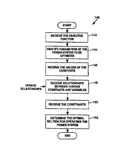
[0022) Fig. 3 illustrates a flow chart of an example economic dispatch
program 140
that may be implemented by the economic dispatch module 102. Generally
speaking, the
economic dispatch program 140 determines the allocation of the load demand 104
among
various power generators 106-110 by solving an objective function, which may
be provided
to the economic dispatch program 140 by the administrator of the power plant
100 to
determine an optimal operation point of the plant. To perform such an
optimization, the
economic dispatch program 140 receives various information about the power
plant 100, such
as parameters used to define the operation of the plant 100, values of some of
these
parameters, relationships between these parameters including reactive
capability curves of the
various generators used in the plant 100, and constraints on the operation of
the power plant.
[0023] Specifically, a block 142 receives an objective function for the
power plant
100, which is to be optimized using the economic dispatch program 140. An
example of such
an objective function may specify the total cost of producing a given amount
of real power
and a given amount of reactive power as a function of the amount of fuel
necessary to
generate the power. In an alternate implementation, the objective function may
specify total
emissions during production of a given amount of real power and a given amount
of reactive
power as a function of the amount of emissions per a unit of fuel used in
generating the
power. Of course, any other desired objective function may be used. The block
142 may
receive the objective function in any desired manner, such as in the form of
an entry in a
spreadsheet stored on the economic dispatch module 102, as a series of
selections on a
graphical user interface (GUI) based menu presented to the administrator, etc.
[0024] Upon receiving the objective function, a block 144 identifies
various
parameters used to define the operation of the power plant 100. Typically,
these parameters
are specified or used in the objective function, and the values of one or more
of these
parameters are varied to find the optimal value of the objective function.
Generally speaking,
the economic dispatch program 140 treats some of these parameters as constants
whose
values cannot be altered by the economic dispatch program 140, some of these
parameters as
controllable or manipulated variables whose values may be controlled by the
economic
6
CA 02510839 2005-06-27
=
=
dispatch program 140, and some of these parameters as dependent variables
whose values are
to be determined by the economic dispatch program 140.
[0025] Generally speaking, the objective function of the plant 100
is given as an
equation including one or more parameters of the plant 100, wherein values of
some of these
parameters may be obtained by solving one or more relationships specifying the
operation of
the plant 100 including relationships specified by the reactive capability
curves of the various
generators used in the plant 100. The economic dispatch program 140 may
determine which
parameters are to be treated as constants, as manipulated variables or as
dependent variables
based on the objective function received by the block 142. The economic
dispatch program
140 may also make such determinations using other information about the power
plant 100,
such as a database file stored in the economic dispatch module 102 wherein the
database file
has various objects, with each object identifying different equipment within
the power. plant
100. For example, if the objective function specifies the total cost of
operating the power
plant 100, the economic dispatch program 140 may treat the cost of fuel, the
cold gas
generator temperatures, the cold gas generator pressures of the generators 106-
110, etc., as
constants. In this case, the economic dispatch program 140 may also treat the
amount of real
power and the amount of reactive power, as specified by the load demand 104,
as constants
when determining the optimal operating point for the power plant 100.
[0026] In an alternate example, if the objective function
specifies the total emission of
a pollutant gas by the power plant 100, the economic dispatch program 140 may
treat the
emission of NOx per unit fuel used by the power plant 100 as a constant and
the cost of fuel
as a controlled variable (value of which may vary based on the type and
quality of fuel used).
Moreover, even though a given implementation of the economic dispatch program
140 treats
a particular parameter as a constant, an alternate implementation of the
economic dispatch
program 140 may treat that particular parameter as a manipulated variable or
as a dependent
variable.
[0027] Examples of various manipulated variables for the power
plant 100 include the
rates of fuel flows into the generators 106-1101 the operating power factors
of the generators
106-110, etc. Generally speaking, manipulated variables are those that can be
changed or
altered within the plant 100 to specify different operating points of the
plant 100. A person of
ordinary skill in the art will know that some of the variables treated as
manipulated variables
7
CA 02510839 2005-06-27
within a given implementation of the economic dispatch program 140 may be
treated as
dependent variables in an alternate implementation of the economic dispatch
program 140,
while some of the variables treated as dependent variables within a given
implementation of
the economic dispatch program 140 may be treated as manipulated variables in
an alternate
implementation of the economic dispatch program 140.
[0028] Upon determining which parameters are to be used to define the
operation of
the power plant 100, a block 146 receives values of the various constants. The
economic
dispatch program 140 receives values of some of the constants, such as the
amount of real
power and the amount of reactive power to be produced by the power plant 100,
from the
load demand 140. Generally, a user may provide values of some of the
constants, such as
cost of gas used by the generators 106-110, the heating value of the fuel,
etc. In an alternate
implementation, the economic dispatch module 102 may be communicatively
connected to a
power plant control system that supplies values for various constants such as
the cost of fuel,
the cost of NH3, etc., to the economic dispatch program 140. The economic
dispatch
program 140 may also store the values of the various constants at a periodic
rate, in response
to an instruction from the user, or based on other predetermined criteria,
into a memory of the
economic dispatch module 102.
[0029] A block 148 determines relationships between the various
parameters
identified by the block 142, including relationships specified by the reactive
capability curves
of the generators 106-110. Such relationships may define values of various
dependent
- variables as functions of one or more of the parameters. An example of
such a mathematical
relationship is a function that defines the value of the heat generated by the
generator 106 as a
function of the rate of fuel flow in the generator 106 and as a function of
the heating value of
the gas flowing through the generator 106. Yet another example of such a
relationship is a
reactive capability curve of the generator 108, which provides the value of
reactive power
generated by the generator 108 as a function of the cold gas temperature and
as a function of
the cold gas pressure of the generator 108. Of course, any other known or
desirable
relationship may be used instead of or in addition to the relationships
enumerated herein.
[0030] The economic dispatch program 140 may receive the various
relationships
from a user in the form of a spreadsheet, from a database file stored on the
economic dispatch
module 102 wherein the database file has various objects, each object
identifying an
8
- -
CA 02510839 2005-06-27 -
= õ
=
equipment within the power plant 100, etc, or in any other desired manner..
Alternatively, a
plant control system, which may be communicatively connected to the economic
dispatch
module 102, may provide one or more such relationships to the economic
dispatch program
140. Furthermore, as shown at the block 148 of Fig. 3, the economic dispatch
program 140
may update these relationships based on a periodic basis or based on any other
predetermined
criteria.
[0031] Next, a block 150 identifies various constraints on the operation
of the power
plant 100. An example of a constraint that may be used is that the total
reactive power
generated by all of the generators 106-110 must be equal to the amount of
reactive power
required to be produced by the power plant 100, as specified by the load
demand 104.
Another example of a constraint is that the fuel flow into each of the
generators 106-110
cannot be less than zero. The economic dispatch program 140 may receive the
various
constraints from a user in the form of a spreadsheet, from a database file-
stored on the
economic dispatch module 102 wherein the. database file has various objects,
each object
identifying an equipment within the power plant 100, or in any other manner.
Alternatively,
a plant control system, which may be communicatively connected to the economic
dispatch
module 102, may specify one or more such constraints to the economic dispatch
program 140
[0032] Subsequently, a block 152 determines an optimal solution for the
operation of
the power plant 100 by solving the various relationships to obtain an optimal
solution of the
objective function received by the block 142. In determining the optimal
solution, the
economic dispatch program 140 generally uses the values of the various
parameters as
identified by the block 144, the values of the constants as determined by the
block 146, the
relationships among the various parameters as defined by the block 148, the
constraints as
identified by the block 150. In particular, the economic dispatch program 140
varies the
manipulated variables in some systematic manner to identify a set of dependent
variable
values which result into an optimal value for the objective function.
(00331 Fig. 4 illustrates a flowchart of a program (generally known as
solver) 160 that
may be used to solve the objective function of the power plant 100 subject to
the various
constraints of the power plant 100. The example solver 160 determines the
optimal solution
for the objective function by using an iterative algorithm, generally known as
the
evolutionary algorithm, wherein a set of candidate solution points within the
constraints are
9
=
CA 02510839 2005-06-27
selected, a set of localized solutions corresponding to the set of candidate
solution points is
obtained and one of the set of localized solutions is selected as the optimal
solution of the
objective function.
[ON Specifically, a block 162 identifies a set of candidate solution
points for the
objective function, wherein each of the candidate solution points is
determined by a set of
manipulated variables defining an operating point for the power plant 100. The
block 162 '
may determine the set of candidate solution points by analyzing data regarding
past operation
of the power plant 100, by obtaining these solution points from a model or a
user, etc. If
=
desired, such data may be stored in a database located on the economic
dispatch module 102.
[0035] A block 164 solves the objective function for one of the set of
candidate
solution points and stores an initial value of the objective function. During
the solving
process, the block 164 uses one or more of the relationships identified by the
block 148 to
determine values of the various dependent variables at the one of the set of
candidate solution
points. The block 164 then solves the objective function using these dependent
variables, the
constants and the manipulated variables defined by the selected set of
candidate solution
points, checks to determine if the values of the various dependent variables
are within the
constraints identified by the block 150, and, if not, limits these values to
the constraints.
[0036] Subsequently, a block 166 changes values of one or more of the
controlled
variables based on some predetermined criteria and solves the objective
function to determine
an altered value of the objective function. The solver 160 may determine the
direction and
the amount of the change to be made to the controlled variables based on
predetermined
criteria which may be specified by the administrator of the power plant 100 or
which may be
determined randomly, pseudo-randomly, or in some predetermined or iterative
manner.
[0037] A block 168 compares the initial value of the objective function
and the
altered value of the objective function to determine which value is more
optimal, the
direction in which the value of the objective function has changed and the
amount by which
the value of the objective function has changed. Based on the result of the
comparison, the
block 168 may determine whether the values of the manipulated variables are to
be further
altered or not, and if the values are to be further altered, in which
direction and by how much.
In this manner, the blocks 166 and 168 operate together to iteratively alter
the values of the
manipulated variables until the block 168 determines that the resulting value
of the objective
--CA 02510839 2005-06-27
_
function is an optimal value of the objective function in the vicinity of the
one of the set of
candidate solution points, also known as a localized optimal solution.
[0038] Once the localized optimal solution is obtained, a block 170 stores
the
localized optimal solution as one of a set of localized optimal solutions for
the objective
function. Subsequently, a block 172 determines if there are any more candidate
solution
points in the set of candidate solution points for which localized optimal
solutions are to be
obtained. If so, the control is transferred back to the block 164 to find
another localized
optimal solution for the next of the set of candidate solution points. If the
block 172
determines that a localized optimal solution for each of the set of candidate
solution points
has been found, it passes control to a block 174, which compares the values of
the objective
function at each of the set of localized optimal solutions and determines the
most optimal
solution for the objective function. The implementation of the solver 160 as
described above
ensures that even if the objective function of the power plant 100 has
multiple localized
optimal values, the most optimal of these localized optimal values is
obtained.
[0039] =The solver 160 may be implemented in the form of software,
hardware,
firmware or any combination thereof. For example, the solver 160 may be
implemented
using one of the various off-the-shelf mathematical solution programs, such as
the
Evolutionary Solver program available from Frontline Systems, Inc.
[00401 While the above implementation of the economic dispatch program 140
is
described in the context of the generic power plant 100, Figs. 5-7 illustrate
the functioning of
the economic dispatch program 140 in the context of a thermal power plant 200.
In
particular, the power plant 200 illustrated in Fig. 5 is a thermal power plant
designed as a
combined cycle power plant (CCPP) that can also be operated as a simple cycle
power plant.
As indicated in Fig. 5, a typical CCPP may have several combustion turbo-
generators (CTGs)
202 and 204, each with a corresponding heat recovery steam generator (HRSG)
206 and 208
and a common steam turbo-generator (STG) 210. The CTGs 202 and 204, which
receive
fuels such as natural gas, along with compressed air into their combustion
sections have two
primary functions. Firstly, the CTGs 202 and 204 produce electrical power
through hydrogen
cooled generators 212 and 214, which are directly connected to the CTGs 202
and 204.
Secondly, the CTGs 202 and 204 supply hot gases to the HRSGs 206 and 208. The
electrical
power generated by the generators 212 and 214 is uploaded to the plant power
grid 216,
11
4
CA 02510839 2005-06-27
which may be ultimately connected to the utility grid 18 of Fig. 1. The plant
power grid 216
may also be connected Loan auxiliary power grid 218, where the auxiliary power
grid 218
provides real power and/or reactive power to the plant power grid 216
according to the total
power needed to be placed on the plant power grid 216.
[0041] Operating the plant 200 in the CCPP mode, in which the HRSGs 206
and 208
are used along with the CTGs 202 and 204, is economically efficient due to the
HRSGs 206
and 208 capturing and using the exhaust energy of the CTGs 202 and 204 for
additional
power generation. However, it is also possible to operate the CTGs 202 and 204
without the
HRSGs 206 and 208, which is known as a simple cycle mode operation but which
is less
efficient than the CCPP mode. Of course, whether the plant 200 is operated in
the CCPP
mode or in the simple cycle mode, the HRSGs 206 and 208 run only when the CTGs
202 and
204 are used.
[0042] The HRSGs 206 and 208, which form a link between the CTGs 202 and
204
and the STG 210, receive a supply of hot gases from the CTGs 202 and 204 as
well as a fuel
such as natural gas from a fuel source (not shown). The HRSGs 206 and 208 use
the hot
gases and the fuel to generate steam for the STG 210 and, as illustrated in
Fig. 5, provide the
steam to the STG 210 at three different pressure levels, namely a low pressure
(LP) level, an
intermediate pressure (113) level and a high pressure (HP) level. Using the
pressurized steam,
the STG 210 produces electric power through a hydrogen cooled generator 220,
wherein the
electric power generated by the generator 220 is uploaded to the plant power
grid 216.
[0043] When a power plant operates in the CCPP mode, in which the HRSGs
206 and
208 are placed downstream from CTGs 202 and 204, duct burners 222 and 224 are
typically
placed in the inlet paths of the HRSGs 206 and 208. The duct burners 222 and
224 are only
used when the power plant 200 cannot satisfy the total power demand running
only the CTGs
202 and 204, which typically occurs on hot days when the maximum power that
can be
generated by the CTGs 202 and 204 is limited. When the duct burners 222 and
224 are used,
the additional gas burned in the duct burners 222 and 224 causes the amount of
steam
produced by the HRSOs 206 and 208 to increase, thus making more steam
available for use
in the STG 210 and thereby increasing the power produced by the STG 210.
Therefore, when
determining the operating parameters of the plant 200 for the optimal
production of power, it
12
CA 02510839 2005-06-27
is desirable to take into consideration whether or not the duct burners 222
and 224 are to be
used.
[0044] The power plant 200 can output a specified combination of real
power and
reactive power using a number of different combinations of the generators 202,
204 and 210
and the duct burners 222 and 224. Furthermore, each of the generators 202,204
and 210 and
the duct burners 222 and 224 has a variety of operational settings, so that a
number of
different combinations of operational settings can be used to satisfy a given
load demand. As
a result, determining an optimal combination of the operational settings of
the various
equipment used in the plant 200 can be a highly complex task. An application
of the
economic dispatch program 140 of Fig. 3 to determine the optimal operational
settings for the
various equipment used in the power plant 200, taking into account production
of both real
power and reactive power is described as follows.
[0045] The block 142 of Fig. 3 receives the objective function for the
power plant
200. When the goal of the economic dispatch program 140 is to minimize the
operating cost
of running the power plant 200, the objective function of the power plant 200
can be provided
as follows:
[0046] Minimize (Gl_HBAT*GAS_COST + 02 HEAT*GAS_COST +
DB l_HEAT*GAS_COST + DB2 HEAT*GAS_COST)
[0047] Various parameters used in this objective function are explained
below in
Table 1.
Table 1
CONSTANTS
GAS_COST Cost of gas used as fuel In the power plant 200
HEAT_VAL Heat1ng value of gas used as fuel In the power plant
200
MW_DMD Plant MW demand
I MVAR_DMD Plant MVAR demand
Gl_CIT CTG 1 compressor Inlet temperature
G2__CIT CTG 2 compressor Inlet temperature
Gl_EXT CTG1 exhaust.gas temperature
G2__EXT CTG2 exhaust gas temperature
Gl_CGT CTG1 cold gas Generator temperature
G2_,CGT CTG2 cold gas Generator temperature
G1__CGP CTG1 cold gas Generator pressure
G2__CGP CTG2 cold gas Generator pressure
STG_CGT STG cold gas Generator temperature
STG_CGP STG cold gas Generator pressure
13
,
CA 02510839 2005-06-27
=
MANIPULATED VARIABLES
G1_FF CTG1 fuel flow
G1_PF CTGI power factor
G2_FF CTG2 fuel flow
G2_PF CTG2 power factor
STG_PF STG power factor
DB1 _FF Duct Burner 1 fuel flow
DB2_FF Duct Burner 2 fuel flow
Gi_ON Binary switch if set turn CTGI ON; ¨ turn OFF
62_ON Binary switch If set. turn CTG2 ON; 0¨turn OFF
STG_ON Binary switch if set turn STG ON; 0-. turn OFF
DBl_ON Binary switch if set tum DBI ON; 0 ¨ turn OFF
DB2_0N Binary switch if set turn DB2 ON; 0¨turn OFF
DEPENDENT VARIABLES
G-I_HEAT The heat into CTGI from the fuel.
G2_HEAT The heat into CTG2 from the fuel.
DBI HEAT The heat into HRSGI from the Duct Burner fuel.
DB2=HEAT The heat into HRSG2 from the Duct Burner fuel.
HPl_STM Amount of High Pressure steam from HRSGI
HRI_STM _Amount of Hot Reheat steam from HRSGI
LPI STM Amount of Low Pressure steam from HRSGI =
'HP2¨__STM Amount of High Pressure steam from HRSG2
HR2_STM Amount of Hot Reheat steam from HRSG2
LP2_STM Amount of Low Pressure steam from HRSG2
STG_HP Amount of High Pressure steam entering the STG
STG_HR Amount of Hot Reheat steam entering the STG
STG_LP Amount of LP steam entering the $TG
_G1_MW CTGI MW amount
Gl_MVAR CTGI MVAR amount
02_MW CTG2 MW amount
G2_MVAR CTG2 MVAR amount
STG_MW STG MW amount
STG_MVAR STG MVAR amount
AUX_MW Plant Auxiliary MW
[0048] The block 144 of Fig. 3 identifies various parameters of the power
plant 200,
which may be used in determining the optimal operational settings for the
power plant 200.
To perform this function, the block 144 of Fig. 3 may present a menu and/or
use a graphical
user interface (GUI) based program to receive input from the administrator of
the plant 200.
[0049] Next, the block 146 of Fig. 3 determines the values of the various
constants
listed in the Table 1. The block 146 may obtain the values of one or mote of
these constants
from a database stored on the economic dispatch module 102. Alternatively, to
obtain the
values of one or more of these constants, the block 146 may present a menu
and/or use a
graphical user interface (GUI) based program to receive input from the
administrator of the
plant 200. In yet another implementation, a plant control system, which may be
14
=
.d1
CA 02510839 2005-06-27
communicatively connected to the power plant 200, may provide values of one or
more of the
various constants listed in Table 1.
[00501 Thereafter, the block 148 of Fig. 3 determines the
relationships between the
various parameters of the power plant 200. Examples of some of the relations
between the
various parameters of the power plant 200, which may be stored on the memory
of the
economic dispatch module 102, are listed below in Table 2 as equations 1-20.
Table 2
1 G1 HEAT = FF*HEAT_VAL)/1000
2 G2 HEAT = (02 FF*HEAT VAL1(1000
3 Dal_HEAT = (081_FF'HEAT_VAL)/1000
4 D62_HEAT = (DB2_FPHEAT_VAL)/1000
HPl_STM F (Gl_HEAT, Gl_EXT, DB1_HEAT)
6 HR1_STM = F (Gl_HEAT, 61_EXT, DB1 HEAT)
7 LP1_STM F (Gl_HEAT, G1_EXT, DM:HEAT)
8 HP2_STM F (02_HEAT, 02_EXT, DB2_HEAT)
9 HR2_STM = F (02_HEAT, 62_EXT, DB2_HEAT)
LP2 STM = F (02_HEAT, G2_EXT, 0132_HEAT)
11 STG_HP = HP1_STM + HP2_STM
12 STG_HR = HR1_STM HR2_STM
13 STG_LP = LP-I_STM + LP2_STM
14 G1 MW = F(GLHEAT, Gl_CIT, 01_CGP, Gl_PF)
G1 MVAR F(61_HEAT, G1_CIT, Gl_CGT, 01 _COP. G1_PF)
16 02_MW = F(02_HEAT, 62_CIT, 02_CGT, 02_CGP, 02_P
17 G2 MVAR F(G2 HEAT, G2_CIT, 62_CGT, 02_CGP, 02_PF)
18 STG_MW = F(STG_HP, STG_HR, STG_LP, STG_CGT, STG_CGP,
STG_PF)
19 STG_MVAR = F(STG_HP, STG_HR, STG_LP, STG_CGT, STG_CGP,
STG_PF)
-20 AUX_IVIW = F(Gl_MW + G2_MW + STG_MW)
[0051] While the equations 1-13 listed above enumerate linear
relationships between
the various parameters of the power plant 200, the equations 14-20 are non-
linear functions, =
of which the equations 14-19 represent the reactive capability curves of one
or more of the
CTGs 202 and 204 and the STG 210. In one implementation, the equations 14-19
may
capture the reactive capability curves of the CTGs 202 and 204 and the STG
210, and
represent neural network models used to define values of the real power and
the reactive
power generated by the CTGs 202 and 204 and the STG 210 as a function of the
parameters
included within the brackets on the right hand side of these equations.
= [0052] Specifically, the equations 15-17 of Table 2 represent the
reactive capability =
curves of the CTGs 202 and 204, and are illustrated in Fig. 6 by an estimated
reactive
capability curve 350 that defines the limits imposed on the real power and the
reactive power
,
CA 02510839 2005-06-27
of a particular CTG at various power factors, generator temperatures, and
generator
pressures. In Fig. 6, the real power of the CTG is plotted as the abscissa and
the reactive
power of the CTG is plotted as the ordinate. The curve 350 depicts, for
example, that for a
cold gas temperature of 24' centigrade and a cold gas pressure of 30.00 PSIG,
the optimal
operating range of that particular CTG is limited to a region defined between
the origin 352,
an arc 354, a first line 356 corresponding to the power factor of 0.85 and a
second line 358
corresponding to the power factor of -0.95. While the total power (MVA)
produced by that
particular CTG is the same at each point on any arc within this optimal
operating range,
where the center of such arc is the origin, such as the arc 354, for points
outside the range, the
MVA produced by that particular CTG starts to decline due to heat build-up
within the CTG.
[0053] The equations 18-19 of Table 2 represent the reactive capability
curves of the =
STG 210, and are illustrated in Fig. 7 by an estimated reactive capability
curve 370 that
defines the limits imposed on the real power and the reactive power of a
particular STG at
various power factors, generator temperatures, and generator pressures. In
Fig. 7, the real
power of the STG is plotted as the abscissa and the reactive power of the STG
is plotted as
the ordinate. The curve 370 depicts, for example, that for a cold gas
temperature of 42"
centigrade and a cold gas pressure of 45 PSIG, the optimal operating range of
that particular
STG is limited to a region defined between the origin 372, an arc 374, a first
line 376
corresponding to the power factor of 0.85 and a second line 378 corresponding
to the power
factor of -0.95. While the MVA produced by that particular STG is the same at
each point on
any arc within this optimal operating range, where the center of such arc is
the origin, such as
the arc 374, for points outside the range, the MVA produced by the STG starts
to decline due
to heat build-up within that particular STG.
10054] Generally, the estimated reactive capability curves for generators
such as the
CFOs 202 and 204 and the STG 210 are provided by the manufacturer of these
generators.
= As the reactive capability curves of the generators 202, 204 and 210
provide operating ranges
of these generators, if the values of the generator gas temperature and gas
pressures in these
generators are available, the reactive capability curves of these generators
can be used by the
economic dispatch program 140 in determining one or more operating points for
the power
plant 200. However, in practice, the reactive capability curves of any
generators are not
steady, and they change over time with use of the generators.
16
CA 02510839 2005-06-27
10055] In these circumstances, to obtain the optimal value of the
objective function of
the power plant 200, the economic dispatch program 140 may approximate the
functions
describing the actual reactive capability curves for the power plant 200
(e.g., functions 14-19
of Table 2). The economic dispatch program 140 may use techniques, such as
neural
networks, curve fitting with interpolation, etc. for approximating these
functions. An
implementation of the neural network approximation technique employed by the
economic
dispatch program 140 may involve operating the generators 202, 204 and 210 at
various
points of gas pressure and gas temperatures and recording various actual
observations of the
real power and reactive power of these generators (also known as training the
neural
network). Subsequently, the trained neural network may be substituted for the
functions 14-
19 and used in obtaining the optimal value of the objective function of the
power plant 200.
The economic dispatch program 140 may continuously or periodically update the
neural
network based on real time data provided by a control system of the power
plant 200 and use
the updated neural network in obtaining the optimal value of the objective
function of the
power plant 200.
[00567 Once the economic dispatch program 140 has determined various
relationships
for the power plant 200, the block 150 of Fig. 3 identifies the constraints
applicable to the
power plant 200, an example of which are listed below in Table 3.
Table 3
CONSTRAINTS
G1 MW + G2_MW + STG_MW ¨ AUX_MW = MW_DMD
G1_MVAR + Ga_MVAR + STG_MVAR = MVAR_DMD
Gl_FF >= 0
Gl_FF <= F(01 UT)
G2,.FF >= 0
G2 FF F(G2_CIT)
G1_PF >t= 0
G1_PF <=1
G2..PF >m 0
G2_PF <az 1
>= 0
STG PF <=1
DB1_FF >=
[0057] " Having determined the objective function of the power plant 200,
the various
relationships between the parameters of the power plant 200, and the
constraints of the power
17
CA 02510839 2013-08-13
plant 200, the block 152 determines one or more optimal operational solutions
for the power
plant 200 using the solver 160 of Fig. 4.
[0058] One of the advantages of using the reactive capability curves, such
as the
capability curves 350 and 370, or some model that approximates these curves,
for
determining an optimal operational solution for the power plant 200 is that
these curves allow
incorporating the limits imposed on the real power and the reactive power
generated by each
of the generators 202.204 and 210. In this manner, the economic dispatch
program 140 can
use the values of thc real power and the reactive power as defined by the load
demand on the
plant grid 216 and determine the optimal operating point for each of the
generators 202, 204
and 210.
[0059] Of course, while the application of the economic dispatch program
140 to the
power plant 200 minimizes the cost of operating the power plant 200, in an
alternate
situation, the economic dispatch program 140 can be applied to the power plant
200 to meet
an alternate objective, which may he for example, the minimization of NOx
emissions, or
some optimal combination of the two. In an alternative implementation, the
economic
dispatch program 140 may be applied to the entire utility grid 18 to allocate
the total demand
of the utility grid 18 among the power plants 22-26 so that the total cost of
the operating the
utility grid 18 is minimized. In yet another alternate implementation, the
economic dispatch
program 140 may be applied to the entire power grid 12 to allocate the total
demand of the =
power grid 12 among the utility grids 16, 18, etc., so that the total cost of
operating the power
grid 12 is minimized.
[0060] Although the forgoing text sets forth a detailed description of
numerous
different embodiments of the invention, it should be understood that the scope
of the
invention is defined by the words of the claims set forth at the end of this
patent. The
detailed description is to be construed as exemplary only and does not
describe every possible
embodiment of the invention because describing every possible embodiment would
be
impractical, if not impossible. Numerous alternative embodiments could be
implemented,
using either current technology or technology developed after the filing date
of this patent,
which would still fall within the scope of the claims defining the invention.
[0061] Intentionally left blank
18
CA 02510839 2013-08-13
= .
Intentionally left blank
19