Note: Descriptions are shown in the official language in which they were submitted.
CA 02510855 2005-07-06
FIELD OF THE INVENTION
The present invention generally relates to light emitting device displays, and
particularly, to a
driving technique for AMOLED, and to enhance the programming speed of by using
circuit
compensation methods.
SUMMARY OF INVENTION
The new method enhances the prograrruning speed of pixel circuits of active-
matrix organic light-
emitting diode displays, in particular, pixel circuits that have voltage or
current feedback. The
new method is based on using a lead compensator in series with a differential
amplifier as a
column driver, and applying an accelerating pulse to the input data of the
column driver.
Although, the technique is presented for a simple pixel circuit with voltage
feedback, this
technique can be adopted in other pixel circuits with feedback.
CA 02510855 2005-07-06
FIG. 1 shows the implementation of the new fast driving method and related
waveforms.
FIG. 2 shows a method of compact implementation of the column driver.
FIG. 3 shows the simulation results.
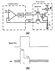
CA 02510855 2005-07-06
FIG. 1 (a) shows the implementation of the new driving method and associated
waveforms.
The column driver consists of a differential amplifier with a high voltage
gain in series with a
lead compensator (H(s)). H(s) is generally in the form of
H(s)- 1+sz_
1+szP
where z,,< r for non-zero values of zZ and zp. zp can be equal to zero. The
exact values of z and zp
are designed based on the circuit parameters such as parasitic capacitance of
the data and
feedback, gain and unity-gain bandwidth of the differential amplifier, and the
mobility of the thin
film transistors of the pixel circuit. The lead compensation can enhance the
settling time of the
current in the AMOLED pixel circuit, in particular the settling time at larger
programming
currents associated with higher greyscales.
FIG. 1 (b) shows the driving signals of the column driver. For small
programming currents
associated with lower greyscales, the data signal (Vin) during the programming
time consist of a
primary accelerating pulse between t, and tz, and the final data value between
t2 and t3 . The
amplitude of the accelerating pulse (Vp"~se) is higher than the data value
(Vda~) for small currents.
For large currents, (Vp"ise) can be equal or even smaller than (Vda~). The
exact value of (Vp"ise) is
defined based on the circuit parameters, and the value of (V~a~).
FIG. 2 shows a general method for compact implementation of the column driver
by combining
the lead compensator with the differential amplifier. It consists of a traps-
conductance differential
amplifier with a gain of Gm, a voltage gain stage with a gain of A, and a
compensating MOS
transistor M1 and capacitor C~. Ml can be a NMOS or PMOS transistor or a
transmission gate.
The value of z is determined by capacitor C~ and the resistance of transistor
M1. For fine tuning
of the value of t~, the gate of M1 is connected to a controlling voltage (V~).
FIG. 3 shows the simulation results of the proposed driving method. The
waveforms are the
programming currents of an AMOLED pixel circuit with feedback, when driven by
the new
driving method and when driven by a simple differential amplifier without
accelerating pulse and
lead compensator. As can be seen, the new driving method is able to
considerably improve the
programming speed.
3