Language selection

Search

Patent 2510942 Summary

Third-party information liability

Some of the information on this Web page has been provided by external sources. The Government of Canada is not responsible for the accuracy, reliability or currency of the information supplied by external sources. Users wishing to rely upon this information should consult directly with the source of the information. Content provided by external sources is not subject to official languages, privacy and accessibility requirements.

Claims and Abstract availability

Any discrepancies in the text and image of the Claims and Abstract are due to differing posting times. Text of the Claims and Abstract are posted:

  • At the time the application is open to public inspection;
  • At the time of issue of the patent (grant).
(12) Patent Application: (11) CA 2510942
(54) English Title: CARGO DECK FOR TRUCK BOX
(54) French Title: RAMPE DE CHARGEMENT POUR CAISSE DE CAMION
Status: Dead
Bibliographic Data
(51) International Patent Classification (IPC):
  • B65G 69/28 (2006.01)
(72) Inventors :
  • THYGESEN, MARK (Canada)
(73) Owners :
  • THYGESEN, MARK (Canada)
(71) Applicants :
  • MARATHON MARINE MANUFACTURING (1996) LTD. (Canada)
(74) Agent: THOMPSON, DOUGLAS B.
(74) Associate agent:
(45) Issued:
(22) Filed Date: 2005-06-27
(41) Open to Public Inspection: 2006-12-27
Availability of licence: N/A
(25) Language of filing: English

Patent Cooperation Treaty (PCT): No

(30) Application Priority Data: None

Abstracts

English Abstract


A rail assembly for a telescoping ramp including a slider rail that is taller
than it is
wide, having opposed ends, opposed faces, and opposed edges. First ramp
attachment means
protrude outwardly from a first of the opposed faces. There is a hollow
channel rail with a
first side wall that consists of spaced co-planar wall segments that form a
gap making the
channel rail generally C-shaped in cross-section, the channel rail has an
interior surface that
defines an interior channel adapted to accommodate the slider rail with at
least one of the
opposed edges of the slider rail serving as a bearing surface which slides
along the interior
surface and the first ramp attachment means protruding through the gap between
the wall
segments. A second ramp attachment means protrudes outwardly from one of the
wall
segments.


Claims

Note: Claims are shown in the official language in which they were submitted.


6~
What is Claimed is:
1. A rail assembly for a telescoping ramp, comprising:
a slider rail that is taller than it is wide, having opposed ends, opposed
faces, and
opposed edges;
first ramp attachment means protruding outwardly from a first of the opposed
faces;
a hollow channel rail with a first side wall consisting of spaced co-planar
wall
segments forming a gap making the channel rail generally C-shaped in cross-
section, the
channel rail having an interior surface that defines an interior channel
adapted to
accommodate the slider rail with at least one of the opposed edges of the
slider rail serving as
a bearing surface which slides along the interior surface and the first ramp
attachment means
protruding through the gap between the wall segments;
second ramp attachment means protruding outwardly from one of the wall
segments.
2. The rail assembly as defined in Claim 1, wherein the channel rail is
generally parallel-
piped.
3. The rail assembly as defined in Claim 1, wherein the slider rail is an
aluminum extrusion.
4. The rail assembly as defined in Claim 1, wherein the channel rail is an
aluminum
extrusion.
5. The rail assembly as defined in Claim 1, wherein the first ramp attachment
means are a pair
of parallel spaced flanges.
6. The rail assembly as defined in Claim 5, wherein the parallel spaced
flanges extend for
substantially an entire length of the slider rail between the opposed ends.
7. The rail assembly as defined in Claim 1, wherein the second ramp attachment
means are a
pair of parallel spaced flanges.


7
8. The rail assembly as defined in Claim 7, wherein the parallel spaced
flanges extend for
substantially an entire length of the channel rail.
9. The rail assembly as defined in Claim 1, wherein gutters are positioned
along the edges of
interior surface of the channel rail.
10. The rail assembly as defined in Claim 1, wherein structural ribs protrude
from a second of
the opposed faces of the slider rail, the structural ribs extending between
the opposed ends.
11. The rail assembly as defined in Claim 1, wherein structural ribs protrude
from a second
side wall of the charnel rail.
12. The rail assembly as defined in Claim 1, wherein an attachment hook is
mounted to a
second side wall at a first end of the channel rail.
13. The rail assembly as defined in Claim 12, wherein the attachment hook is
mounted by
means of a hook mounting receiver.
14. The rail assembly as defined in Claim 13, wherein the hook mounting
receiver is
symmetrical and adapted to facilitate the attachment hook from being secured
in more than
one orientation.
15. The rail assembly as defined in Claim 12, wherein the attachment hook has
a safety catch
which pivots freely in a first direction to permit insertion of an anchor bar
into the attachment
hook and resists pivotal movement in a second direction, thereby preventing
accidental
release of the anchor bar.
16. The rail assembly as defined in Claim 1, wherein two slider rails are
provided in parallel
spaced relation with a first opposed edge of a first ramp section secured to
the first ramp
attachment means of a first of the two slider rails and a second opposed edge
of the first ramp
section secured the first ramp attachment means of a second of the two slider
rails; and
two channel rails are provided in parallel spaced relation with a first
opposed edge of


8

a second ramp section secured to the second ramp attachment means of a first
of the two
channel rails and a second opposed edge of the second ramp section secured to
the second
ramp attachment means of a second of the two channel rails.
17. A rail assembly for a telescoping ramp, comprising:
a slider rail that is taller than it is wide, having opposed ends, opposed
faces, and
opposed edges;
first ramp attachment means protruding outwardly from a first of the opposed
faces,
the first ramp attachment means being a pair of parallel spaced flanges that
extend for
substantially an entire length of the slider rail between the opposed ends;
a generally parallel-piped hollow channel rail with a first side wall
consisting of
spaced co-planar wall segments forming a gap making the channel rail generally
C-shaped in
cross-section, the channel rail having an interior surface that defines an
interior channel
adapted to accommodate the slider rail with at least one of the opposed edges
of the slider rail
serving as a bearing surface which slides along the interior surface and the
first ramp
attachment means protruding through the gap between the wall segments;
second ramp attachment means protruding outwardly from one of the wall
segments,
the second ramp attachment means being a pair of parallel spaced flanges that
extend for
substantially an entire length of the channel rail.
18. The rail assembly as defined in Claim 17, wherein the slider rail and the
channel rail are
aluminum extrusions.
19. The rail assembly as defined in Claim 17, wherein structural ribs protrude
from a second
of the opposed faces of the slider rail, the structural ribs extending between
the opposed ends.
20. The rail assembly as defined in Claim 17, wherein structural ribs protrude
from a second
side wall of the channel rail.
21. A telescoping ramp, comprising:
two slider rails, each slider rail being is taller than it is wide, with
opposed ends,


9
opposed faces, and opposed edges;
first ramp attachment means protruding outwardly from a first of the opposed
faces;
the two slider rails being positioned in parallel spaced relation with a first
opposed
edge of a first ramp section secured to the first ramp attachment means of a
first of the two
slider rails and a second opposed edge of the first ramp section secured the
first ramp
attachment means of a second of the two slider rails;
two hollow channel rails, each channel rail having a first side wall
consisting of
spaced co-planar wall segments forming a gap making the channel rail generally
C-shaped in
cross-section, each channel rail having an interior surface that defines an
interior channel
adapted to accommodate one of the slider rails with at least one of the
opposed edges of the
slider rail serving as a bearing surface which slides along the interior
surface and the first
ramp attachment means protruding through the gap between the wall segments;
second ramp attachment means protruding outwardly from one of the wall
segments;
and
the two channel rails being positioned in parallel spaced relation with a
first opposed
edge of a second ramp section secured to the second ramp attachment means of a
first of the
two channel rails and a second opposed edge of the second ramp section secured
to the
second ramp attachment means of a second of the two channel rails.
22. The telescoping ramp as defined in Claim 21, wherein the first ramp
attachment means are
a pair of parallel spaced flanges and the ramp is made from a plurality of
cross-member
members that extend between the two slide rails in parallel spaced relation
and which are
secured in a channel defined by the parallel spaced flanges.
23. The telescoping ramp as defined in Claim 21, wherein the second ramp
attachment means
are a pair of parallel spaced flanges and the ramp is made from a plurality of
cross-member
members that extend between the two channel rails in parallel spaced relation
and which are
secured in a channel defined by the parallel spaced flanges.
24. The rail assembly as defined in Claim 1, wherein gutters are positioned
along the edges of
interior surface of the channel rail.


10

25. The telescoping ramp as defined in Claim 21, wherein the two slider rails
and the two
channel rails are aluminum extrusions.

26. The telescoping ramp as defined in Claim 21, wherein an attachment hook is
mounted to
one of a side wall at a first end of each of the two channel rails or a side
wall at one of the
opposed ends of each of the two slider rails.

27. The telescoping ramp as defined in Claim 26, wherein the attachment hook
is mounted by
means of a hook mounting receiver.

28. The telescoping ramp as defined in Claim 27, wherein the hook mounting
receiver is
symmetrical and adapted to facilitate the attachment hook from being secured
in more than
one orientation.

29. The telescoping ramp as defined in Claim 26, wherein the attachment hook
has a safety
catch which pivots freely in a first direction to permit insertion of an
anchor bar into the
attachment hook and resists pivotal movement in a second direction, thereby
preventing
accidental release of the anchor bar.


Description

Note: Descriptions are shown in the official language in which they were submitted.


CA 02510942 2005-06-27
1
TITLE OF THE INVENTION:
Rail Assembly For A Telescoping Ramp
FIELD OF THE INVENTION
The present invention relates to rail system for a telescoping ramp and a
telescoping
ramp that is constructed using such a rail assembly. The telescoping ramp is
of the type used
to load and unload a cargo area of a truck.
BACKGROUND OF THE INVENTION
Telescoping ramps are known in the art. There are a number of existing
configurations of telescoping ramp, including the following U.S. Patents:
5,536,058 (Otis
1996); 5,813,071 (Breslin et al 1998); 6,345,950 (Gerwitz 2002); and 6,484,344
(Cooper
2002).
SUMMARY OF THE INVENTION
According to the present invention there is provided a rail assembly for a
telescoping
ramp, which includes a slider rail and a hollow channel rail. The slider rail
is taller than it is
wide, with opposed ends, opposed faces, and opposed edges. First ramp
attachment means
protrude outwardly from a first of the opposed faces. The hollow channel rail
has a first side
2 0 wall consisting of spaced co-planar wall segments forming a gap making the
channel rail
generally C-shaped in cross-section. The channel rail has an interior surface
that defines an
interior channel adapted to accommodate the slider rail with at least one of
the opposed edges
of the slider rail serving as a bearing surface which slides along the
interior surface and the
first ramp attachment means protruding through the gap between the wall
segments. Second
2 5 ramp attachment means protrude outwardly from one of the wall segments.
BRIEF DESCRIPTION OF THE DRAWINGS
These and other features of the invention will become more apparent from the
3 0 following description in which reference is made to the appended drawings,
the drawings are
for the purpose of illustration only and are not intended to in any way limit
the scope of the
invention to the particular embodiment or embodiments shown, wherein:


CA 02510942 2005-06-27
2
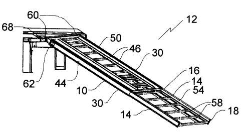
FIG. 1 is a perspective view of a telescoping ramp constructed in accordance
with the
teachings of the present invention, in an extended position.
FIG. 2 is a perspective view of the telescoping ramp illustrated in FIG. 1, in
a
retracted position.
FIG. 3 is an end elevation view, in section, of the telescoping ramp
illustrated in FIG.
1.
FIG. 4 is detailed perspective view of the telescoping ramp illustrated in
FIG. 1., with
attachment hooks in a first orientation.
FIG. 5 is detailed perspective view of the telescoping ramp illustrated in
FIG. 1., with
attachment hooks in a second orientation.
FIG. 6 is a detailed perspective view of the telescoping ramp illustrated in
FIG. 1
attached to an anchor bar.
FIG. 7 is a perspective view of the telescoping ramp illustrated in FIG. 1
adapted to
load snowmobiles.
FIG. 8 is a perspective view of the telescoping ramp illustrated in FIG. 1
adapted to
load ATVs.
DETAILED DESCRIPTION OF THE PREFERRED EMBODIMENT
The preferred embodiment, a rail assembly for a telescoping ramp generally
identified
2 0 by reference numeral 10, will now be described with reference to FIG.1
through 8.
Rail Structure:
Referring now to FIG. 1, rail assembly I 0 for a telescoping ramp 12 includes
a slider
rail 14 and a channel rail 30. Slider rail 14 is taller than it is wide, has
opposed ends 16 and
2 5 18, and, referring to FIG. 3, opposed faces 20 and 22, and opposed edges
24 and 26. A first
ramp attachment means, such as a pair of parallel spaced flanges 28, extend
for substantially
the entire length of slider rail 14 between opposed ends 16 and 18 and
protrude outwardly
from opposed face 20. Channel rail 30 is generally parallel-piped and hollow
with a first side
wall 32 consisting of spaced co-planar wall segments 34 that form a gap to
make channel rail
3 0 30 generally C-shaped in cross-section. Channel rail 30 has an interior
surface 36 that defines
an interior channel 38 adapted to accommodate slider rail 14 with either
opposed edges 24 or
26 of slider rail 14 serving as a bearing surface 25 that slides along
interior surface 36, and


CA 02510942 2005-06-27
3
flanges 28 protruding through the gap between wall segments 34. Alternatively,
opposed
edges 24 and 26 may incorporate wheels or other means to act as a bearing
surface. Both
slider rail 14 and channel rail 30 are preferably aluminium extrusions. It is
preferred that
"gutters" 37 be positioned along the edges of interior surface 36 of channel
rail 30, to provide
a space for debris to go. A second ramp attachment means, such as parallel
spaced flanges
40 that extend for substantially the entire length of channel rail 30 protrude
outwardly from
one of the wall segments 34. For improved strength and performance, structural
ribs 42 may
be included that protrude from face 22 of slider rail 14 and extend between
opposed ends 16
and 18. There may also be structural ribs 44 protruding from a second side
wall 45 of
channel rail 30. Structural ribs 42 and 44 may be used for a variety of
functions. They may
form a channel for attachment hook 60, act as a splice reinforcement, a roller
channel, a
spacer, or be used to stiffen slider rail 14.
Telescoping ramp structure:
Referring now to FIG. 3, telescoping ramp 12 includes two slider rails 14 and
two
channel rails 30 as described above. Slider rails 14 include first ramp
attachment means, such
as parallel spaced flanges 28. Referring to FIG. 1, a plurality of cross-
member members 46
extend between two slider rails 14 in parallel spaced relation to form a first
ramp section 50.
It will be appreciated that cross-member members 46 can serve as support for
some form of
2 0 covering substrate or could be replaced by a solid sheet. It is preferred
to use cross-member
members 46 and cover portions with a covering substrate, as it is less
expensive. Referring
again to FIG. 3, cross-member members 46 are secured in a channel 48 defined
by parallel
spaced flanges 28. Slider rails 14 are positioned in parallel spaced relation
with a first
opposed edge 49 of the first ramp section 50 secured to parallel spaced
flanges 28 of one of
2 5 the two slider rails 14 and a second opposed edge 51 of first ramp section
50 secured to
parallel spaced flanges 28 of the other slider rail 14.
Referring to FIG.1, a plurality of cross-member members 58 extend between two
channel rails 14 in parallel spaced relation to form a second ramp section 50.
Referring to
3 0 FIG. 3, the two channel rails 30 are positioned in parallel spaced
relation with a first opposed
edge 52 of the second ramp section 54 secured to in a channel 55 defined by
parallel spaced
flanges 40 (second ramp attachment means) of one of the two channel rails 30
and a second

CA 02510942 2005-06-27
4
opposed edge 56 of second ramp section 54 secured in a channel 55 defined by
parallel
spaced flanges 40 of the other channel rail 30.
As will hereinafter be further described, ramp 12 is able to be extended and
retracted.
The extended position is shown in FIG.1, and the retracted position is shown
in FIG. 2.
Referring to FIG. 3, one of opposed edges 24 or 26 of slider rail 14 serve as
bearing surface
25 that slides along interior surface 36 of channel rail 30.
Referring now to FIG. 4, an attachment hook 60 is mounted to a second side
wall 45
at a first end 62 of each of the two channel rails 30 by means of a hook
mounting receiver 64.
Hook mounting receiver 64 is symmetrical and adapted to facilitate the
attachment hook 60
from being secured in more than one orientation. The other orientation is
shown in FIG. 5.
Refernng to FIG. 6, attachment hook 60 also has a safety catch 66 which pivots
freely in a
first direction to permit insertion of an anchor bar 68 into attachment hook
60 and resists
pivotal movement in a second direction, thereby preventing accidental release
of anchor bar
68. Referring to FIGS. 7 and 8, attachment hook 60 may be made reversible to
permit ramp
12 to be adapted to load different types of vehicles, for example. FIG. 7
shows ramp 12
adapted to load snowmobiles, and FIG. 8 shows ramp 12 adapted to load ATVs.
2 0 Operation:
The use and operation of rail assembly 10 for a telescoping ramp 12 will now
be
discussed with reference to FIGS. 1 through 8. Referring to FIG. 3, slider
rail 14 is
positioned in channel rail 30 as discussed above, with cross-member members 46
and 58
installed between parallel spaced flanges 28 and 40, respectively, to form
first ramp section
2 5 50 and second ramp section 54. Referring to FIG. 6, ramp 12 is installed
by attaching
attachment hook 66 on anchor bar 68. As anchor bar 68 is inserted into
attachment hooks 60,
safety catch 66 pivots in a first direction to permit insertion of anchor bar
68. Once anchor
bar 68 is fully inserted, safety catch 66 returns to its original position and
resists further
movement in the second direction to prevent accidental release of anchor bar
68. Referring to
3 0 FIGS. 1 and 2, ramp can then be extended or kept in the retracted
position, depending on the
loading or unloading requirements. Refernng to FIG. 7 and 8, ramp 12 may be
removed and
reversed if a different type of vehicle is being loaded Referring to FIG. 4
and 5, this is done

4 ~
CA 02510942 2005-06-27
by removing attachment hooks 60 from hook mounting receivers 64 and replacing
them in the
other orientation. To remove ramp 12 from anchor bar 68, safety catch 66 is
lifted until an
opening is provided in attachment hook 60 that is wide enough to allow anchor
bar 68 to pass.
5 In this patent document, the word "comprising" is used in its non-limiting
sense to
mean that items following the word are included, but items not specifically
mentioned are not
excluded. A reference to an element by the indefinite article "a" does not
exclude the
possibility that more than one of the element is present, unless the context
clearly requires that
there be one and only one of the elements.
It will be apparent to one skilled in the art that modifications may be made
to the
illustrated embodiment without departing from the spirit and scope of the
invention as
hereinafter defined in the Claims.

Representative Drawing
A single figure which represents the drawing illustrating the invention.
Administrative Status

For a clearer understanding of the status of the application/patent presented on this page, the site Disclaimer , as well as the definitions for Patent , Administrative Status , Maintenance Fee  and Payment History  should be consulted.

Administrative Status

Title Date
Forecasted Issue Date Unavailable
(22) Filed 2005-06-27
(41) Open to Public Inspection 2006-12-27
Dead Application 2007-09-28

Abandonment History

Abandonment Date Reason Reinstatement Date
2006-09-28 FAILURE TO RESPOND TO OFFICE LETTER
2007-06-27 FAILURE TO PAY APPLICATION MAINTENANCE FEE

Payment History

Fee Type Anniversary Year Due Date Amount Paid Paid Date
Application Fee $200.00 2005-06-27
Owners on Record

Note: Records showing the ownership history in alphabetical order.

Current Owners on Record
THYGESEN, MARK
Past Owners on Record
None
Past Owners that do not appear in the "Owners on Record" listing will appear in other documentation within the application.
Documents

To view selected files, please enter reCAPTCHA code :


To view images, click a link in the Document Description column. To download the documents, select one or more checkboxes in the first column and then click the "Download Selected in PDF format (Zip Archive)" or the "Download Selected as Single PDF" button.

List of published and non-published patent-specific documents on the CPD .

If you have any difficulty accessing content, you can call the Client Service Centre at 1-866-997-1936 or send them an e-mail at CIPO Client Service Centre.


Document
Description 
Date
(yyyy-mm-dd) 
Number of pages   Size of Image (KB) 
Abstract 2005-06-27 1 19
Description 2005-06-27 5 206
Claims 2005-06-27 5 175
Drawings 2005-06-27 4 76
Representative Drawing 2006-11-29 1 13
Cover Page 2006-12-13 1 44
Correspondence 2007-08-22 1 93
Correspondence 2005-08-10 1 26
Correspondence 2005-08-10 1 33
Assignment 2005-06-27 2 70
Correspondence 2006-06-28 1 47
Correspondence 2006-11-09 1 53
Correspondence 2007-02-28 1 39