Note: Descriptions are shown in the official language in which they were submitted.
CA 02510974 2005-06-28
GEAR GRINDING MACHINE
Background of the Invention
1. Field of the Invention
This invention relates to a gear grinding machine
arranged to perform grinding (gear machining) using a
threaded grinding wheel, and equipped with a dressing device
for dressing the threaded grinding wheel . The gear grinding
machine can easily correct an error (dimensional error),
if any, in a ground gear.
2. Description of the Related Art
A gear grinding machine, in which a gear-shaped
workpiece after heat treatment is ground by "a threaded
grinding wheel", a gear grinding tool, to finish a gear,
has so far been known. The threaded grinding wheel is an
annular grinding wheel having threads (rack teeth) formed
spirally on its outer peripheral surface. Grinding is
performed by numerically controlling the positions in an
orthogonalcoordinatesystem(positionson the X-axis,Y-axis
and Z-axis) of the threaded grinding wheel, the rotational
speed of the threaded grinding wheel, and the rotational
speed of a table on which the work (gear) has been installed.
As grinding proceeds, the threaded grinding wheel
wears,anditssharpnessdecreases. Thus, after the threaded
grinding wheel has ground many gears continuously, the
worn-out threaded grinding wheel needs to be dressed by a
1
4
CA 02510974 2005-06-28
dressing device to regenerate a sharp cutting edge.
Some gear grinding machines are equipped with dressing
devices. Among the dressing devices is a rotary dressing
device provided with a rotationally driven disk-shaped
dressing tool. With this rotary dressing device, the
disk-shaped dressing tool is kept rotationally driven, and
brought into contact with the flank of the thread of the
threaded grinding wheel being rotated, thereby carrying out
dressing.
If the shape of the ground gear is not the target shape,
but has a shape error, actions of the gear grinding machine
need to be modified.
In this case, the "gear shape error" includes a "tooth
profile error" and a "helix form deviation".
To correct the "tooth profile error" of the gear to
be ground, namely, to modify its tooth profile (tooth profile
pressure angle), the wheel pressure angle of the threaded
grinding wheel has to be modified. Modification of the wheel
pressure angle of the threaded grinding wheel is made by
dressing the threaded grinding wheel by the dressing device.
To correct the "helix form deviation" of the gear to
be ground, on the other hand, it is common practice-to modify
synchronous motions made when the gear (work) placed on a
rotating table is ground by the threaded grinding wheel.
That is, the helix form deviation can be corrected by modifying
synchronization between motions of the threaded grinding
wheel moving in a Z-axis direction (i. e. , vertical direction) ,
2
4 ,
CA 02510974 2005-06-28
and rotary motions of the table, on which the work is placed,
during grinding.
Concretely, the moving motion in the Z-axis direction
of the threaded grinding wheel is slowed, or the rotary motion
of the table is quickened, whereby the helix angle of the
gear is increased. On the other hand, the moving motion in
the Z-axis direction of the threaded grinding wheel is
increased, or the rotary motion of the table is slowed, whereby
the helix angle of the gear is decreased. Thus, the
synchronization between the moving motion in the Z-axis
direction of the threaded grinding wheel and the rotary motion
of the table is adjusted, whereby the helix angle of the
gear can be arbitrarily set and modified. By so adjusting
the synchronization, the helix angle of the gear to be ground
can be modified to correct the helical form deviation.
One of methods for modifying the wheel pressure angle
is to turn (turn about a vertical axis (Z-axis)) the
disk-shaped dressing tool in contact with the thread of the
threaded grinding wheel, although details will be described
later on.
Among gear grinding machines, therefore, are those
of the type having a mechanism for turning the rotary dressing
device. With the gear grinding machine having such a turning
mechanism, an operator manually turns the rotary dressing
device (dressing tool) about the Z-axis by use of a block
gauge, which is a tool for turning, to modify the wheel
pressure angle.
3
1.
CA 02510974 2005-06-28
When the wheel pressure angle of the threaded grinding
wheel is modified to correct the tooth profile error, the
tooth profile can be modified. Such correction of the tooth
profile error does not affect the form of the tooth trace.
If the synchronization between the moving motion in
the Z-axis direction of the threaded grinding wheel and the
rotary motion of the table is modified to correct the helix
form deviation, on the other hand, the form of the tooth
trace can be modified. Such correction of the helix form
deviation inevitably results in the modification of the tooth
profile. Since the correction of the helix form deviation
leads to modification of the tooth profile, as described
above, an unintended tooth profile may be obtained.
The present invention has been accomplished in light
oftheabove-described problemswiththeearliertechnologies.
It is an obj ect of the present invention to provide a gear
grinding machine which can appropriately correct a tooth
profile error and a helix form deviation in anticipation
of a change in a tooth profile according to correction of
the helix form deviation, if there is an error or deviation
of the tooth profile and the tooth trace form.
Summary of the Invention
An aspect of the present invention is a gear grinding
machine comprising:
a table on which a work is installed, and which rotates
4
CA 02510974 2005-06-28
about a vertical axis;
a moving mechanism rotatably mounted with a threaded
grinding wheel having threads spirally formed on an outer
peripheral surface thereof, and arranged to move the threaded
grinding wheel along an X-direction being a direction in
which the threaded grinding wheel advances or retreats with
respect to the table, a Z-direction being a vertical direction,
and a Y-direction being a direction perpendicular to the
X-direction and the Z-direction, and to turn the threaded
grinding wheel in a Y-Z plane;
an NC device for numerically controlling the movement
of the moving mechanism in order to control the position
of the threaded grinding wheel mounted on the moving mechanism,
and for numerically controlling the rotary motion of the
table; and
a rotary dressing device having a disk-shaped dressing
tool, and arranged such that when the rotary dressing device
is set at a position where the table has been placed, the
dressing tool contacts the flank of the threads of the threaded
grinding wheel, while being rotationally driven, to perform
dressing, and
wherein the NC device has
an input function unit for inputting a tooth profile
error and a helix form deviation representing a dimensional
error of a gear machined by the gear grinding machine,
a tooth profile deformationamount computingfunction
unit for finding a tooth profile deformation amount generated
i, ,
CA 02510974 2005-06-28
in the gear when adj usting synchroni zation between a moving
motion in a Z-axis direction of the threaded grinding wheel
and the rotary motion of the table so as to correct the helix
form deviation,
an addition function unit for adding the inputted tooth
profile error and the tooth profile deformation amount to
find a total tooth profile error,
a pressure angle error computing function unit for
finding a pressure angle error corresponding to the total
tooth profile error,
a helix angle modification amount computingfunction
unit for finding a helix angle modification amount necessary
for correcting the inputted helix form deviation, and
an NC control function unit for adjusting the
synchronization between the moving motion in the Z-axis
direction of the threaded grinding wheel and the rotary motion
of the table so that a helix angle formed in the work is
changed by the helix angle modification amount.
Another aspect of the present invention is a gear
grinding machine comprising:
a table on which a work is installed, and which rotates
about a vertical axis;
a moving mechanism rotatably mounted with a threaded
grinding wheel having threads spirally formed on an outer
peripheral surface thereof, and arranged to move the threaded
grinding wheel along an X-direction being a direction in
which the threaded grinding wheel advances or retreats with
6
,,. ,
,..
CA 02510974 2005-06-28
respect to the table, a Z-direction being a vertical direction,
and a Y-direction being a direction perpendicular to the
X-direction and the Z-direction, and to turn the threaded
grinding wheel in a Y-Z plane;
an NC device for numerically controlling the movement
of the moving mechanism in order to control the position
of the threaded grinding wheel mounted on the moving mechanism,
and for numerically controlling the rotary motion of the
table; and
a rotary dressing device having a disk-shaped dressing
tool, and arranged such that when the rotary dressing device
is set at a position where the table has been placed, the
dressing tool contacts the flank of the threads of the threaded
grinding wheel, while being rotationally driven, to perform
dressing, and
wherein the NC device has
a.n input function unit for inputting a tooth profile
error and a helix form deviation representing a dimensional
error of a gear machined by the gear grinding machine,
a tooth profile deformation amount computingfunction
unit for finding a tooth profile deformation amount generated
in the gear when adjusting synchronization between a moving
motion in a Z-axis direction of the threaded grinding wheel
and the rotary motion of the table so as to correct the helix
form deviation,
an addition function unit for adding the inputted tooth
profile error and the tooth profile deformation amount to
7
CA 02510974 2005-06-28
find a total tooth profile error,
a pressure angle error computing function unit for
finding a pressure angle error corresponding to the total
tooth profile error,
a pressure angle modification amount computing
function unit for finding a pressure angle modification
amount necessary for correcting the pressure angle error,
a grinding wheelposition correction amount computing
function unit for finding a grinding wheel position
correction amount corresponding to the pressure angle
modification amount,
a helix angle modification amount computing function
unit for finding a helix angle modification amount necessary
for correcting the inputted helix form deviation, and
an NC control function unit for adjusting the
synchronization between the moving motion in the Z-axis
direction of the threaded grinding wheel and the rotary motion
of the table so that a helix angle formed in the work is
changed by the helix angle modification amount, and for
modifying the position of the threaded grinding wheel by
the grinding wheel position correction amount in correcting
the tooth profile error by adjusting a position in the
X-direction, a position in the Z-direction, and a turning
position in the Y-Z plane of the threaded grinding wheel,
while keeping the dressing tool in contact with the flank
of the threads of the threaded grinding wheel.
Still another aspect of the present invention is a
8
r ", .
i.
CA 02510974 2005-06-28
gear grinding machine comprising:
a table on which a work is installed, and which rotates
about a vertical axis;
a moving mechanism rotatably mounted with a threaded
grinding wheel having threads spirally formed on an outer
peripheral surface thereof, and arranged to move the threaded
grinding wheel along an X-direction being a direction in
which the threaded grinding wheel advances or retreats with
respect to the table, a Z-direction being a vertical direction,
and a Y-direction being a direction perpendicular to the
X-direction and the Z-direction, and to turn the threaded
grinding wheel in a Y-Z plane;
an NC device for numerically controlling the movement
of the moving mechanism in order to control the position
of the threaded grinding wheel mounted on the moving mechanism,
and for numerically controlling the rotary motion of the
table; and
a rotary dressing device having a disk-shaped dressing
tool, and arranged such that when the rotary dressing device
is set at a position where the table has been placed, the
dressing tool contacts the flank of the threads of the threaded
grinding wheel, while being rotationally driven, to perform
dressing, and
wherein the NC device has
an input function unit for inputting a tooth profile
error and a helix form deviation representing a dimensional
error of a gear machined by the gear grinding machine,
9
E
CA 02510974 2005-06-28
atooth profile deformationamount computingfunction
unit for finding a tooth profile deformation amount generated
in the gear when adjusting synchronization between a moving
motion in a Z-axis direction of the threaded grinding wheel
and a rotary motion of the table so as to correct the helix
form deviation,
an addition function unit for adding the inputted tooth
profile error and the tooth profile deformation amount to
find a total tooth profile error,
a pressure angle error computing function unit for
finding a pressure angle error corresponding to the total
tooth profile error,
a pressure angle modification amount computing
function unit for finding a pressure angle modification
amount necessary for correcting the pressure angle error,
a lead correction amount computing function unit for
finding a lead correction amount corresponding to the
pressure angle modification amount,
a helix angle modification amount computing function
unit for finding a helix angle modification amount necessary
for correcting the inputted helix form deviation, and
an NC control function unit for adjusting the
synchronization between the moving motion in the Z-axis
direction of the threaded grinding wheel and the rotary motion
of the table so that a helix angle formed in the work is
changed by the helix angle modification amount, and for
modifying a moving distance in the Y-direction of the threaded
4
CA 02510974 2005-06-28
grinding wheel per rotation of the threaded grinding wheel
by the lead correction amount to adjust the moving distance
in the Y-direction of the threaded grinding wheel per rotation
of the threaded grinding wheel.
Brief Description of the Drawings
The present invention will become more fully
understood from the detailed description given hereinbelow
and the accompanying drawings which are given by way of
illustration only, and thus are not limitative of the present
invention, and wherein:
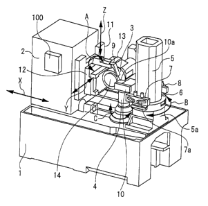
FIG. 1 is a perspective view showing a gear grinding
machine;
FIGS. 2(a) to 2(c) are plan views showing the
surroundings of a counter column in the gear grinding machine;
FIG. 3 is a side view showing the surroundings of the
counter column in the gear grinding machine;
FIG. 4 is a perspective view showing the state of
grinding a gear;
FIG. 5 is a schematic view showing the state of
dressing;
FIGS. 6 (a) to 6 (c) are explanation drawings showing
the state of dressing; and
FIG. 7 is a block diagram showing the computing
functions of an embodiment of the present invention.
11
E
CA 02510974 2005-06-28
Detailed Description of the Invention
First of all, the features and general actions of a
gear grinding machine, to which the present invention has
been applied, will be described with reference to FIGS. 1
to 5.
FIG. 1 is a perspective view of a gear grinding machine
according to an embodiment of the present invention having
a threaded grinding wheel (worm grinding wheel) 3 mounted
thereon. This view illustrates a state in which the threaded
grinding wheel 3 is dressed (ground for regeneration) by
a pair of dressing tools l0a and lOb provided in a rotary
dressing device 10. The threaded grinding wheel 3 of an
annular shape has rack teeth (spiral threads) on the outer
peripheral surface thereof, and these rack teeth engage a
work (gear to be ground) W to carry out gear grinding.
FIGS. 2(a) to 2(c) are explanation drawings of the
surroundings of a counter column 5, as viewed from above,
which is a tailstock for supporting an end of the work. FIGS.
2 (a) and 2 (b) show actions for carrying the work W into and
out of a site on a table 4. FIG. 2(c) shows the state of
dressing.
FIG. 3 is a side view of the counter column (tailstock)
5.
FIG. 4 is a perspective view showing a state in which
the threaded grinding wheel 3 and the work W are in engagement
for gear grinding.
12
.,
CA 02510974 2005-06-28
FIG. 5 is a schematic view showing the state of
dressing.
In FIG. 1, the numeral 1 is a bed, 2 is a column, 3
is the threaded grinding wheel for grinding the work, 4 is
the table on which the work is placed and held, 5 is the
counter column (tailstock) erected on the bed 1, 6 is a turning
ring (annular member) revolvably provided on the outer
periphery of a lower part of the counter column 5, 7 and
8 axe grippers for carrying-in and carrying-out of the work,
and 10 is the rotary dressing device for dressing the threaded
grinding wheel 3.
The table 4 is provided at a position facing the column
2 (i. e. , a work machining position) , and the column 2 moves
forward and backward on the bed 1 toward and away from a
first axis C1 (table 4) shown in FIG. 2 (a) (namely, the column
2 slides in an X-direction). The column 2 has a grinding
spindle 14 as a wheel spindle for mounting the threaded
grinding wheel 3. The table 4 rotates in directions of arrows
C about the first axis C1 shown in FIG . 2 (a) (i . a . , rotates
about a vertical axis).
The counter column 5 has the function of pressing the
work, placed on the table 4, from above, and has a tailstock
instrument (not shown) which ascends and descends in an
up-and-down direction above the face of the table 4 to press
the work from above.
As shown in FIG. 2(a), the turning ring (annular
member) 6, which is turned about a second axis 0 in directions
13
..,, .
CA 02510974 2005-06-28
of arrows B (FIG. 1) by a drive means (not shown) , is provided
on the outer periphery of the counter column 5. The pair
of grippers 7 and 8, which are holders of the work, and the
rotary dressing device 10 are provided on the turning ring
6.
The pair of grippers 7 and 8 are provided symmetrically
with respect to the second axis 0 for carrying the work W
into and out of the site on the table 4. The grippers 7 and
8 have such a mechanism that a pair of opening and closing
forks 7a, 7a or 8a, 8a grip the work W from both sides of
it, and hold it.
The turning ring 6 is desirably provided on the outer
periphery of the lower part of the counter column 5 in
consideration of a height which makes it easy for the grippers
7, 8 to carry the work W into and out of the site on the
table 4.
The rotary dressing device 10 is provided between the
grippers 7 and 8, and is preferably provided at a central
( 90-degree ) position between the grippers 7 and 8, with the
second axis O as the center.
The rotary dressing device 10 is furnished with the
pair of disk-shaped dressing tools l0a and lOb which are
rotationally driven about a dresser axis lOc.
The column 2 has, on a side surface (front surface)
thereof facing the table 4, a vertical slide 11 slidable
parallel to the first axis C1 (i.e., in a Z-direction), a
turning head 12 capable of axially turning on the front surface
14
". . , , ,
CA 02510974 2005-06-28
of the vertical slide 11 in directions of arrows A (i.e.,
capable of turning about an X-axis and capable of turning
in a Y-Z plane), and a grinding slider 13 sliding on the
front surface of the turning head 12 in a direction
perpendicular to the first axis C1 (i.e., in a Y-direction) .
The above axial turns in the A-direction mean motions which
tilt the whole of the grinding spindle 14. The grinding
spindle 14 rotates about a grinding wheel axis 3a, thereby
enabling the work W to be ground by the threaded grinding
wheel 3.
The bed 1, the column 2, the vertical slide 11, the
turning head 12, the grinding slider 13, and the grinding
spindle 14 constitute a moving mechanism, and the respective
portions of this moving mechanism have their moving positions
numerically controlled by an NC device 100.
The turning head 12 is provided with a coolant nozzle
9, through which a grinding fluid is discharged from above
a site of grinding during grinding of the work W and the
threaded grinding wheel 3 to ensure smoothness of grinding,
exclusion of grinding swarf, and cooling.
The movements in the directions of X, Y, Z, A and C
of the above-mentioned moving mechanism, the rotational
driving of the threaded grinding wheel 3 by the grinding
spindle 14, and the rotational driving of the table 4 are
numerically controlled by the NC device 100, whereby the
threaded grinding wheel 3 grinds the work W on the table
4.
.~ . ..., a
,,
CA 02510974 2005-06-28
The carry-in, carry-out, and machining actions for
the work W will be described based on FIGS. 2 (a) , 2 (b) and
2 (c) .
FIG. 2 (a) is a view showing a state in which the work
W is carried into the site on the table 4 on the side of
the gripper 7, and a work W1 to be ground next is gripped
on the side of the gripper 8.
The gripper 7 is lowered by a predetermined distance
by a moving means (not shown) to install the work W at a
work mounting instrument (work arbor) on the table 4 . After
gripping by the gripper 7 is released, the work W is fixed
to and supported on the work arbor by a clamping device (not
shown). Then, the movements in the directions of X, Y, Z,
A and C of the moving mechanism, the rotational driving of
the threaded grinding wheel 3, and the rotational driving
of the table 4 are numerically controlled, whereby the
threaded grinding wheel 3 grinds the work W to produce a
gear W2. FIG. 4 shows the state of the threaded grinding
wheel 3 and the work W relative to each other during grinding.
At this time, synchronization between the moving
motion in the Z-axis direction of the threaded grinding wheel
3 being rotationally driven and the rotary motion of the
table 4, on which the work (gear) W is installed, is adjusted,
whereby the helix angle (form of helix trace) formed in the
work (gear) W can be adjusted.
Then, the fixing and support of the gear W2 on the
work arbor are released, and the gear W2 is gripped by the
16
,. . .
CA 02510974 2005-06-28
gripper 7. The gripper 7 is raised by a predetermined
distance by the moving means to separate the gear W2 from
the work arbor. Then, the turning ring 6 is rotated clockwise
(in a direction of an arrow D) through 180 degrees to attain
the state shown in FIG. 2(b). At this time, the gripper 8
grips the work W1 to be ground next, and the gripper 8 carries
the work W1 into the site on the table 4, and the gripper
7 carries the completed gear W2 out.
By repeating the actions shown in FIGS. 2 (a) and 2 (b)
alternately,severaltensofgearsare produced continuously.
Then, the turning ring 6 is turned from the state of FIG.
2(b) clockwise through 90 degrees in the direction of an
arrow F to attain the states shown in FIG. 2(c) and FIG.
3. That is, the rotary dressing device 10 is brought
face-to-face with the threaded grinding wheel 3. The
dressing tools 10a, 10b are rotationally driven about the
dresser axis lOc. Further, the movements in the directions
of X, Y, Z, A and C and the rotational driving of the threaded
grinding wheel 3 are numerically controlled in the same manner
as for machining of the work W, whereby the threaded grinding
wheel 3 is ground by the dressing device 10 for regeneration.
The timing of dressing of the threaded grinding wheel
3 by the rotary dressing device 10 is set beforehand in the
NC device 100 of the gear grinding machine before execution
of grinding, with the number of the works W to be ground
continuously by the threaded grinding wheel 3 being set at
a predetermined number. By so doing, the actions shown in
17
,.,.,.. .
i ,,
CA 02510974 2005-06-28
FIGS. 2(a) and 2(b) are repeated alternately so that the
threaded grinding wheel 3 machines the predetermined number
of the works W continuously. After the predetermined number
of the works W are continuously machined, the turning ring
6 is turned and brought to the state of FIG. 2 (c) . As a result,
the rotary dressing device 10 faces the threaded grinding
wheel 3, making it possible for the rotary dressing device
to dress the threaded grinding wheel 3.
Dressing is performed by rotationally driving the
dressing tools l0a and lOb about the dresser axis lOc, and
numerically controlling the movements in the directions of
X, Y, Z, A and C of the threaded grinding wheel 3 and the
rotational driving of the threaded grinding wheel 3.
In this manner, the disk-shaped dressing tools l0a
and lOb being rotationally driven are brought into contact
with the flanks of the threads of the threaded grinding wheel
3 being rotated, whereby dressing of the threaded grinding
wheel 3 can be carried out.
FIG. 5 schematically shows a state in which the
threaded grinding wheel 3 is dressed by the dressing tools
10a, lOb.
In FIG. 5, assume that the dressing tool l0a can turn
(turn about the Z-axis) about a position P1, and the dressing
tool lOb can turn (turn about the Z-axis) about a position
P2. In this case, the wheel pressure angle of the threaded
grinding wheel 3 can be modified by turning the dressing
tools 10a, lOb about the Z-axis.
18
.., , .
,., ....,, .
CA 02510974 2005-06-28
With the aforementioned gear grinding machine having
a block gauge, the wheel pressure angle can be modified by
such a technique. By so modifying the wheel pressure angle,
the gear pressure angle (tooth profile) of the work (gear)
W can be modified.
The method of correcting the tooth profile error by
modifying the wheel pressure angle in the above-described
manner is called "the first tooth profile error correction
method".
Alternatively, the wheel pressure angle of the
threaded grinding wheel 3 can be changed in the manner
described below, without turning the dressing tools 10a,
lOb about the Z-axis.
That is, with the position of the rotary dressing
device 10 (i.e., dressing tools 10a, lOb) being fixed, and
the dressing tools 10a, lOb being kept in contact with the
flanks of the threads of the threaded grinding wheel 3, the
threaded grinding wheel 3 is located at a predetermined
position in an orthogonal coordinate system (in a direction
along the X-axis and the Z-axis) , and the threaded grinding
wheel 3 is turned through a predetermined angle in the
direction of the arrow A. By these measures, the wheel
pressure angle of the threaded grinding wheel 3 to be dressed
by the dressing tools 10a, 10b can be changed.
In other words, "the positions of the dressing tools
10a, lOb are fixed, while the orthogonal coordinate position
and the turning angle in the direction of the arrow A of
19
.,. ,
.. ..E. ... ,.
CA 02510974 2005-06-28
the threaded grinding wheel 3 are changed" . This procedure
attains a state equivalent to the state in which "the position
of the threaded grinding wheel 3 is fixed, while the dressing
tools 10a, lOb are turned about the Z-axis", in order to
change the wheel pressure angle.
The method of correcting the tooth profile error by
modifying the wheel pressure angle in the above-described
manner is called "the second tooth profile error correction
method".
Concrete methods for this purpose will be described
with reference to FIGS. 6(a) to 6(c).
In performing ordinary dressing, a line connecting
the center O1 of the threaded grinding wheel 3 (the central
point of the grinding wheel axis 3a) and the center 02 of
the dressing tools 10a, lOb (the central point of the dresser
axis lOc) is rendered horizontal, as shown in FIG. 6(a).
At this time, a center distance, which is the distance between
the centers O1 and O2, is D.
To change the wheel pressure angle of the threaded
grinding wheel 3, the positions of the dressing tools 10a,
lOb are fixed at the same positions as in FIG. 6(a), and
the center distance as the distance between the centers O1
and OZ is kept to be D (namely, the dressing tools 10a, lOb
are kept in contact with the flanks of the threads of the
threaded grinding wheel 3). Under these conditions, the
position in the X-direction and the position in the
Z-direction of the threaded grinding wheel 3 are changed,
.. ~ .,. . ,
h ".t.., ., . ,
CA 02510974 2005-06-28
and the position in the A-direction of the threaded grinding
wheel 3 (its turning position about the X-axis, namely, its
turning position in the Y-Z plane) is also changed, for example,
as shown in FIG. 6(b). In the example of FIG. 6(b), the
threaded grinding wheel 3 and the dressing tools 10a, lOb
are in contact at the lower-half portions of the threads
of the threaded grinding wheel 3.
Thus, for example, the wheel pressure angle at the
right flank RF (see FIG. 5) of the threaded grinding wheel
3 dressed by the dressing tool l0a is large, and the wheel
pressure angle at the left flankhF (see FIG. 5) of the threaded
grinding wheel 3 dressed by the dressing tool lOb is small,
although this is dependent partly on the direction of
inclination of the threads formed in the threaded grinding
wheel 3.
At this time, the increase (numerical value) in the
wheel pressure angle at the right flank RF is equal to the
decrease (numerical value) in the wheel pressure angle at
the left flank ZF.
How much the threaded grinding wheel 3 should be moved
along its positions in the directions of X, Z and A in order
to change the wheel pressure angle by a predetermined angle
can be found analytically.
It goes without saying that the threaded grinding wheel
3 is moved along its positions in the directions of X, Z
and A by moving the column 2, the vertical slide 11, and
the turning head 12 while controlling their positions in
21
. ..r . .. . ..., ,
.,k . . ...,..,..,. ,
CA 02510974 2005-06-28
the NC mode by the NC device 100.
In carrying out dressing, the positions of the threaded
grinding wheel 3 in the directions of X, Z and A are maintained
in the state shown in FIG. 6(b), and contact adjustment is
made until the dressing tools 10a, lOb contact the flanks
of the threads of the threaded grinding wheel 3 (namely,
the threaded grinding wheel 3 is moved in the Y-direction) .
Then, the threaded grinding wheel 3 is continuously lead-fed
in the Y-direction in accordance with the lead of the threads
formed in the threaded grinding wheel 3.
To change the wheel pressure angle of the threaded
grinding wheel 3 in a direction opposite to the direction
shown in FIG. 6 (b) , the positions of the dressing tools 10a,
lOb are fixed at the same positions as in FIG. 6(a), and
the center distance as the distance between the centers O1
and OZ is kept to be D. Under these conditions, the position
in the X-direction and the position in the Z-direction of
the threaded grinding wheel 3 are changed, and the position
in the A-direction of the threaded grinding wheel 3 (its
turning position about the X-axis, namely, its turning
position in the Y-Z plane) is also changed, for example,
as shown in FIG. 6(c). In the example of FIG. 6(c), the
threaded grinding wheel 3 and the dressing tools 10a, lOb
are in contact at the upper-half portions of the threads
of the threaded grinding wheel 3.
Thus, for example, the wheel pressure angle at the
right flank RF (see FIG. 5) of the threaded grinding wheel
22
r . . > , . ." ,
,~ , . . .
CA 02510974 2005-06-28
3 dressed by the dressing tool l0a is small, and the wheel
pressure angle at the left flank LF (see FIG. 5) of the threaded
grinding wheel 3 dressed by the dressing tool lOb is large,
although this is dependent partly on the direction of
inclination of the threads formed in the threaded grinding
wheel 3.
At this time, the decrease (numerical value) in the
wheel pressure angle at the right flank RF is equal to the
increase (numerical value) in the wheel pressure angle at
the left flank LF.
How much the threaded grinding wheel 3 should be moved
along its positions in the directions of X, Z and A in order
to change the wheel pressure angle by a predetermined angle
can be found analytically.
It goes without saying that the threaded grinding wheel
3 is moved along its positions in the directions of X, Z
and A by moving the column 2, the vertical slide 11, and
the turning head 12 while controlling their positions in
the NC mode by the NC device 100.
In carrying out dressing, the positions of the threaded
grinding wheel 3 in the directions of X, Z and A are maintained
in the state shown in FIG. 6(c), and contact adjustment is
made until the dressing tools 10a, lOb contact the flanks
of the threads of the threaded grinding wheel 3 (namely,
the threaded grinding wheel 3 is moved in the Y-direction) .
Then, the threaded grinding wheel 3 is continuously lead-fed
in the Y-direction in accordance with the lead of the threads
23
. . ,~ . . . . . ...,:.-. , . "
CA 02510974 2005-06-28
formed in the threaded grinding wheel 3.
In this manner, the wheel pressure angle at the right
flank and that at the left flank of the threaded grinding
wheel 3 can be increased for one of the right and left flanks,
and decreased for the other flank. Furthermore, the increase
and the decrease (numerical values) in the wheel pressure
angle can be equated with each other.
In FIGS. 6(a) to 6(c), if the wheel pressure angle
is increased (decreased) at the right flank RF, the wheel
pressure angle is decreased (increased) at the left flank
hF. According to the following "third tooth profile error
correction method", the wheel pressure angles at the right
and left flanks are both increased, or both decreased.
During ordinary dressing, the distance over which the
threaded grinding wheel 3 is continuously moved in the
Y-direction(moving distancein the Y-direction perrotation)
is equated with the lead of the threads formed in the threaded
grinding wheel 3. According to the third tooth profile error
correction method, by contrast, the distance over which the
threaded grinding wheel 3 is continuously moved in the
Y-direction(moving distancein the Y-direction per rotation)
during dressing is rendered slightly longer or shorter than
the lead of the threads formed in the threaded grinding wheel
3.
As has been well known thus far, if the moving distance
of the threaded grinding wheel 3 in the Y-direction per
rotation is longer than the lead of the threads of the threaded
29
," " , ,
CA 02510974 2005-06-28
grinding wheel 3, the wheel pressure angles at the right
and left flanks RF and LF of the threaded grinding wheel
3 dressed by the dressing tools 10a, lOb are both decreased
by the same angle (numerical value) , for example, although
this is also dependent on the direction of the inclination
of the threads formed in the threaded grinding wheel 3. If
the moving distance of the threaded grinding wheel 3 in the
Y-direction per rotation is shorter than the lead of the
threads of the threaded grinding wheel 3, on the other hand,
the wheel pressure angles at the right and left flanks RF
and LF of the threaded grinding wheel 3 dressed by the dressing
tools 10a, lOb are both increased by the same angle (numerical
value) , for example, although this is also dependent on the
direction of the inclination of the threads formed in the
threaded grinding wheel 3.
Furthermore, the second tooth profile error
correction method and the third tooth profile error
correction method can be combined.
That is,
(1) The moving distance of the threaded grinding
wheel 3 in the Y-direction per rotation is adjusted; and
(2) With the positions of the dressing tools 10a,
lOb being fixed at the same positions as in FIG. 6(a), and
the center distance as the distance between the centers O1
and 02 being kept to be D, the position in the X-direction,
and the position in the Z-direction of the threaded grinding
wheel 3 are changed.
..,.__... :, .....>.. ~. _.
. .,.,~ , , . ,
CA 02510974 2005-06-28
By taking these measures, the wheel pressure angles
at the right and left flanks RF and LF can be increased or
decreased to arbitrary angles.
Embodiment:
In the Embodiment of the present invention, if the
measurement of the dimensions of a gear, which has been
produced by grinding by means of the gear grinding machine
shown in FIG. 1, shows a gear shape error, the actions of
the gear grinding machine are modified by modification and
computing function units of the NC device 100 in the manner
described below.
FIG. 7 shows modification and computing function units
extracted from the computing function units of the NC device
100. Needless to say, the NC device 100 exercises ordinary
numericalcontrol,namely,numericalcontrolofthe movements
in the X, Y, Z, A and C directions of the moving mechanism,
the rotational driving of the threaded grinding wheel 3 by
the grinding spindle 14, and the rotational driving of the
table 4. However, such ordinary NC function units are not
shown.
According to the present embodiment, the dimensions
of a gear produced by grinding are measured by a measuring
device or the like. If the measurements show a gear shape
error (tooth profile error, helix form deviation), an
operator inputs the gear shape error into the modification
and computing function units of the NC device 100 via an
26
....,r. . ~ ... , .. "..,....
.,,...~. , ..
CA 02510974 2005-06-28
input unit 101 of the NC device 100.
Concretely, a tooth profile error (data) x ~m of the
left tooth flank, a tooth profile error (data) y ~tm of the
right tooth flank, and a helix form deviation (data) z ~m
are inputted.
A tooth profile deformation amount computing unit 102
finds a tooth profile deformation amount w ~.m, which has
been generated when synchronization (synchronization
between the moving motion in the Z-axis direction of the
threaded grinding wheel 3 and the rotary motion of the table
4 having the work installed thereon) is modified to eliminate
the helix form deviation z Vim, by a preset operation
expression.
An addition unit 103 adds the above tooth profile
deformation amount w um to each of the inputted tooth profile
errors x ~,m and y ~.m to obtain total tooth profile errors
x' ~tm and y' Vim. That is, x' - x+w and y' - y+w.
A pressure angle error computing unit 104 finds
pressure angle errors DaL deg and LIaR deg corresponding to
the total tooth profile errors x' ~,m and y' Vim.
The pressure angle errors Daz deg and llaR deg are
displayed in a display unit 105. The operator sees the
pressure angle errors ~aL deg and DaR deg displayed in the
display unit 105 and, in an attempt to eliminate these pressure
angle errors Daz deg and DaR deg, turns the dressing tools
10a, lOb about the z-axis to change the wheel pressure angle
of the threaded grinding wheel 3 in accordance with the "first
27
.......r.. " .,.>,, , ..,
., , , ,
CA 02510974 2005-06-28
tooth profile error correction method". As a result, the
pressure angle errors Daz deg and DaR deg can be removed.
A pressure angle modification amount computing unit
106 finds a pressure angle modification amount Dal deg which
is used when employing the "third tooth profile error
correction method", a method in which the pressure angle
is modified by modifying the moving distance in the
Y-direction (lead) of the threaded grinding wheel 3 per
rotation of the threaded grinding wheel 3. At this time,
0a 1 = ( ~aL+QaR ) / 2 .
A lead correction amount computing unit 107 finds a
lead correction amount LW mm corresponding to the pressure
angle modification amount Dal deg.
An NC control unit 108 exercises lead-feed numerical
control so as to correct the moving distance in the Y-direction
(lead) of the threaded grinding wheel 3, during dressing
of the threaded grinding wheel 3, by the lead correction
amount LW mm, when making a tooth profile error correction
by the "third tooth profile correction method".
A pressure angle modification amount computing unit
109 finds a pressure angle modification amount ~a2~, deg at
the right tooth f lank and a pressure angle modification amount
~a2Rdeg at the left tooth flank, which are used when employing
the "second tooth profile error correction method", a method
in which the pressure angle is modified by modifying the
position in the X-axis direction and the position in the
Z-axis direction of the threaded grinding wheel 3. At this
28
"F ~ ~.,..~ , ~ ..
CA 02510974 2005-06-28
time,
Aa2z = Daz - Dal deg
~a2R = DaR - dal deg
On this occasion, Da2z = -Da2R
A grinding wheelposition correctionamount computing
unit 110 finds grinding wheel position correction amounts
~X mm and OZ mm corresponding to the pressure angle
modification amounts Aa2L deg and Aa2R deg.
The NC control unit 108 numerically controls the
position of the threaded grinding wheel 3 so as to correct
the position in the X-direction and the position in the
Z-direction of the threaded grinding wheel 3, during dressing
of the threaded grinding wheel 3, by ~X mm and ~Z mm while
dressing the threaded grinding wheel 3 by the dressing device
10, when making a tooth profile error correction by the "second
tooth profile correction method".
Upon receipt of the helix form deviation z um, a helix
angle modification amount computing unit 111 finds a helix
angle modification amount ~(3 necessary for correcting the
helix form deviation z um.
When the NC control unit 108 is synchronizing the
moving motion in the Z-axis direction of the threaded grinding
wheel 3 and the rotary motion of the table 4 by numerical
control so that a helix angle of (3 is obtained, the NC control
unit 108 modifies the synchronization between the moving
motion in the Z-axis direction of the threaded grinding wheel
3 and the rotary motion of the table 4 by numerical control
29
.. , ,r , . . ..
..,. ..... . . .
CA 02510974 2005-06-28
so that the helix angle will become (3-D/3.
In the above-described manner, the helix form
deviation z ~m can be corrected and removed, and the tooth
profile errors x ~.m and y ~,m can be corrected and removed.
If correction of the helix form deviation (i.e.,
modification of the helix angle) is made when employing the
"third tooth profile error correction method", a method in
which the pressure angle is modified by modifying the moving
distance in the Y-direction (lead) of the threaded grinding
wheel 3 per rotation of the threaded grinding wheel 3, the
tooth profile error changes (the pressure angle changes)
inevitably as a result of the correction of the helix form
deviation. An example of the tooth profile error change will
be indicated by mathematical expressions.
Normal helix angle (31
Normal pressure angle and
Normal transverse pressure angle asl
Normal pitch circle diameter dol
Normal base circle diameter dgl
Normal lead Lol
Helix angle modification amount D(3
Lead after correction
Lolh = ~~dol/tan((31+0(~)
Helix angle after correction
[31h = sin-1 (n-Mnl ~ zl/Lolh)
where Mnl is a module, and zl is the number
of teeth
~.._..~.._.~__.__.._..~. .. .~..,~....~_.,......
. .. .a . , .... .' . . . .
CA 02510974 2005-06-28
Transverse pressure angle after correction
aslh = tan-1 (tan (anl) /cos ((31h) )
Pitch circle diameter after correction
dolh = Mnl~ zl/cos ((31h)
Base circle diameter after correction
dglh = dolh~cos(aslh)
Find a pressure angle which is equal to the pressure
angle (anlh) at the normal base circle (dgl ) , without changing
the lead (Lolh)
Transverse pressure angle after correction
aslh = cos-1 (dgl ~ cos ((31h) /Mnl ~ zl )
Pressure angle after correction
anlh = tan-1 (tan (aslh) ~ cos ((31h) )
Pressure angle correction amount
~anl = anlh - and
Pressure angle change amount after lead correction
-flan 1
Thus, a change in the pressure angle after change of
the lead, accordingly, the helix angle is -~anl.
The tooth profile deformation amount computing unit
102 finds a tooth profile error, which is necessarily caused
when the helix form deviation z ~tm is corrected, based on
the above correction amount -Danl.
As described above, the present invention can be
applied to the gear grinding machine which allows the threaded
grinding wheel to perform grinding, and which has the rotary
dressing device for dressing the threaded grinding wheel.
31
-...r.. ~.._....~...~. ..... , .. ..w.. ..~~ ..... .
.~.. _ "..~.... ,,
CA 02510974 2005-06-28
The present invention can be utilized for modifying the
actions of the gear grinding machine so as to resolve a gear
shape error, if any, in a gear produced by grinding.
According to the present invention, moreover, if there
is a helix form deviation and a tooth profile error in a
gear produced by grinding, the actions of the gear grinding
machine are not modified simply so as to correct the helix
form deviation and the tooth profile error, but the actions
of the gear grinding machine are modified so as to correct
the tooth profile error in consideration of a tooth profile
deformation amount which is necessarily generated by
correcting the helix form deviation. Thus, the helix form
deviation and the tooth profile error can be properly
corrected.
The invention thus described, it will be obvious that
the same may be varied in many ways. Such variations are
not to be regarded as a departure from the spirit and scope
of the invention, and all such modifications as would be
obvious to one skilled in the art are intended to be included
within the scope of the following claims.
32
_....._._. ,. ..._ ... ~. ......... ._... . _ _