Note: Descriptions are shown in the official language in which they were submitted.
CA 02511277 2015-07-22
Application No. 2,511,277
Attorney Docket No. 22150-7
ILLUMINATION SYSTEM FOR DENTISTRY APPLICATIONS
CA 02511277 2015-07-22
Application No. 2,511,277
Attorney Docket No. 22150-7
ILLUMINATION SYSTEM FOR DENTISTRY APPLICATIONS
Cross-Reference to Related Applications
[001] This application claims the benefit of U.S. provisional
patent applications Serial No. 60/585,224, filed July 2, 2004,
entitled "Dental Light Devices With Phase Change Heat Sink";
60/641,462, filed January 4, 2005, entitled "Boom Hinge For A
Dental Lamp"; 60/647,725, filed January 26, 2005, entitled
"Automatic Control for a Dental Whitening Lamp"; 60/647,723,
filed January 26, 2005, entitled "Boom Hinge For A Dental Lamp";
60/658,517, filed March 3, 2005, entitled "Apparatus and Method
For Radiation Spectrum Shifting in Dentistry Application";
60/641,469, filed January 4, 2005, entitled "Lamp For Dentistry
Applications"; 60/647,580, filed January 26, 2005, entitled
"Light Guide For Dental Whitening Lamp"; 60/641,461, filed
January 4, 2005, entitled "Support Structure For A Dental Lamp";
60/641,468, filed January 4, 2005, entitled "Light Guide For A
Dental Whitening Lamp"; 60/647,612, filed January 26, 2005,
entitled "Light Path Apparatus For A Dental Lamp"; 60/647,593,
filed January 26, 2005, entitled "Support Structure For A Dental
Lamp"; 60/604,577, filed August 25, 2004, entitled "Lip
Retractors"; 60/594,297, filed March 25, 2005, entitled "Curing
Light Having A Detachable Tip"; 60/631,267, filed November 26,
2004, entitled "Curing Light Having A Reflector"; 60/594,327,
filed on March 30, 2005, entitled, "Curing Light"; and
60/664,696, filed March 22, 2005, entitled "Curing Light Having
A Detachable Tip".
[004 The present application may relate to the
following U.S. design applications No.: 29/220,642, filed
January 4, 2005, entitled "Lamp For Dentistry Applications";
29/220,680, filed January 4, 2005, entitled "Light Guide For
2
CA 02511277 2015-07-22
Application No. 2,511,277
Attorney Docket No. 22150-7
...
Dentistry Applications"; 29/220,679, filed January 4, 2005,
entitled "Power Pack For Dentistry Applications"; 29/220,712,
filed January 4, 2005, entitled "Support Structure For A Lamp
For Dentistry".
[003]
Field of the Invention
[004] This invention relates to illumination systems used in
dentistry. Specifically, this invention relates to illumination
systems used in dental curing, dental whitening or imaging.
Background of the Invention
[005] A tooth is comprised of an inner dentin layer and an outer
hard enamel that is coated with a protective layer called the
acquired pellicle. The enamel layer is composed of
3
CA 02511277 2005-06-30
Customer No. / Attorney Docket No.: 000053096 / D2000-0004-P002
hydroxyapatite crystals that create a somewhat porous surface.
The pellicle or the enamel can become stained or discolored. It
is believed that the porous nature of the enamel layer is what
allows staining agents and discoloring substances to permeate
the enamel and discolor the tooth.
[006] Tooth discoloration has a number of causes. For example,
the teeth may become stained by coffee or tea drinking, or by
the use of tobacco products, or by drinking water with a high
mineral content.
[007] One solution to the staining problem is through tooth
bleaching. Some dentifrices, like toothpastes, gels, and
powders, contain active oxygen or hydrogen peroxide liberating
bleaching agents including peroxides, percarbonates and
perborates of the alkali and alkaline earth metals or complex
compounds containing hydrogen peroxide.
[008] Dental bleaching can be done either in a dental office or
at home.
Bleaching in a dental office generally employs
compositions activatable with the aid of light sources having
the appropriate wavelength outputs in order to speed up the
process.
Additionally, the bleaching compositions used in a
dental office typically contain a higher percentage
concentration of bleaching agents than the bleaching
compositions found in home applications.
[009] In addition to staining, tooth decay, resulting in cavities
or other damages can also result. In the field of tooth
restoration and repair, dental cavities are often filled and/or
sealed with compounds that are photosensitive, either to visible
and/or ultraviolet light. These compounds, commonly known as
light-curable compounds, are placed within dental cavity
4
CA 02511277 2005-06-30
Customer No. / Attorney Docket No.: 000053096 / D2000-0004-P002
preparations or onto dental surfaces and are cured when exposed
to light from a dental curing light device.
100101 Unlike dental curing and imaging processes, which are
generally relatively fast processes, dental bleaching takes a
much longer time, sometimes amounting to more than an hour per
office visit. On the other hand, dental restoration is often an
unwelcome experience. Therefore, it is advantageous that a
person undergoing the processes, either dental restoration or
bleaching, be as comfortable as possible.
[0011] The process is generally performed in a dentist's chair.
Typically a dentist's chair has a wide range of adjustability
such that a patient may be placed in a wide range of positions
from a nearly full reclining position to a nearly upright
position. In order to effectively accomplish the whitening or
restoration process, a light source needs to be aligned with the
mouth. The wide range of dentist's chair positions can make this
alignment difficult.
[0012] Further considerations in the process of dental procedures
include the ability to maintain cleanliness of the light source,
and particularly of any part that comes into contact with the
patient.
Further, the process of whitening is, for example,
optimized, that is, the light source is on as long as necessary
to whiten the teeth to the desired degree. Still further, it is
desirable that the light source be as efficient as possible. An
efficient lamp tends to be cooler and therefore safer than an
inefficient lamp. Also, an efficient lamp requires less energy
to run than an inefficient lamp.
[0013] It remains desirable to have an efficient and comfortable
apparatus and method for dental whitening, curing and imaging.
CA 02511277 2005-06-30
Customer No. / Attorney Docket No.: 000053096 / D2000-0004-P002
Summary of the Invention
[0013] The present invention is directed to a system, an apparatus
and method for dental whitening, curing or imaging, that is
efficient, comfortable for the patient and further includes
improved safety, maintenance and operating features.
[0014]The present invention is also directed to an alignment
system to facilitate faster patient set up and optimal results.
[0015] The alignment system includes an apparatus for positioning
a dental illumination device relative to a subject, including a
lamp system, a reference device, and a spacer for engaging both
the reference device and the lamp system for positioning the
lamp system at a predetermined distance from the reference
device.
[0016]In one embodiment, the reference device and the spacer
include formations that removably inter-engage as the reference
device and spacer become apposed.
[0017]In another embodiment, the spacer and the lamp system
include formations that removably inter-engage as the spacer and
the lamp system become apposed.
[0018] In a further embodiment, the spacer and at least one of its
formations are integrally formed with the lamp system.
[0019]The inter-engaging formations serve to stabilize the spacer
axially and against twisting.
[0020] Furthermore, the present invention includes a support
mechanism that is unobtrusive, easily adjustable, and able to
6
CA 02511277 2005-06-30
Customer No. / Attorney Docket No.: 000053096 / D2000-0004-P002
provide positioning in multiple degrees of freedom so as to be
adaptable to the requirements of patients of various sizes.
[0021] The lamp system and a support system include formations
that removably inter-engage as the lamp system and the support
system become apposed.
[0022] According to a first embodiment of the invention, a dental
whitening or curing light source includes at least one light
source such as, for example, an ultraviolet light source for
activating a dental whitening or curing composition. The light
source may include a lamp, an arc lamp such as a halogen light
source, semiconductor light emitting devices, light-emitting
chips such as an LED, a solid state LED, an LED array, a
fluorescent bulb, and so on. In the case of dental imaging, the
light source may include the above in addition to a laser, an x-
ray or even an infrared source. According to a second embodiment
of the invention, multiple light sources arranged in a geometric
arrangement may be used. In one aspect, an illumination frame
may be disposed inside the lamp head housing. In another aspect,
the illumination frame may be in place of the lamp head housing
as a self-contained structure. In a further aspect, the
illumination frame may be in addition to the lamp head housing.
The light sources may be collectively powered or individually
powered. If individually powered, each of the individual light
sources may be turned on or off separately, as desired.
[0023] In one embodiment, the illumination frame may be adapted to
be coupled to the spacer and the spacer is adapted to be coupled
to the reference device. In another aspect, the spacer may be an
integral part of the lamp system, adapted to be coupled to the
reference device. According to a further aspect, an illumination
frame includes at least one light source set in the illumination
7
CA 02511277 2005-06-30
Customer No. / Attorney Docket No.: 000053096 / D2000-0004-P002
frame to illuminate at least one tooth in the mouth of a dental
patient.
[0024] In one embodiment, the illumination frame may, for example,
conform to the jaw of a patient and have a first end and a
second end.
The first and second ends include a first and
second formations, such as slots, configured to mate with a
first and a second formation, such as a wing-like member,
respectively, of a reference device such as a lip retracting
device.
The arcuate shape of the illumination system may be
configured to follow the curvature of the human head so that the
light sources are substantially equidistant from the various
teeth in a dental patient. The light source may be capable of
whitening, curing or imaging.
[0025]
In another embodiment of the invention, the illumination
frame is rectangular with a first slotted structure on one side
of the rectangle and a second slotted structure on the opposite
side of the rectangle configured to mate with wing-like members
on a lip retracting device worn by a dental patient.
In one embodiment of the invention, a path is provided from a
light source to a target such as a whitening composition disposed
on a tooth surface, a filling compound residing either on the
surface or in the cavity of a tooth, or a tooth for imaging. In
one aspect, the light path includes a light source capabale of
imaging, whitening or curing. In another aspect, the light path
includes a light source and at least one reflector integral to
the light source. According to a further aspect, the invention
includes a second reflector having an axial cavity with a first
aperture at an end proximate the light source and a second
aperture distal to the light source.
The second reflector
includes a reflective internal surface adapted to direct light
from the light source towards the second aperture by reflection.
In one embodiment, an optical lens is disposed within the second
8
CA 02511277 2005-06-30
Customer No. / Attorney Docket No.: 000053096 / D2000-0004-P002
reflector.
According to another embodiment, the optical lens
includes at least one curved surface and is adapted to direct
light from the light source towards the second aperture by
refraction. According to yet another embodiment, an optical
filter is disposed coincident with the second aperture.
The
optical filter serves to impede the passage of various
wavelengths of light while allowing the passage of other
wavelengths. In a further embodiment, the optical filter serves
to prevent, for example, most light having a wavelength
characterized as in the infrared range from passing through the
second aperture to the target, if desired. In contrast, light in
the ultraviolet and/or visible ranges are allowed to pass, if
desired.
[0026] According to a further embodiment of the invention, a light
path apparatus including a reflector, a lens, a filter, and a
diffusion element is disclosed. The diffusing element may be
used to spatially homogenize the spectrum output of a light
source. According to one aspect of the invention, a diffusing
element may be employed to produce scattering of light at an
input surface thereof to generate a randomized and spatially
equalized output light pattern. According to another aspect of
the invention, the diffusing element includes a textured surface
adapted to provide scattering of received light. In a further
aspect, the diffusing element includes a frosted surface, for
example, a frosted glass portion or a frosted glass produced by
etching. In another example, a frosted plastic surface element
is employed. As in the case of a frosted glass element, the
plastic element may be frosted by etching, or by a mechanical
crazing process. In other examples, the diffusing element may
include a textured surface having a plurality of striations
thereon, a plurality of ridges, a corrugated pattern, a
plurality of microscopic hemispherical bumps, a plurality of
microscopic conical projections, or any other surface feature
9
CA 02511277 2005-06-30
Customer No. / Attorney Docket No.: 000053096 / D2000-0004-P002
adapted to produce the desired scattering of light. In still
other examples of the invention, the diffusing element includes
a transparent or translucent material having a plurality of
suitably sized particles suspended in a layer, or otherwise
throughout a body of the diffusing element.
The suspended
particles may be spherical, or may exhibit any other appropriate
physical geometry.
[0027] According to one embodiment of the invention, the diffusing
element is disposed between the light source and a lens. The
lens serves to refract light received from the light source,
directly or indirectly, by reflection from various surfaces, and
to refract light towards the target area.
In one embodiment,
the lens includes a substantially rectangular periphery.
In
another embodiment, a peripheral edge of the lens is
substantially circular, elliptical, or otherwise configured
according to the particular requirements of any given embodiment
of the invention. In a further embodiment, the lens includes a
curved output surface region and a substantially flat input
region. In yet another embodiment, the lens includes a curved
input region and a substantially flat output region. In still
another embodiment of the invention, the lens includes a curved
output region, and an input surface that includes both curved
and flat regions, where the curved region minimizes refractive
characteristics of the lens within a particular area while
providing desirable refraction in other portions of the
illumination pattern produced by the light source, or light
source and diffusing element.
[00281 According to another embodiment of the invention, a light
path apparatus including a reflector, a lens, a filter, an
integrator and diffusing element is disclosed. In one aspect,
according to various embodiments of the invention, a light path
apparatus includes a housing having a reflector surface and an
CA 02511277 2005-06-30
Customer No. / Attorney Docket No.: 000053096 / D2000-0004-P002
integrator surface.
The reflector surface redirects divergent
rays of light towards an input of a lens, or lens system. The
integrator surface redirects divergent rays of light received
from an output surface of the lens or lens system towards an
output aperture of the light path apparatus.
[0029] According to one embodiment of the invention, the light
path apparatus housing is formed of metal, such as, for example,
formed sheet metal. In another embodiment of the invention, the
light path apparatus housing is formed of a polymer material,
including, for example, a reinforced polymer composite material.
[0030] In still another embodiment of the invention, the light
path apparatus includes an optical filter. The optical filter
serves to absorb and/or reflect light of various wavelengths,
and in particular wavelengths of desirable ranges in terms of
the applications of the dental lamp system. For example, where
an output of the dental lamp is desired to be principally within
the ultraviolet spectrum, the optical filter will absorb and
otherwise reject at least some light of visible and/or infrared
wavelengths.
P0311 In one embodiment of the invention, the optical filter is
disposed distal to the light source, such that the diffuser
element and lens are disposed between the light source device
and the optical filter. In one embodiment of the invention, the
optical filter is disposed immediately adjacent to, or within,
an aperture at an output and of the light path apparatus.
Consequently, light suitable for activating a dental whitening
compound, or for any other dentistry process, is available
outside of the second aperture, if present.
Meanwhile, for
example, infrared light, which would otherwise unduly elevate
the temperature of the target area, unless useful in a dental
11
CA 02511277 2005-06-30
Customer No. / Attorney Docket No.: 000053096 / D2000-0004-P002
process, is excluded from the target area, or is reduced to
acceptable levels.
[002]According to at least one embodiment of the invention, an
elastomeric mounting is provided to mechanically couple the
filter in position in the light path.
Furthermore, one
embodiment of the invention includes another elastomeric
mounting disposed to mechanically couple the optical lens to a
position in the light path. The elastomeric mountings serve, in
various aspects of the invention, to protect the lens and filter
respectively against mechanical shock and to compensate for
differences in coefficient of thermal expansion present between
various materials employed in the device of the invention.
[0033] According to a further embodiment of the invention, a light
source and reflector assembly are disposed within a lamp
housing. The lamp housing includes fixturing features adapted
to hold the light source and a reflector assembly within an
axial cavity of the lamp housing. The lamp housing includes a
rear aperture proximate to the light source and a front aperture
proximate to the second aperture of the reflector.
[0034] According to at least one embodiment of the invention, at
least one wavelength transformer may be included. The wavelength
transformer may act to transform shorter wavelengths outside of
the useful range for whitening imaging or curing, into longer
wavelengths in the useful range, thus minimizing energy waste.
In one aspect, the wavelength transformer may be disposed within
the lamp housing. In another aspect, the wavelength transformer
may be part of the light source. In a third aspect, the
wavelength transformer may be constructed into a modular device
adapted to be installed or removed from the lamp housing of the
whitening, imaging or curing light source, whenever desired.
12
CA 02511277 2005-06-30
Customer No. / Attorney Docket No.: 000053096 / D2000-0004-P002
[0035] In another embodiment of the invention, a grill is disposed
coincident with the rear aperture.
In one aspect, the grill
includes perforations for heat dissipation or to allow the
passage of a cooling medium, such as air.
[0036] In one embodiment of the invention, the lamp housing also
includes a cooling system for maintaining the light source, and
other components of the lamp head at a desirable temperature, a
high operating temperature of the light source notwithstanding.
In one embodiment, the cooling system includes a fan.
In
another embodiment, the cooling system includes a heat sink. In
still another embodiment, the cooling system includes heat
pipes. In another embodiment, the cooling system includes phase
change materials.
[0037] According to one embodiment of the invention, the housing
includes a formation such as a mechanical coupling feature in
proximity to the front aperture.
The mechanical coupling
feature provides, according to one embodiment of the invention,
a secure, removable connection between the housing and a spacer.
[0038] Housing as used herein may include structures that
contained a light source or sources.
[0039] In one embodiment of the invention, the spacer may be, for
example, a light guide, having a first and a second formation.
The first formation is adapted to removably couple the light
guide to a light source or lamp, and the second formation is
adapted to removably couple the light guide to a reference
device for positioning the light guide, and consequently the
lamp head and/or a light source, in a substantially constant
position and orientation with respect to a target. In one
aspect, the light guide may have a substantially tubular or
13
CA 02511277 2005-06-30
Customer No. / Attorney Docket No.: 000053096 / D2000-0004-P002
substantially ellipsoidal shape.
In another aspect, the light
guide may have an aperture of any shape having an aspect ratio
ranging from about 1:5 to about 1:2. An aperture at a proximal
end of the light guide is adapted for positioning the light
guide adjacent to the front aperture of the lamp housing. A
further aperture exists at a distal end of the light guide. The
light guide includes formations adapted to interface with the
formations of the housing. The light guide may include a second
formation adapted to removably couple the light guide to a
reference device for positioning the light guide, as noted
above, and consequently the lamp head and the light source, in a
substantially constant position and orientation with respect to
a target.
[0040] In one embodiment, the light guide may be formed of a
polymeric material having a spectral absorption characteristic,
for example, visible light may readily pass through the walls of
the light guide, while ultraviolet light may be either absorbed
by the walls or, for example, may be reflected from the internal
surfaces of the light guide. By allowing the transmission of
visible light the light guide facilitates the installation of
the light guide since the teeth of the patient may be quite
visible through the walls of the light guide. By absorbing or
reflecting light of ultraviolet wavelengths, the light guide
serves to contain the ultraviolet radiation directed
therethrough and to shield local soft tissues from the effects
of such ultraviolet radiation.
[0041] The material of the light guide may be chosen to absorb
and/or reflect light of one or more ranges of wavelength that
impinges on the tubular inner surface. Consequently, according
to one aspect of the invention, the light guide may reduce the
degree to which light of the subject wavelengths escapes from
14
CA 02511277 2005-06-30
Customer No. / Attorney Docket No.: 000053096 / D2000-0004-P002
the system except through the distal aperture of the light
guide.
[00421 In another embodiment of the invention, the light guide is
adapted to be limited to the use in the treatment of a single
dental patient and may be thereafter disposable.
In another
embodiment, a control mechanism may be provided to inhibit the
use of a light guide on additional patients after it has been
once used. One aspect of the control mechanism is that the
inhibition may occur during the attachment process of the light
guide to the lamp system.
[0043] In one embodiment of the invention, the signal generating
and record reading devices are located within the lamp housing.
In another embodiment of the invention, one or more of the
signal generating and record reading devices are located
external to the lamp head housing.
[0044] One embodiment of the invention effects control of light
guide usage by including a recording medium in the light guide,
and a signal generating device elsewhere in the lamp system. In
one aspect, the invention includes receipt by the recording
medium of a signal from the signal generating device, and
recording of a record of the recording medium corresponding to
the received signal to produce a substantially permanent signal
record. In another aspect of the invention, the substantially
permanent signal record is read by a medium reading device and a
condition of use of the particular light guide containing the
recording medium is ascertained. Based on the condition of use
indicated by the record, as read, a control device external to
the light guide serves to allow or inhibit activation of the
light source.
CA 02511277 2005-06-30
Customer No. / Attorney Docket No.: 000053096 / D2000-0004-P002
[0045] In one embodiment of the invention, the signal from the
signal generating source is received at the recording medium by
way of an electromechanical coupling, for example, wired or
wireless.
In another embodiment of the invention, the signal
from the signal generating source is received at the recording
medium by way of an optical communication channel. In a still
further embodiment of the invention, the signal from the signal
generating source is received at the recording medium by way of
a mechanical communication channel, an acoustic communication
channel, a radiofrequency communication channel, or any other
communication medium that is appropriate to the particular
invention embodiment.
[0046] According to one embodiment, a single-use light guide
includes a write once read many times (WORM) memory device. In
a particular aspect of the invention, the WORM memory device is
adapted to receive a signal related to the duration of use of a
related instance of a light guide, and to substantially
indelibly record the information content of the signal for later
use by a control subsystem of a light source.
[0047] In a further embodiment of the invention, a plurality of
light guides each have an output end having a respective size,
wherein the size of a particular output end corresponds to a
mouth size of a particular patient or class of patients.
For
example, light guides in various embodiments may be provided
that are most appropriate to use by a large adult, a small
adult, or a child.
[0048] In one embodiment of the invention, the reference device is
a lip retracting device having geometric formations adapted to
receive one or more lips of a patient in a tooth restoration,
imaging or whitening process.
16
CA 02511277 2005-06-30
Customer No. / Attorney Docket No.: 000053096 / D2000-0004-P002
[0049]In one aspect, the light guide and the lip retracting
device provides an interlocking system for optical alignment of
the light source with the target, allowing for fool-proof set
up, and promoting patient safety during a dental procedure.
[0050]In another aspect, soft foam or elastomeric cushions are
disposed along the edge of the light guide that interfaces with
the lip retracting device to provide custom forming to each
patient's profile for additional comfort.
[0051] In one embodiment, the light guide includes air vents for
patient breathing comfort during the bleaching or curing
treatment or during imaging.
[0052] According to the present invention, the reference device
may include a lip retracting device having formations adapted
for repeatably positioning a user's lips with respect to a light
output port, a light guide, an examination or an imaging device
such as a cone-shaped structure.
[0053] In one embodiment of the present invention, a lip
retracting device includes at least two channel retainers or
flanges, at least one resilient member, and at least two wing-
like members or flanges, wherein each of the channel retainers
includes a race, an inside side wall, an outside side wall, and
each of the wing-like members is spaced away from the attachment
of the resilient member. Each of the wing-like members may be
adapted to fit into a formation such as a slot in an output
port, a light guide, an examination or an imaging device such as
a cone. In one aspect, each of the resilient members is attached
to the inside side wall of two adjacent channel retainers by
means of an adhesive or heat sealing, and includes two arches;
and each of the wing-like flanges or members is attached to a
17
CA 02511277 2005-06-30
Customer No. / Attorney Docket No.: 000053096 / D2000-0004-P002
channel retainer by means of an adhesive or heat sealing. In
another aspect, each of the resilient members is integrally
molded to the inside side wall of the two adjacent channel
retainers and includes two arches; and each of the wing-like
flanges or members is integrally molded to a channel retainer.
[0054] According to another embodiment of the invention, a lip
retracting device includes at least a pad attached or molded to
the resilient member about the area of the arch.
[0055] According to yet another embodiment of the invention, a lip
retracting device includes at least two channel retainers, at
least two wing-like flanges and a tongue retainer, the channel
retainers being held in a spaced apart relationship by at least
one resilient member, the wing-like flanges being integrally
attached or molded to the channel retainers and the tongue
retainer being attached to two of the channel retainers.
[0056] According to a further embodiment of the present invention,
the lip retracting device includes four channel retainers or
flanges, four resilient members, and two wing-like members or
flanges, wherein each channel retainer includes a race, an
inside side wall, an outside side wall; each resilient member is
integrally molded or attached to two outside side walls of two
adjacent channel retainers and includes an arch; and each wing-
like member or flange is integrally molded or attached to a
channel retainer or flange at a location that is spaced away
from the attachment area of the resilient member. The attachment
may be accomplished by an adhesive or heat sealing. Each of the
wing-like members is adapted to fit into a formation, such as a
slot in an output port, a light guide, an imaging or an
examination device such as a cone.
[0057] According to yet a further embodiment of the present
invention, a lip retracting device includes four channel
18
CA 02511277 2005-06-30
Customer No. / Attorney Docket No.: 000053096 / D2000-0004-P002
retainers, a plurality of resilient members, and a tongue
retainer, the channel retainers being held in a spaced apart
relationship by at least one resilient member having an arch,
and the tongue retainer being attached to two of the channel
retainers by two secondary resilient members.
[00581 According to a still further embodiment of the invention, a
lip retracting device includes at least two pads, attached or
molded to a resilient member.
[0059]According to still another embodiment of the invention,
there is provided a lip retracting device for accommodating a
dental treatment composition, for example, a whitening
composition. In one aspect, the retracting device may further
include a u-shaped channel configured to accommodate the lower,
or alternatively the upper, set of a user's teeth. The u-shaped
channel supports the channel retainers in substantially fixed
spatial relation with respect to one another. In another aspect,
the arch of the retracting device may be configured to
accommodate a u-shaped channel.
[0060] In one aspect, any of the lip retracting devices described
above may be fitted with a tab for grasping and for facilitating
insertion and removal.
[00611 In one embodiment, the lip retracting device may also be
adapted for use by a single patient and is thereafter
disposable. One aspect of the control mechanism is that the
inhibition occurs during the attachment process of the lip
retracting device to the light guide.
[0062] In another embodiment, the lip retracting device usage may
also be controlled by including a recording medium, for example,
19
CA 02511277 2005-06-30
Customer No. / Attorney Docket No.: 000053096 / D2000-0004-P002
about the wing-like members, and a signal generating device
elsewhere in the lamp system, as disclosed above for the control
use of a light guide. In another example, when both the spacer
and formations, for example, slots for mating with the wing-like
members of the lip retracting device, are integrally part of or
attached to the lamp housing, for example, to an illumination
frame, the signal generating device may be present in the lamp
housing.
[0063] In a further embodiment, a reference device may be held in
place by the natural compression of the lips of the patient.
The device includes wings that provide positioning and alignment
to a mating formation on an imaging apparatus.
The
configuration enables patients to hold a position during imaging
with comparatively little effort.
[0064] In one aspect, a reference device includes a passively held
portion to anchor it to a subject of dental imaging.
The
reference device further includes a first alignment formation
coupled to the passively held portion where the first alignment
formation provides alignment to at least one dental feature.
The reference device further includes a second alignment
formation coupled to an imaging device where the second
alignment formation is shaped and configured to mate with the
first alignment formation to the imaging device in a
substantially fixed position with respect to the at least one
dental feature. The reference device may include a film holder
coupled to the passively held portion. The film holder locates
imaging film, or an imaging sensor, for imaging the at least one
dental feature.
[0065] In one embodiment, the reference device may be a single-use
device, and the imaging film, or imaging sensor may be
integrally formed with the holder.
CA 02511277 2005-06-30
Customer No. / Attorney Docket No.: 000053096 / D2000-0004-P002
[0066] According to another embodiment of the invention, the lamp
housing or the housing of the illumination frame includes
formations, for example, a ball member having a convex spheroid
surface.
The ball member is adapted to be received in
formations such as a ball cavity having a corresponding concave
spheroid surface.
[0067] In one embodiment of the invention, the ball cavity is
coupled to one end of a support boom. The support boom may be
supported by a mast which is, in turn, supported by a surface-
supported base. In one aspect of various embodiments, the base
is a wheeled mobile base. The wheels may additionally include
locking casters for enhanced maneuverability and stability, in
operation or at idle.
[0068] According to one embodiment of the invention, a ball joint
is formed by the combination of the ball member and ball cavity.
The ball joint permits ready positioning of the lamp head, and
consequently, of the front aperture of the lamp head and of a
light guide coupled to the lamp head housing, in a wide variety
of positions and orientations with respect to the balance of the
lamp system.
[0069] In a further embodiment of the invention, a boom joint is
provided for coupling the mast to the boom of the dental
whitening, imaging, or curing lamp to form an articulated
support system. In various embodiments, the boom joint is
adapted to maintain the boom in a fixed position and orientation
with respect to the mast, subject to subsequent release. In a
further aspect of various invention embodiments, the boom joint
is adapted to permit both pitch and yaw motions of the boom with
respect to the mast.
21
CA 02511277 2005-06-30
Customer No. / Attorney Docket No.: 000053096 / D2000-0004-P002
According to still another embodiment of the invention, one or
more of the boom and the mast are arcuate in form, and
consequently an efficient use of space is possible within the
confines of a dental examining room.
[0070] In one aspect, the lamp head having the light source and
optical components may be in modular form. In another aspect,
the control for the light source may be enclosed within a power
pack. The power pack may be in modular form for easy
installation and removal.
[0071] In one embodiment, the power pack may have a display panel
for displaying the status of a dental process. In another
embodiment, the pack may include a voice alert system for
alerting the dental professional of the status of a dental
process.
[0072] In one embodiment, at least portions of the whitening
composition may be in a tray. The tray may be positioned in the
patient's mouth using a reference device such as a lip
retracting device.
[0073] In another embodiment of the invention, an illumination
frame may be mounted to a lamp head. In one arrangement, the
lamp head provides support for the illumination frame.
In
another arrangement, the lamp head provides power to the
illumination frame. In yet another arrangement, the lamp head
may be mounted to an adjustable floor stand that provides
further adjustability for the dental illumination system.
In
still another arrangement, the illumination frame may be used in
place of the lamp head and may be mounted directly to an
adjustable floor stand. In one aspect, the illumination frame
has a non-reflective surface in which the light sources are set.
In one embodiment, the non-reflective surface is a coating on
22
CA 02511277 2005-06-30
Customer No. / Attorney Docket No.: 000053096 / D2000-0004-P002
the illumination frame.
In a second embodiment, the non-
reflective surface is a layer of material adhered to the
illumination frame.
In a third embodiment, the illumination
frame is made of a non-reflecting material. In a still further
embodiment of the invention, the illumination frame may have a
reflective surface.
poN In another embodiment of the invention, the dental
illumination frame includes a plurality of light sources
emitting light of substantially the same wavelength. In another
embodiment of the invention, the dental illumination frame
includes a plurality of light sources emitting light of
different wavelengths.
[0075] In yet another embodiment of the invention, the dental
illumination system has an arcuate illumination frame having
tapered ends.
The tapered ends result in less bulk in the
illumination frame close to the patient's mouth.
In an
alternative arrangement, each of the tapered ends includes a
slot wherein the slots are configured to mate with wings of a
lip retracting device worn by a dental patient.
[00715]
In still another embodiment of the invention, the dental
illumination system has protruding light sources to enable the
dental illumination system to provide more light from the light
sources.
In an alternative embodiment of the invention, the
dental illumination system has light sources that are located
flush with the illumination frame.
[0077] The present invention together with the above and other
advantages may best be understood from the following detailed
description of the embodiments of the invention illustrated in
the drawings below.
23
CA 02511277 2005-06-30
Customer No. / Attorney Docket No.: 000053096 / D2000-0004-P002
Brief Description of the Drawings
[0078] FIG. 1 shows, in perspective view, a dental whitening or
curing lamp according to one embodiment of the invention;
[0079] FIG. la shows, in perspective view, a dental whitening or
curing lamp according to one embodiment of the invention;
[0080] FIG. 2 shows, in cross section, various components of a
whitening or curing lamp head, according to one embodiment of
the invention;
[0081] FIG. 3 shows, in assembly drawing format,
several
components of a dental whitening or curing lamp according to one
embodiment of invention;
[0082] FIG. 4 shows, in perspective view, components of a lamp
head according to one embodiment of the invention;
[0083] FIG. 4a shows, a reflector and integrator assembly
according to one embodiment of the invention;
[0084] FIG. 5 shows, in perspective view, a lamp head and boom
according to one embodiment of the invention, and illustrates
the removability of the lamp head from the boom according to one
aspect of the illustrated embodiment;
[0085] FIG. 6 shows, in perspective view, a lamp head according to
one embodiment of the invention;
[0086] FIG. 7 shows a mechanical and electrical coupling between a
lamp head and boom according to one embodiment of the invention;
[0087] FIG. 7a shows an embodiment of a ball and socket joint;
24
CA 02511277 2005-06-30
Customer No. / Attorney Docket No.: 000053096 / D2000-0004-P002
[0088] FIG. 8 shows, in assembly drawing format, a lamp head joint
according to one embodiment of the invention;
[0089] FIG. 8a shows, in sectional perspective view, components of
a ball joint;
[0090] FIG. 9 shows, in perspective view, a grill and an
electrical connector of a lamp head according to one embodiment
of the invention;
[0091] FIG. 10 shows, in perspective view, an illumination frame
according to one embodiment of the invention;
[0092] FIG. 10-1 shows, in perspective view, an illumination frame
with tapered ends according to one embodiment of the invention;
[0093] FIG. 10a shows, in perspective view, an illumination frame
according to one aspect of the illustrated embodiment;
[0094] FIG. 10b shows, in perspective view, an illumination frame
having a non-reflective surface according to one embodiment of
the invention;
[0095] FIG. 10c shows, in perspective view, an illumination frame
with an electrical connector according to one embodiment of the
invention;
[0096] FIG. 10d shows, in perspective view, an illumination frame
having a rectangular shape according to one embodiment of the
invention;
CA 02511277 2005-06-30
Customer No. / Attorney Docket No.: 000053096 / D2000-0004-P002
[0097] FIG. 10e shows, in perspective view, the illumination frame
of FIG. 12 with slots to mate with a lip retracting device
according to one embodiment of the invention;
[0098] FIG. 10f shows an embodiment of an illumination frame
including a heat sink;
[0099] FIG. 11 shows, in perspective view, a dental whitening or
curing lamp according to one embodiment of the invention;
[00100] FIG. ha shows, in perspective view, an illumination
system according to one embodiment of the invention;
[00101] FIG. llb shows, in perspective view, an alternative
illumination system according to one embodiment of invention;
[00102] FIG. 12 shows an exploded view of a light guide with an
illumination frame;
[00103] FIG. 13 shows, in perspective view, an illumination
frame having slots according to one embodiment of the invention;
[00104] FIG. 14 shows, in perspective view, another embodiment
of an illumination frame;
[00105] FIG. 15 shows, in perspective view, an illumination
frame mounted onto a support structure;
[00106] FIG. 15a shows, in more detail, the illumination frame
and a portion of the support structure;
[00107] FIG. 16 shows, in perspective view, a light guide
according to one embodiment of the invention;
26
CA 02511277 2005-06-30
Customer No. / Attorney Docket No.: 000053096 / D2000-0004-P002
[00108] FIG. 17 shows, in perspective view, a light guide
including a recording device according to one embodiment of the
invention;
[00109] FIG. 17a shows, in exploded perspective view, a light
guide having a recording device and an elastic protector;
[00110] FIG. 18 shows, in posterior perspective view, a light
guide according to one embodiment of the invention;
[00111] FIG. 19 shows a front elevation of a light guide
according to one embodiment of the invention;
[00112] FIG. 20 shows, in perspective view, a dental lamp head
adapted to be coupled to a light guide according to one
embodiment of the invention;
[00113] FIG. 20a shows a top view of a dental lamp head adapted
to be coupled to a light guide according to one embodiment of
the invention;
[00114] FIG. 20b shows a rear elevation of a dental lamp head
adapted to be coupled to a light guide according to one
embodiment of the invention;
[00115] FIGs. 21 and 21b depict a semi-schematic perspective
view of a lip retracting device provided in accordance to one
embodiment of the present invention;
[00116] FIG. 21a depicts a semi-schematic perspective view of
an alternative lip retracting device provided in accordance to
another embodiment of the present invention;
27
CA 02511277 2005-06-30
Customer No. / Attorney Docket No.: 000053096 / D2000-0004-P002
[00117] FIG. 22 depicts a semi-schematic bottom plan view of
the lip retracting device of FIG. 21a fitted into a device, such
as an output port, a light guide of a lamp source or an
examination cone;
[00118] FIG. 22a shows a top view of an illumination frame
mated with a lip retracting device according to one embodiment
of the invention;
[00119] FIG. 22b shows another embodiment of an illumination
frame mated with a lip retracting device according to one
embodiment of the invention;
[00120] Fig. 23 depicts a semi-schematic perspective view of an
alternative lip retracting device provided in accordance to
another embodiment of the present invention;
[00121] FIG. 24 depicts a semi-schematic front view of the lip
retracting device of FIG. 21 in service on a user/patient;
[00122] FIG. 24a depicts a semi-schematic front view of an
exemplary lip retracting device coupled to a patient/user
according to one embodiment of the invention;
[00123] FIG. 25 depicts a semi-schematic top plan view of the
lip retracting device of FIG. 21a;
[00124] FIG. 25a depicts a perspective view of another
embodiment of a lip retracting device;
[00125] FIG. 25b shows a semi-schematic bottom plan view of the
lip retracting device of FIG. 25a fitted into a light guide;
28
CA 02511277 2005-06-30
Customer No. / Attorney Docket No.: 000053096 / D2000-0004-P002
[00126] FIG. 26 depicts a semi-schematic side view of the lip
retracting device of FIG. 25;
[00127] FIG. 27 depicts a semi-schematic side view of the lip
retracting device of FIG. 25 fitted with pads;
[00128] FIG. 28 depicts a semi-schematic top view of a pad
having a clam-shell configuration;
[00129] FIG. 29 depicts a perspective view of an embodiment of
a lip retracting device having a u-shape channel;
[00130] FIG. 29a shows, in perspective view, a lip retracting
device having extended wings according to one embodiment of the
invention;
[00131] FIG. 29b shows, in perspective view, a lip retracting
device including targets according to one embodiment of the
invention;
[00132] FIG. 29c shows, in perspective view, a lip retracting
device with extended wings and targets according to an
embodiment of the invention;
[00133] FIG. 29d shows, in perspective view, a lip retracting
device including a film holder according to an embodiment of the
invention;
[00134] FIG. 29e shows, in perspective view, an alternative
configuration of a lip retracting device;
29
CA 02511277 2005-06-30
Customer No. / Attorney Docket No.: 000053096 / D2000-0004-P002
[00135] FIG. 30 depicts a perspective view of an embodiment of
a lip retracting device having a u-shape channel with a tab;
[00136] FIG. 31 shows, in perspective view, a lip retracting
device accommodating both lower and upper sets of teeth
according to one embodiment of the invention;
[00137] FIG. 32 shows an exploded view of the combination of a
lip retracting device with the light guide and a lamp;
[00138] FIG. 32a shows, in perspective view a stationary
imaging stand according to one embodiment of the invention;
[00139] FIG. 32b shows an embodiment of the invention including
a dental support structure and a dental imaging fixturing
system;
[00140] FIG. 32c shows another embodiment of the invention
including a dental support structure and a dental imaging
fixturing system;
[00141] FIG. 33 shows, in perspective view, components of a
lamp head according to one embodiment of the invention;
[00142] FIG. 34 shows, in a side cross-sectional view, a lapped
joint of a lamp head according to one embodiment of the
invention;
[00143] FIG. 35 shows a view of a power pack according to one
embodiment of the invention;
[00144] FIG. 36 shows, in block diagram form a control system
for a dental lamp according to one embodiment of the invention;
CA 02511277 2005-06-30
Customer No. / Attorney Docket No.: 000053096 / D2000-0004-P002
[00145] FIG. 37 is a flow chart of the start process of the
control system of FIG. 35; and
[00146] FIG. 38 is a flow chart of the lamp system monitoring
process of the control system of FIG. 35.
Detailed Description of the Invention
[00147] The detailed description set forth below is intended as
a description of the presently exemplified tooth bleaching and
dental material curing methods and apparatus provided in
accordance with aspects of the present invention and is not
intended to represent the only forms in which the present
invention may be prepared or utilized. The description sets
forth the features and the steps for preparing and using the
tooth bleaching and dental material curing methods and apparatus
of the present invention. It is to be understood, however, that
the same or equivalent functions and components incorporated in
the tooth bleaching and dental curing methods and apparatus may
be accomplished by different embodiments that are also intended
to be encompassed within the spirit and scope of the invention.
[00148] Unless defined otherwise, all technical and scientific
terms used herein have the same meaning as commonly understood
to one of ordinary skill in the art to which this invention
belongs. Although any methods, devices and materials similar or
equivalent to those described herein can be used in the practice
or testing of the invention, the exemplified methods, devices
and materials are now described.
[00149] The present invention is directed to an illumination
system for dental whitening, imaging or curing. The lamp system
activates a whitening substance or filling composite applied to
a patient's teeth with light from a light source.
31
CA 02511277 2005-06-30
Customer No. / Attorney Docket No.: 000053096 / D2000-0004-P002
[00150]
In dental whitening, cleaning and/or bleaching agents
are applied to the teeth of a patient, for example. In tooth
repair or restoration, composite filling materials are applied
to surface and/or cavity in a tooth.
The bleaching agents
and/or composite materials are activated by the application of
energy, such as, for example electromagnetic energy. In imaging,
the light source produces an image of the tooth or teeth of a
patient, either by direct imaging, for example, using x-rays, or
by indirect imaging or trans-illumination.
[00151]
For effective activation or imaging while reducing
spurious heating of the teeth and surrounding tissues,
electromagnetic energy of a particular wavelength, optimized
for, for example, the activation of the particular chemicals in
use, may be provided.
For example, it is known to apply
radiation in the visible and ultraviolet domains from a light
source to the tooth or teeth of the dental patient to activate a
whitening compound or filling composite.
[00152]
Another way of enabling effective chemical activation
of a dental whitening compound is to position a light source to
fully illuminate the tooth surfaces being treated.
[00153]
Since light intensity varies as the inverse cube of
distance from a light source, it is desirable that the light
source used be in reasonably close proximity to the tooth
surfaces being treated.
Also, because some of the light
effective for chemical activation of a dental whitening or
curing compound, or for imaging may also be deleterious to soft
tissues, it is desirable to minimize the exposure of a patient's
gums, tongue, facial skin and other soft tissues to the light
source.
32
CA 02511277 2005-06-30
Customer No. / Attorney Docket No.: 000053096 / D2000-0004-P002
[00154] In view of these considerations, it is desirable that
an illumination system be capable of rapid and reliable
positioning of the light source in proximity to a patient's
teeth or mouth.
[00155] To accomplish this, a reference device, such as a lip
retracting device and a spacer, such as a light guide, include
formations that may inter-engage as the reference device and
spacer become apposed, in one aspect. In another aspect, the
spacer and the lamp system include formations that removably
inter-engage as the spacer and the lamp become apposed. The
inter-engaging formations may serve to stabilize the spacer
axially and against twisting.
[00156] The lamp system and a support system may include
formations that inter-engage as the lamp system and the support
system become apposed.
[00157] The word formation as used herein in relation to the
reference device, spacer, the lamp system and a support system
refers to the portion of the reference device, spacer and lamp
system which is shaped to inter-fit with a corresponding part of
an adjoining component. It includes portions of the above listed
article which are shaped by molding, or portions which are
formed separately and then subsequently assembled.
[00158] Suitable inter-engaging formations include tongues and
grooves, posts and sockets, swingable hooks and sockets,
resilient clips and sockets, tongue or wing-like members and
slots, ball and cavity, ball and socket, some of which are more
specifically exemplified in detail below.
33
CA 02511277 2005-06-30
Customer No. / Attorney Docket No.: 000053096 / D2000-0004-P002
[00159]
The dental process includes protecting a patient's soft
tissues which typically involves applying a soft overlay such as
a sheet of rubber or foam over the patient's gums and other soft
tissue. In a curing process, the overlay maybe applied to the
unaffected teeth as well.
The patient's soft tissues may
alternatively be protected by, for example, opaque gauze pads or
by non-UV light-curable, UV light-blocking masking chemicals.
After the patient's soft tissues have been protected, a
whitening composition or a filling composite is applied to the
teeth or tooth.
The composition is then activated with light
from the lamp system. The light system of the present invention
may be easily aligned to a subject and is ergonomically
compatible for both right-handed and left-handed users.
Further, the pieces of the light system are separable and
modular, so that the light system is easy to assemble,
disassemble, pack, ship or transport.
In addition, individual
pieces or modules may be sent in for repair or for updating.
[00160]
The rubber material useful for the soft overlay may
include either natural or synthetic rubber. Synthetic rubbers
may be, for example, elastomeric materials and may include, but
not limited to, various copolymers or block copolymers(Kratons )
available from Kraton Polymers such as styrene-butadiene rubber
or styrene isoprene rubber, EPDM (ethylene propylene diene
monomer) rubber, nitrile (acrylonitrile butadiene) rubber, latex
rubber and the like. Foam materials may be closed cell foams or
open cell foams, and may include, but is not limited to, a
polyolefin foam such as a polyethylene foam, a polypropylene
foam, and a polybutylene foam; a polystyrene foam; a
polyurethane foam; any elastomeric foam made from any
elastomeric or rubber material mentioned above; or any
biodegradable or biocompostable polyesters such as a polylactic
acid resin (comprising L-lactic acid and D-lactic acid) and
polyglycolic acid (PGA); polyhydroxyvalerate/hydroxybutyrate
34
CA 02511277 2005-06-30
Customer No. / Attorney Docket No.: 000053096 / D2000-0004-P002
resin (PHBV) (copolymer of 3-hydroxy butyric acid and 3-hydroxy
pentanoic acid (3-hydroxy valeric acid) and polyhydroxyalkanoate
(PHA) copolymers; and polyester/urethane resin.
[00161]
FIG. 1 is a perspective view of a dental whitening,
imaging or curing lamp system 100 according to one embodiment of
the present invention. The lamp 100 includes a lamp head 102
having a lamp head housing 104 and a light guide 106. The lamp
head 102 provides the light that, for example, activates a
whitening substance or curing composite applied to a patient's
teeth by directing the light through the light guide 106. This
lamp system may be used in a dental office or a dental
laboratory.
[00162]
The lamp housing 104 and head 102 may be made of any
polymeric material, for example, a polymer that can be molded or
cast; or a metal or metallic alloy. Suitable polymers include
polyethylene, polypropylene, polybutylene,
polystyrene,
polyester, acrylic polymers, polyvinylchloride, polyamide, or
polyetherimide like ULTEW; a polymeric alloy such as Xenoy
resin, which is a composite of polycarbonate and
polybutyleneterephthalate or Lexan plastic, which is a
copolymer of polycarbonate and isophthalate terephthalate
resorcinol resin (all available from GE Plastics), liquid
crystal polymers, such as an aromatic polyester or an aromatic
polyester amide containing, as a constituent, at least one
compound selected from the group consisting of an aromatic
hydroxycarboxylic acid (such as hydroxybenzoate (rigid monomer),
hydroxynaphthoate (flexible monomer), an aromatic hydroxyamine
and an aromatic diamine, (exemplified in U.S. Patent Nos.
6,242,063, 6,274,242, 6,643,552 and 6,797,198, the contents of
which are incorporated herein by reference), polyesterimide
anhydrides with terminal anhydride group or lateral anhydrides
(exemplified in U.S. Patent No. 6,730,377, the content of which
is incorporated herein by reference)or combinations thereof.
CA 02511277 2005-06-30
Customer No. / Attorney Docket No.: 000053096 / D2000-0004-P002
[00163] In addition, any polymeric composite such as
engineering prepregs or composites, which are polymers filled
with pigments, carbon particles, silica, glass fibers,
conductive particles such as metal particles or conductive
polymers, or mixtures thereof may also be used. For example, a
blend of polycarbonate and ABS (Acrylonitrile Butadiene Styrene)
may be used for the lamp housing and head.
[00164]
Generally, polymeric materials or composites having
high temperature resistance are suitable.
[00165]
Suitable metal or metallic alloys may include stainless
steel; aluminum; an alloy such as Ni/Ti alloy; any amorphous
metals including those available from Liquid Metal, Inc. or
similar ones, such as those described in U.S. Patent No.
6,682,611, and U.S. Patent Application No. 2004/0121283, the
entire contents of which are incorporated herein by reference.
[00166] A liquid crystal polymer or a cholesteric liquid
crystal polymer, one that can reflect rather than transmit light
energy, may be used, either as a coating or as the main
ingredient of the housing 104 and/or lamp head 102, to minimize
escape of light energy, as described, for example, in U.S.
Patent Nos. 4,293,435, 5,332,522, 6,043,861,
6,046,791,
6,573,963, and 6,836,314, the contents of which are incorporated
herein by reference.
[00167]
The lamp head 102 is attached to a first end of a boom
108. The lamp head 102 is positionable with respect to the boom
108 and has a wide range of motion with respect to the end of
the boom 108. The boom 108 is supported by a mast 110. In the
illustrated embodiment, the boom 108 is pivotally mounted to the
36
CA 02511277 2005-06-30
Customer No. / Attorney Docket No.: 000053096 / D2000-0004-P002
mast 110 at a point on the boom 108 closer to a second end of
the boom 108 than the lamp head housing 104.
[00168]
The boom 108 is adjustably positionable with respect to
the mast 110. The boom 108 has both a rotational and a tilt
range of motion with respect to the mast 110. A counterweight
122 on the second end of the boom 108 provides a counterbalance
for the lamp head 102.
[00169] The mast 110 is attached to the base 112.
In the
illustrated embodiment, the mast 110 is fixed with respect to
the base 112.
In the embodiment shown, base 112 is a rolling
base having a plurality of arms 118 extending radially from a
center 116 of the base 112 where the mast 110 is attached.
[00170]
The boom 108, mast 110 and base 112 may be fashioned
out of any polymer or metal, such as those mentioned above for
use in the lamp housing 104. Here, since the boom 108, mast 110
and base 112 are less likely to be subjected to any potentially
high temperature environment, the suitable materials need not be
of high temperature resistance. On the other hand, structural
integrity is a more desirable feature.
[00171]
In the illustrated embodiment, a caster wheel 120 is
coupled to a respective distal end of each of the plurality of
arms with respect to the center 116 of the base 112. The caster
wheel 120 is adapted to contact, and thus to be supported by, a
surface, for example, a supporting floor. In one embodiment of
the invention, at least one of the caster wheels 120 includes a
braking mechanism that prevents the caster wheel from rolling
when the braking mechanism is in a locked position. In another
embodiment of the invention, a plurality of caster wheels 120
includes the braking mechanism.
In a further embodiment, a
37
CA 02511277 2005-06-30
Customer No. / Attorney Docket No.: 000053096 / D2000-0004-P002
plurality of caster wheels 120 includes individual respective
braking mechanisms.
K01721
The rolling base 112 enables the entire lamp system 100
to be positionable with regard to a patient in a dental chair.
The rolling base 112 shown here is merely exemplary.
Other
types of rolling bases are contemplated within the scope of the
invention.
In addition, the mast 110 in other embodiments of
the invention may be axially rotatable with respect to the base
112. According to one embodiment of the invention the mast 110
is curved and the curve accordingly defines a concave side 124
and a convex side 126 of the mast 110.
[00173]
In the embodiment illustrated, a power pack 114 is
attached to the mast 110 on the convex side 126. The power pack
114 includes controls for the lamp system 100.
[00174]
The housing of the power pack 114, the rolling base
112 and rollers 120 may also be made out of any polymer or metal
providing structural integrity, such as the materials mentioned
above for use in the lamp housing 104. Here, since the rolling
base 112 and rollers 120 are also not subject to a potentially
high temperature environment (unlike the power pack housing 114,
the lamp housing 104 and the head 102), the suitable materials
may not have the capability of high temperature resistance.
[00175]
In operation, the lamp system 100 is positioned with
respect to the patient in a dental chair (not shown).
The
location of the power pack 114 on the mast 110 enables the lamp
system 100 to be operated whether the lamp system 100 is
positioned to the right or to the left side of the patient. The
curvature of the mast 110 enables the lamp system 100 to be
positioned with respect to the patient such that the power pack
38
CA 02511277 2005-06-30
Customer No. / Attorney Docket No.: 000053096 / D2000-0004-P002
114 is located away from the patient making the lamp system 100
easier to operate.
[00176]
In one embodiment, the mast 110 may have a uniform
outer dimension along its length, as shown in FIG. 1. In another
embodiment, the mast 110 may have a non-uniform outer dimension
along its length, as shown in FIG. la. In FIG. la, the mid-
section of the mast 110 is of a larger dimension than other
parts of the mast. In one aspect, this mid-section may coincide
with the mounting position of the power pack 114. In another
aspect, the wider portion of the mast 110 may be flattened to
accommodate a power pack 114. In a third aspect, the wider
portion may be sunken or recessed to accommodate a power pack
114 so that the power pack 114 does not protrude far from the
general profile of the mast 110.
[00177]
In one embodiment of the invention, the boom 108 and
mast 110 may be positioned such that their footprint does not
exceed the footprint of the base 112.
Specifically, when the
boom 108 is rotated to a minimally vertical angle, whereby the
lamp head is at its lowest elevation in proximity to the base, a
projection of the lamp system on the floor falls entirely within
the circumference of the base 112.
[00178]
In another embodiment, the boom 108 and mast 110 may be
positioned such that their footprint exceeds the footprint of
the base 112 with the center of gravity of the dental lamp
system falling within the base 112.
[00179]
In an alternative embodiment of the invention, the
outward-most surface of the counterweight 122 does not extend
beyond the circumference of the base 112 in any angular position
of the boom 108.
39
CA 02511277 2005-06-30
Customer No. / Attorney Docket No.: 000053096 / D2000-0004-P002
[00180]
As shown in the embodiment of FIG. 1, the location of
the power pack 114 on the mast 110 combined with the
positionability of the lamp system 100 on either side of a
patient enables both right-handed and left-handed lamp operators
to operate the lamp system 100 equally comfortably and
effectively.
[00181]
Once the lamp system 100 is positioned with respect to
the patient, the operator aligns the spacer, which is shown in
FIG. 1 as a light guide 106, with the lamp system.
The lamp
head 102 may be set to a wide range of positions through the
wide range of motion of both the boom 108 with respect to the
mast 110 and the lamp head 102 with respect to the boom 108.
The light guide 106 may be configured to mate with a lamp head
104, and a reference device, which may be a lip retracting
device (not shown in FIG. 1 or la) worn by the patient, thereby
providing a substantially precise alignment with the patient's
mouth. Exemplary embodiments and materials are described in U.S.
Application No. 60/604,577, "Lip Retractors", filed 8/25/2004
and are described in more detailed below.
[00182]
The light guide 106 may also be made of similar
materials as discussed above for the lamp housing 104 and lamp
head 102. Additionally, like the lamp housing 104 and the lamp
head 102, a cholesteric liquid crystal polymer, one that can
reflect rather than transmit light energy, may be used either as
a coating or as the main ingredient of the light guide to
minimize escape of light energy, as described, for example,
above.
[00183]
FIG. 2 shows, in cross section, various components of
the lamp head housing 104 and lamp subassembly 130 according to
one embodiment of the invention.
A light source 300 located
inside the lamp head housing 104 includes a first reflector 302
CA 02511277 2005-06-30
Customer No. / Attorney Docket No.: 000053096 / D2000-0004-P002
integral to the light source 300.
The first reflector 302
directs light from the light source 300 generally along a path
304 through an aperture 310 in the lamp head housing to a target
(not shown) such as a whitening compound disposed on a tooth
surface or a filling compound residing either on the surface or
in the cavity of a tooth.
[00184]
The light path 304 includes a second reflector 306
generally coaxial with the first reflector 302. The body of the
second reflector 306 includes an upper tab 309 and a lower tab
310 which are depressed after assembly toward the light source
base 322.
The upper tab 309 and lower tab 310 provide
additional protection to hold the light source 300 in place if
the lamp head 102 is jarred or dropped. The second reflector
306 includes a reflective internal surface adapted to further
direct light toward the aperture 310 to the target. The present
embodiment of the lamp head housing 104 further includes an
optical lens 308 disposed within the second reflector 306.
According to this embodiment, the optical lens 308 includes at
least one curved surface and is adapted to direct light from the
light source 300 toward the aperture 310.
[00185]
The light path 304 further includes an integrator 312
located in proximity to the second reflector 306 and generally
coaxial with the first reflector 302. The integrator 312 serves
to integrate the light to provide light of uniform intensity
passing through the aperture 310. The light path 304 further
includes a diffuser 330 disposed within the integrator 312. In
addition, an optical filter 314 disposed coincident with the
second aperture 310 serves to impede the passage of various
wavelengths of light while allowing the passage of other
wavelengths. For example, in one embodiment, the optical filter
314 may serve to prevent passage of most light characterized as
in the infrared range from passing through the second aperture
41
CA 02511277 2005-06-30
Customer No. / Attorney Docket No.: 000053096 / D2000-0004-P002
310 to the target. In contrast, light in the ultraviolet and/or
visible ranges are allowed to pass. Consequently, light suitable
for activating a dental whitening compound is available outside
of the aperture 310, while infrared light, which would otherwise
unduly elevate the temperature of the target area, is excluded
from the target area or is reduced to acceptable levels.
[00186]
The light source of the embodiment described above may
also include a gas-filled arc light such as a halogen source,
semiconductor light emitting devices, light emitting chips such
as a light-emitting diode (LED), a solid-state LED, an LED array
or a fluorescent light source, all of which are merely
exemplary. Other types of light generation devices, including
lasers and X-ray sources are possible within the scope of the
invention.
[00187]
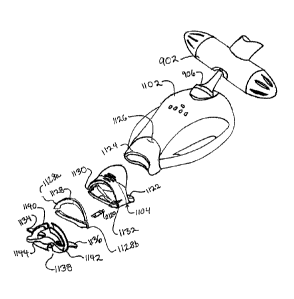
FIG. 3 is an exploded view of a lamp head according to
one embodiment of the invention. In the illustrated embodiment,
a light source 300 includes a first reflector 302.
The lamp
subassembly 130 has a heat sink 320-1, 320-2 to be coupled to
the light source ballast/base 322.
A fan 324 located in the
lamp head housing 104 in proximity to the heat sink 320 and
ballast/base 322 further acts to keep the source 300 and lamp
subassembly 130 cool. The heat sink may be made of any material
that has good thermal conductivity, including metal blocks of
copper, aluminum or similar. In another embodiment, the cooling
system includes heat pipes. In another embodiment, the cooling
system includes phase change materials, some embodiments and
material are exemplified as is described in U.S. Application No.
10/XXX,XXX, entitled "Dental Light Devices Having an Improved
Heat Sink" to be concurrently filed; and U. S. Provisional
Application No. 60/585,224, entitled "Dental Light Devices With
Phase Change Material Filled Heat Sink", filed on 7/2/2004, the
contents of which are incorporated herein by reference.
42
CA 02511277 2005-06-30
Customer No. / Attorney Docket No.: 000053096 / D2000-0004-P002
[00188] Heat sinks having a phase change material may more
efficiently remove or divert heat from a light source or sources
with a given weight of heat sink material when compared to a
heat sink made of a solid block of thermally conductive material
such as metal. Such a heat sink may even efficiently remove or
divert heat from a curing light device when a reduced weight of
the material is used. Using a phase change material enclosed
inside a hollow thermally conductive material such as a metal
heat sink instead of a conventional solid metal heat sink can
decrease the weight of the curing light and increase the time
the heat sink takes to reach the "shut off" temperature, as it
is called in the dental curing light industry. The period prior
to reaching the shut off temperature is called the "run time".
Increasing the "run time", i.e., the time that the light can
remain on, increases the time when a dentist can perform the
curing or whitening procedure.
[00189] In one embodiment, a rechargeable dental curing light
including at least one phase change material is disclosed. In
another embodiment, a dental whitening light including at least
one phase change material is disclosed. The heat sink includes a
block of thermally conductive material, such as metal, having a
bore or void space which is at least partially filled with a
phase change material.
001.90] The heat sink may be constructed by hollowing out a
thermally conductive material, such as metal, and at least
partially filling the void with at least one phase change
material prior to capping it to secure the phase change material
inside, such that the at least one phase change material is
substantially contained or surrounded by a thermally conductive
material such as metal normally used in the construction of a
conventional heat sink.
43
CA 02511277 2005-06-30
Customer No. / Attorney Docket No.: 000053096 / D2000-0004-P002
[00191]
Alternatively, the heat sink may be cast or machined
from a thermally conductive material, such as metal, to create
walls surrounding a bore or void. The bore or void is partially
filled with at least one phase change material prior to capping
it to secure the material inside.
[00192]
In one embodiment, the inventive heat sink may be used
by itself. In another embodiment, it may be used in addition to
a fan, in conjunction with a conventional metal block heat sink
or combinations thereof.
[00193]
The inventive heat sink may be installed into the
dental curing light, imaging or whitening light source in the
same manner a conventional metal block heat sink is installed,
such as by attaching it to the heat generating source, i.e., the
light source, which may include any of the ones mentioned above
or combinations thereof, or by attaching it to another heat
sink.
[00194]
Suitable phase change material may include organic
materials, inorganic materials and combinations thereof. These
materials can undergo substantially reversible phase changes,
and can typically go through a large, if not an infinite number
of cycles without losing their effectiveness. Organic phase
change materials include paraffin waxes, 2,2-dimethyl-n-docosane
(C24H50) trimyristin, ((C13H27000)3C3H3), and
1,3-methyl
pentacosane (C26H54). Inorganic materials such as hydrated salts
including sodium hydrogen phosphate dodecahydrate (Na2HPO4=12
H2O), sodium sulfate decahydrate (Na2SO4=10H20), ferric chloride
hexahydrate (FeC13-6 H20), and TH29 (a hydrated salt having a
melting temperature of 29 C, available from TEAP Energy of
Wangara, Australia) or metallic alloys, such as Ostalloy 117 or
UM47 (available from Umicore Electro-Optic Materials) are also
44
CA 02511277 2005-06-30
Customer No. / Attorney Docket No.: 000053096 / D2000-0004-P002
contemplated. Exemplary materials are solids at ambient
temperature, having melting points between about 30 C and about
50 C, more for example, between about 35 C and about 45 C. Also,
the exemplary materials have a high specific heat, for example,
at least about 1.7, more for example, at least about 1.9, when
they are in the state at ambient temperature. In addition, the
phase change materials may, for example, have a specific heat of
at least about 1.5, more for example, at least about 1.6, when
they are in the state at the elevated temperatures.
[00195] The phase change material may also have a high latent
heat of fusion for storing significant amounts of heat energy.
This latent heat of fusion may be, for example, at least about
30 kJ/kg, more for example, at least about 200 kJ/kg.
[00196] Thermal conductivity of the materials is a factor in
determining the rate of heat transfer from the thermally
conductive casing to the phase change material and vice versa.
The thermal conductivity of the phase change material may be,
for example, at least about 0.5 W/m C in the state at ambient
temperature and at least about 0.45 W/m C in the state at
elevated temperature.
[00197] In general, the phase change material may be contained
inside a thermally conductive material, such as a metal casing.
The casing defines a bore, which may be of any shape, but is for
example, generally of a cylindrical or rectangular shape. The
metal casing or wall of the bore acts to contain the phase
change material, and to also aid in conducting heat to and away
from the phase change material. The thinner the wall, the more
phase change material can be present in a given size of the heat
sink, and the less it contributes to the weight of, for example,
the curing light. However, the thinner the wall, the less
efficient the heat sink maybe in conducting heat away from the
CA 02511277 2005-06-30
Customer No. / Attorney Docket No.: 000053096 / D2000-0004-P002
phase change material and the longer it will take to return the
phase change material to ambient temperature and its original
state, so that it may function as a heat sink again. For
example, the wall thickness ranges from about 1 mm to about 2.5
mm, more for example, from about 1 mm to about 1.5 mm.
[00198]
The casing may also be constructed to have a large
surface area. A structure having fins or other features that
serve to increase the surface area for heat conduction or
convection is desirable, thus a spherical structure, though
useful, is not the optimal choice. Such fins or other surface
area increasing features may also be incorporated into the bore
to increase the contact area between the thermally conductive
casing and the phase change material, thus permitting faster
more efficient transfer of heat between the thermally conductive
casing and the phase change material.
[00199]
The thermally conductive casing can also provide a good
thermal contact for heat transfer from the light source. This
may be accomplished with a smooth, thermally conductive surface
with a high area of contact. Also, thermal coupling may be
achieved with thermally conductive interface materials such as
thermal epoxy. Interface materials that are electrically
insulating are also useful in isolating the light source from
the heat sink in an electrical sense without losing thermal
conductivity.
[00200]
The lamp subassembly 130 further includes a second
reflector 306-1, 306-2 located substantially coaxial with the
first reflector 302. The body of the second reflector 306
includes two tabs 309, 311. The tab 309 in the second reflector
upper portion 306-1 is bent downwards toward the bulb base 322
which provide additional protection to hold the light source 300
in place if the lamp head 102 is jarred or dropped.
In an
46
CA 02511277 2005-06-30
Customer No. / Attorney Docket No.: 000053096 / D2000-0004-P002
alternative embodiment, the tab 311 in the second reflector
lower portion 306-1 is bent upwards toward the bulb base 322 to
provide further protection. Typically, only one of the tabs is
bent in order to facilitate disassembly of the lamp head 102.
The second reflector 306 includes a reflective internal surface
326 adapted to further direct light toward the aperture 310 to
the target.
The reflective internal surface 326 is, for
example, a highly polished metal.
Other embodiments of the
second reflector 306 include anodized aluminum, and reflectors
formed by vapor deposition of dielectric layers onto metallic
layers, for example, a metallic layer on an anodized surface as
the base reflection layer, followed by deposition of a low
refractive index and then a high refractive index dielectric
layer, such as those available from Alanod, Ltd. of the United
Kingdom; a liquid crystal polymer plastic, one that can reflect
rather than transmit light energy, may be used, either as a
surface coating layer or as a main ingredient of the reflector,
as described above, or other materials with similar properties.
[00201] Typically, a liquid crystal plastic compound is
selected for a particular application based on one or more
factors including, for example, refractive indices,
processability, low absorption in the wavelength of interest,
ease of manufacture, ease of solvent removal, physical and
chemical properties (for example, flexibility, tensile strength,
solvent resistance, scratch resistance, and phase transition
temperature), and ease of purification.
[00202]
Suitable liquid crystal polymers include those suitable
for the lamp head housing mentioned above. Suitable polymers
include a chiral polyester, polycarbonate, polyamide,
polymethacrylate, polyacrylate, polysiloxane, or polyesterimide
backbone that includes mesogenic groups optionally separated by
rigid or flexible comonomers. Other suitable liquid crystal
47
CA 02511277 2005-06-30
Customer No. / Attorney Docket No.: 000053096 / D2000-0004-P002
polymers have a polymer backbone (for example, a polyacrylate,
polymethacrylate, polysiloxane, polyolef in, or polymalonate
backbone) with chiral mesogenic side-chain groups. The side-
chain groups are optionally separated from the backbone by a
spacer, such as an alkylene or alkylene oxide spacer, to provide
flexibility.
[00203] Typically, to form a liquid crystal layer, a liquid
crystal composition is coated onto a surface. The liquid crystal
composition includes at least one chiral compound (e.g., liquid
crystal plastic compound) or chiral monomer (liquid crystal
monomer) that can be used (e.g., polymerized or crosslinked) to
form a liquid crystal polymer plastic. The liquid crystal
composition can also include at least one nematic liquid crystal
compound or nematic liquid crystal monomer that can be used to
form a nematic liquid crystal polymer. The nematic liquid
crystal compound(s) or nematic liquid crystal monomer(s) can be
used to modify the pitch of the liquid crystal composition. The
liquid crystal composition can also include one or more
processing additives, such as, for example, curing agents,
crosslinkers, or ultraviolet, infrared,
antiozonant,
antioxidant, or visible light-absorbing dyes.
[00204] Liquid crystal compositions can also be formed using
two or more different types of any of the following: liquid
crystal plastics, liquid crystal monomers, nematic liquid
crystals, nematic liquid crystal monomers, or combinations
thereof. The particular ratio(s) by weight of materials in the
liquid crystal composition will typically determine, at least in
part, the pitch of the liquid crystal layer.
[00205] The liquid crystal composition also typically includes
a solvent. The term "solvent", as used herein, also refers to
dispersants and combinations of two or more solvents and
48
CA 02511277 2005-06-30
Customer No. / Attorney Docket No.: 000053096 / D2000-0004-P002
dispersants. In some instances, one or more of the liquid
crystal compounds, liquid crystal monomers, or processing
additives also acts as a solvent. The solvent can be
substantially eliminated from the coating composition by, for
example, drying the composition to evaporate the solvent or
reacting a portion of the solvent (e.g., reacting a solvating
liquid crystal monomer to form a liquid crystal polymer).
[00206] After coating, the liquid crystal composition is
converted into a liquid crystal layer. This conversion can be
accomplished by a variety of techniques including evaporation of
a solvent; crosslinking the liquid crystal compound(s) or liquid
crystal monomer(s); or curing (e.g., polymerizing) the liquid
crystal monomer(s) using, for example, heat, radiation (e.g.,
actinic radiation), light (e.g., ultraviolet, visible, or
infrared light), an electron beam, or a combination of these or
like techniques.
[00207]
In one embodiment, an optical lens 308 is disposed
within the second reflector 306.
According to this embodiment,
the optical lens 308 includes at least one curved surface and is
adapted to direct light towards a target. The lamp subassembly
130 further includes the integrator 312-1, 312-2 and a diffusing
element 330 which act together to provide uniform light directed
at a target (not shown).
[00208]
The optical path, or the interior of the lamp housing
104 of the lamp or illumination system may further include at
least one absorber/emitter having at least a portion that is
substantially transparent to the incident light, and at least
one portion capable of absorbing the incident light and emitting
light of a longer wavelength. In one embodiment, at least one
wavelength transformer may be configured to capture
substantially all the emitted light and transforming only a
49
CA 02511277 2005-06-30
Customer No. / Attorney Docket No.: 000053096 / D2000-0004-P002
portion of the captured light into a longer wavelength. In
another embodiment, at least one wavelength transformer may be
configured to capture at least a portion of the light emitted by
the light source and transforming all captured light into a
longer wavelength. The wavelength transformer may also be
present as a component of the light source 300, at least a
portion or component of the reflectors 302, 306, or the interior
of the lamp housing 104, as shown in FIG. 2.
[00209]
The wavelength transformer may also be adapted to
capture any lower wavelengths outside of the usable range of the
intended purpose and transforming it to a usable wavelength,
thus making use of the available output power and minimizing
extraneous heat generation.
[00210]
FIG. 4 is an exploded perspective view of the bottom
half of the lamp head housing 104 and the lamp subassembly 130
of FIGs. 2 and 3. The lamp subassembly 130 is assembled in this
view and includes the cooling components (the heat sink 320 and
fan 324), and the second reflector 306 and integrator 312. The
upper tab 309 in the second reflector 306 is shown in the
depressed mode in order to protect the light source as described
above. Further, the optical filter 314 is shown along with an
elastomeric mounting 332 for the optical filter 314.
When
assembled into the lamp subassembly 130, the optical filter 314
is coupled to the integrator 312 with the elastomeric mounting
332. Also shown in this FIG. is the electromechanical connector
334 that couples the lamp system to the electronics in the light
guide. This portion of the lamp system 100 will be described in
greater detail below.
[00211]
FIG. 4a shows the assembly of the second reflector 306
and integrator 312 in additional detail.
According to the
illustrated embodiment, the second reflector 306 and integrator
CA 02511277 2005-06-30
Customer No. / Attorney Docket No.: 000053096 / D2000-0004-P002
312 form a substantially rectangular pipe or box. As shown, the
reflector includes first 5020 and second 5040 reflective
internal surfaces.
[00212]
In the illustrated embodiment, the lower portion 305
and upper portion 307 of the second reflector 306 are adapted to
fit to one another at corresponding edges 5060, 5080 and 5100,
5120. According to one embodiment of the invention, the lower
portion 305 and upper portion 307 each include respective tabs
5140, 5160, 5180 (not shown) and 5200 to facilitate this
connection. Each tab 5140, 5160, 5180, 5200 includes a
respective surface (e.g., 5220) adapted to be mutually supported
against the respective tab of the opposing member.
[00213]
Like the second reflector 306, the integrator 312 is
formed, in the illustrated embodiment, of two portions 313 and
315.
Each of these portions includes respective mutually
supporting edges 5240, 5260, 5280 and 5300, and surfaces 5320,
5340, 5360 and 5380.
[00214] The reflector portions 5100, 5120 each have a
substantially trapezoidal internal surface region 5400, 5420.
In addition, the joining of the mutually supporting edges forms
additional substantially trapezoidal surface regions 5430, 5440.
[00215]
In like fashion, the integrator portions 313, 315 are
joined during assembly.
According to one embodiment of the
invention, this results in substantially rectangular surface
regions 5520, 5540 and substantially trapezoidal surface regions
5560, 5580.
In another embodiment of the invention, surface
regions 5520 and 5540 are substantially trapezoidal.
51
CA 02511277 2005-06-30
Customer No. / Attorney Docket No.: 000053096 / D2000-0004-P002
[00216]
According to a further aspect of the invention, the
reflector portions 5100, 5120 and integrator portions 313, 315
are joined at respective edges 5600, 5620 to form the above-
mentioned substantially rectangular pipe or box. According to
one embodiment of the invention, one or both of the reflector
306 and integrator 312 includes projecting tabs 5640 at their
mutually supporting edges. These tabs 5640 may be integral to
the respective assembly portions, or may be assembled thereto.
According to one embodiment of the invention, the tabs 5640
serve to interleave with each other, or with the opposite
member, and thus to more effectively couple the reflector 306 to
the integrator 312.
[00217] Because the light wavelengths most effective for
imaging, for chemical activation of a dental whitening compound
or other dental composition, may be deleterious to soft tissues,
it is desirable to minimize the exposure of a patient's gums,
tongue, facial skin and other soft tissues to the subject
illumination.
Therefore, properly controlling the light path
and focus of the applied illumination is important.
[00218]
In addition, in order to produce predictable, and
therefore optimizable results, it is important that the
intensity of the illumination received at a target composition
be substantially spatially and uniform. Also, the above-noted
desirability of limiting light exposure to the target
composition motivates a further aspect of the invention in
relation to fixturing of the light source and target area, also
noted above.
[00219]
FIG. 5 is an exploded perspective view of the lamp
system according to one invention embodiment.
According to
various embodiments of the invention, the lamp head 102 is
removably attached to the boom 108. The boom 108 is removably
52
CA 02511277 2005-06-30
Customer No. / Attorney Docket No.: 000053096 / D2000-0004-P002
attached to the mast 110. The mast 110 is removably attached to
the base 112. The power pack 114 is removably attached to the
mast 110.
The attachment mechanisms for each piece will be
described in greater detail below. The ability to separate each
of the lamp system main elements, that is, the lamp head 102,
the boom 108, the mast 110, the base 112 and the power pack 114,
from lamp system 100 provides advantages in shipping,
transportation and maintenance.
[00220]
The separated and/or modular lamp pieces are easier to
pack in a shipping crate than the lamp system 100 assembled.
Further, those pieces that require greater protection such as
the lamp head 102 may be packed in a more protective container
than the other pieces thereby protecting the more delicate
pieces of the lamp system 100 while minimizing shipping costs.
[00221]
The separated lamp system pieces are also easier to
transport than a fully assembled lamp, as, for example, by a
salesperson making customer visits.
Further, the ability to
separate the lamp system pieces enables individual pieces to be
shipped to a repair center for repair or for upgrade.
For
example, the lamp head 102 may be shipped to a repair center for
light source replacement.
[COM]
Figure 6 is a perspective view of a lamp head 102
according to one embodiment of the invention. The lamp head 102
includes the lamp head housing 104 and the light guide 106. The
lamp head housing 104 produces and directs light through the
light guide 106.
In the present embodiment, the lamp head
housing 104 produces light with a light source such as a bulb or
any of the light sources previously described.
The light guide
106 may serve as an interface between the lamp system 100 and
the patient having a dental treatment, such as whitening, to be
described in greater detail below with regard to FIG. 16.
53
CA 02511277 2005-06-30
Customer No. / Attorney Docket No.: 000053096 / D2000-0004-P002
[00223]
The lamp head housing 104 further includes two types of
lighted indicators 150, 152. The first type 150 indicates the
portion of the dental whitening process that has been completed.
In this embodiment, there are four such lighted indicators 150-
1, 150-2, 150-3, and 150-4.
Each of these indicators 150-1,
150-2, 150-3, and 150-4 shows that a portion of the whitening
process has been completed.
For example, for an hour-long
whitening process, a first 150-1 of these indicators is lit
after fifteen minutes. After thirty minutes a second indicator
150-2 is lit, and so on until the hour is passed at which point
all indicators 150-1, 150-2, 150-3, and 150-4 are lit.
In an
alternative embodiment of the invention, the lamp head housing
104 includes an indicator system in which a lighted indicator
blinks at selected intervals to indicate the percentage of the
whitening process that has been completed.
In another
alternative embodiment of the invention, a display mounted in
the lamp head housing 104, such as a liquid crystal display,
indicates the status of the whitening process.
Konq
The second type of lighted indicator is a single
indicator 152 that indicates a need for a new light source in
the lamp head housing 104, hereafter referred to as the light
source replacement indicator 152.
The mechanism by which the
light source replacement indicator 152 is activated will be
described below with respect to FIG. 35.
[00225]
In the illustrated embodiment of the lamp head housing
104, the lighted indicators 150, 152 are lit with LEDs.
In a
first alternative embodiment, the LEDs protrude through the
surface of the lamp head housing 104. In a second alternative
embodiment, the top surface of the lamp head housing 104 may be
sealed and/or smooth and the LEDs are positioned in recesses in
the undersurface of the lamp head housing 104. The material of
54
CA 02511277 2005-06-30
Customer No. / Attorney Docket No.: 000053096 / D2000-0004-P002
the lamp head housing 104 in the vicinity of the LED may be
transparent or translucent. This embodiment has the advantage
that the surface of the lamp head housing 104 is easier to clean
and also does not collect debris as would occur if there were
protrusions in the lamp head housing surface.
In a third
alternative embodiment, the lamp head housing surface has
markings positioned over the lighted indicators of the second
embodiment.
[00226]
In another embodiment of the invention, a control
system having a built-in voice alert system for alerting a
dental professional of the time, or stage, in a dental procedure
may be included. The control system may also include a headphone
or other private listening device, for example, so that only the
dental professional will receive the voice alert. In one aspect,
the private listening device may be a wireless listening device
such as a wireless radio channeling device or an infrared
channeling device.
[00227]
In one embodiment, a dental light system includes a
built-in electronic voice alerting system to alert the dental
professional of the completion of a dental procedure.
[00228]
In one aspect, the electronic voice alerting system may
utilize an electronic voice generating circuit technology,
similar to the technology used in electronic devices such as
toys, cell phones, automobiles and other consumer electronics,
but with novel message content that is directed to dental
applications.
[00229]
In still another embodiment, a dental illumination
system includes an audible electronic voice alert system having
a novel approach to tracking time during the above mentioned
dental procedures and other similar dental procedures. This
CA 02511277 2005-06-30
Customer No. / Attorney Docket No.: 000053096 / D2000-0004-P002
audible electronic voice alert system uses an electronic device
with prerecorded time interval statements stored in the device.
[00230] According to one embodiment, the alert system, in
addition to having the lighted indicators mentioned above, is
also adapted to play a recorded voice that is generated when an
electronic timer circuit is programmed to play the appropriate
electronic voice count alert through an audio speaker in the
device. In one aspect, the message played may include time
intervals, and may be programmed and in some embodiments, re-
programmed.
[00231] In a further embodiment, a dental lamp system having an
electronic timer device is controlled by a microprocessor with
an internal clock. The microprocessor receives a signal so as to
know when a lamp is first turned on. At predefined intervals of,
for example, five seconds, the electronic voice chip sends a
recorded audio signal to a speaker to announce elapsed and/or
remaining time to the user. In one embodiment of the invention,
the speaker is disposed within the light source. This process
may be programmed to continue and announce the ten second
intervals when the voice chip releases a different recorded
audio signal of "ten seconds". Various time increments and
corresponding audio signals can be programmed or selected
according to the requirements of a particular dental procedure.
[00232] In yet a further embodiment of the invention, a dental
lamp system includes a prerecorded audio stream that may be
configured to play a unique alert message at the end of a
procedure. The pre-recorded audio signal can include a message
such as "procedure complete", "end of a first cycle" when used
in chairside whitening procedures, or similar phrase.
Additionally, the system may be configured to give instruction
to the dental professional at certain times during the
56
CA 02511277 2005-06-30
Customer No. / Attorney Docket No.: 000053096 / D2000-0004-P002
procedure. Exemplary messages may include prerecorded audio
streams announcing, "the procedure is almost complete", "please
plan for the next step in the whitening process", and "whitening
lamp warm up cycle complete." Numerous and various such voice
alerts are possible and are intended to be within the scope of
this invention.
[00233]
In a yet still further embodiment, the invention,
includes a dental instrument having a voice alert system in any
of the above embodiments coupled to an electrical control
device. The electrical control device may include a
microprocessor and a switch such as an electromechanical switch
or a solid state switch. In various embodiments, the electrical
control device is adapted to both alert the dental professional
of the end of the procedure, and to also turn off the light
output, when the predetermined time period has expired. This may
further improve the efficiency and accuracy of a dental
procedure and free the dental professional to take care of other
matters within earshot of the voice alert system rather than
having to hover around the patient or be close at hand to turn
off the lamp. In one aspect, the alert system may be equipped
with a patient to dentist and/or dental practitioner call
device.
[00234]
The present embodiment of the lamp head 102 further
includes a formation such as a pivot mount 154.
This pivot
mount is also used if an illumination frame 105, such as that
shown in FIG. 10 described below, is used in place of the lamp
head 102. The pivot mount 154 is used to removably attach the
lamp head 102 to the boom 108. The pivot mount 154 includes a
shaft 156 and a ball swivel 158.
The shaft 156 of the pivot
mount 154 is attached at one end to the back of the lamp head
housing 104. The ball swivel 158 is attached to the other end
of the shaft 156.
The ball swivel 158 is inserted into a
57
CA 02511277 2005-06-30
Customer No. / Attorney Docket No.: 000053096 / D2000-0004-P002
spring-loaded ball cup on the boom 108 which will be described
in greater detail below with regard to FIG. 5. The pivot mount
154 enables the lamp head 102 to be swiveled around the end of
the boom 108 resulting in a high degree of freedom of movement
and therefore also improved ability to position the lamp head
102 with respect to the patient.
[00235]
FIG. 7 is a perspective view of the lamp head 102 and a
portion of the boom 108, further illustrating the removability
of the lamp head 102 from the boom 108. The lamp head 102 is
shown separated from the end of the boom 108, and includes the
lamp head housing 104 and the pivot mount 154. At the rear of
the lamp head housing 104 is a grill 160 having an electrical
connector 162.
[00236] The boom 108 has a lamp connector assembly 164.
The
lamp connector assembly 164 receives the ball swivel 158 of the
pivot mount thereby removably attaching the lamp head 102 to the
boom 108. As described above, this connection between the lamp
head 102 and the boom 108 allows a high degree of freedom of
movement of the lamp head 102 with respect to the boom 108.
Further, the boom 108 is a substantially hollow tube and may
contain I/O cables 166.
The I/O cables 166 include an
electrical plug 168 that is received by the electrical connector
162 in the lamp head housing 104 thereby removably attaching the
lamp head 102 to the boom electronically. The I/O cables 166
provide power to the lamp head 102 and also carry data and
control signals to and from the power pack 114.
[00237]
FIG. 7a shows, in perspective view, components of a
ball and socket joint according to one embodiment of the
invention.
The ball and socket joint (also referred to as a
ball joint) 902 includes a head tube 908 having a first opening
910 and a second opening 911 at opposite ends of the head tube
58
CA 02511277 2005-06-30
Customer No. / Attorney Docket No.: 000053096 / D2000-0004-P002
908. A third opening 912 is present in the side of the head
tube 908. The ball joint 902 further includes a first ball cup
914 and a second ball cup 915 to be received into the first and
second openings 910, 911, respectively. A pivot mount 906 that
holds the dental whitening lamp head (not shown) connects to the
ball joint 902 by a ball swivel 904. The first and second ball
cups 914, 915 are configured to receive the ball swivel 904
through the third opening 912 in the head tube 908. The ball
joint 902 will be described in more detail below.
[00238]
FIG. 8 is an exploded view of the lamp connector
assembly 900 enabling separable attachment between the lamp head
102 (not shown here) and the boom 103. The head tube 908 is
attached to the end of the boom 103.
The lamp connector
assembly 900 is a socket joint including a ball joint 902 that
receives the ball swivel 904 of pivot mount 906 on the lamp head
as shown below.
[00239]
The forward assembly 900 of the present embodiment
includes a first and a second ball cup 914, 915, a first and a
second spacer 916, 917, a first and a second spring 918, 919, a
first and a second nut plate 920, 921 and a first and a second
ball joint knob 922, 923. Each ball cup 914, 915 has a curved
surface so that when the ball cups 914, 915 are mated at the
curved surfaces a substantially spherically-shaped space
configured to receive the ball swivel 904 is formed.
[00240]
To form the ball joint, the ball cups 914, 915 are
inserted into the head tube 908 so that the spherically-shaped
space aligns with the third opening 912 of the head tube 908.
The spacers 916, 917 are inserted into openings 910 and 911
respectively and positioned on either side of the mated ball
cups 914, 915. The first and second springs 918, 919 are placed
against the first and second spacers 916, 917 respectively.
59
CA 02511277 2005-06-30
Customer No. / Attorney Docket No.: 000053096 / D2000-0004-P002
[00241]
The nut plates 920, 921 are attached on opposing ends
of the head tube 908 over the first and second openings 910,
911. The nut plates 920, 921 each may have a central opening
918, 919 that may be threaded.
[00242]
According to one embodiment of the invention, each of
the knobs 922, 923 may include an ultrasonically welded stud
having an externally threaded distal end.
The screws of the
knobs 922, 923 are screwed through the central openings of the
nut plates 920, 921 and press against the springs 918, 919,
spacers 916, 917, and ball cups 914, 915 to press the ball cups
914, 915 against the ball swivel 904. When the knobs 922, 923
are tightened down, the received ball swivel 904 may not move
inside the mated ball cups 914, 915.
When the knobs 922, 923
are loosened, the received ball swivel 904 may move inside the
mated ball cups 914, 915.
[00243]
A first alternative embodiment of the ball socket
involves relying on spring strength rather than pressure from a
screw to put pressure against the ball cups 914, 915. Further,
the springs 918, 919 shown here are coil springs. Alternatives
to coil springs include, for example, spring washers, and other
mechanisms for applying linear force, as known to those of skill
in the art.
[00244] FIG. 8a shows, in sectional perspective view,
components of a ball joint 902 shown with a cutaway view of the
head tube 908 according to one embodiment of the invention. The
first ball cup 914 is in place inside the head tube 908. The
ball swivel 904 of the pivot mount 906 is shown inserted through
the third opening 912 of the head tube 908.
CA 02511277 2005-06-30
Customer No. / Attorney Docket No.: 000053096 / D2000-0004-P002
[00245]
One of skill in the art will appreciate that a ball
joint, such as that illustrated, for example, in above FIGs. 8
and 8a, is merely exemplary of the various formations or
coupling features which may be used to couple a dental apparatus
or device to an end of the boom 903.
For example in an
alternative embodiment a flexible member, such as a gooseneck
member, is disposed between the payload apparatus and the
anterior end of the boom. The support structure of invention
may include any flexible coupling device appropriate to a
particular application and payload apparatus.
[00246]
FIG. 9 shows, in perspective view, a grill 160 for a
lamp head housing according to one embodiment of the invention.
In the illustrated embodiment, the grill includes a plurality of
perforations 131 between inner and outer surfaces thereof. The
perforations 131 are adapted to permit the passage of ambient
air between an interior region and an exterior region of the
lamp head housing, and thus allow for cooling and ventilation of
the housing.
In one embodiment, the perforations include a
plurality of substantially circular holes.
In other
embodiments, the grill may include square holes, rectangular
holes or slots, louvers, or another appropriate perforated
barrier such as, for example, a woven wire screen or appropriate
textile material.
[00247]
The grill of the illustrated embodiment includes two
flanges adapted to retain the grill in a substantially fixed
position at an aperture of the lamp head housing.
In the
embodiment shown, the flanges include an upper flange 132 and a
lower flange 133.
Each flange has a respective first lateral
134 and second elevated 135 portions disposed in angled relation
to one another.
61
CA 02511277 2005-06-30
Customer No. / Attorney Docket No.: 000053096 / D2000-0004-P002
[00248]
The angled relation between lateral 134 and elevated
135 flange portions includes, in various embodiments, a 900
angle or other angle suited to a particular application.
In
addition, the flange of a particular embodiment includes a barb
or latching profile or feature.
[00249]
As would be understood by one of skill in the art, the
elevated portions 135 include respective surfaces 136 adapted to
contact respective inwardly facing regions of the lamp head
housing so as to prevent displacement of the grill 160 when in
use. Although the illustrated embodiment includes flanges that
contiguously span a substantial portion of a width of the grill
alternative embodiments include a plurality of narrower flanges
spaced about a perimeter 137 of the grill.
[00250] It will be appreciated that, in various embodiments,
the flanges may be supplemented or replaced by alternative
coupling features such as snaps or fasteners.
According to
particular embodiments, such snaps or fasteners include one or
more rivets, including pop-rivets, machine screws, self tapping
screws, ball and socket pins, roll pins and cotter pins.
In
other embodiments, the grill is fixed in place by application of
a chemical adhesive such as, for example, epoxy, silicone
adhesive, contact cement, or cyanoacrylate based adhesive. In
still other embodiments of the invention, the grill is retained
in position by an elastomeric gasket and/or a magnetic coupler.
[00251]
According to the illustrated embodiment, the grill also
includes an electrical connector 162. The electrical connector
has a reinforced region 138. In the illustrated embodiment, the
reinforced region 138 is a removable member that is adapted to
be assembled to the balance of the grill. In another embodiment
of the invention, the reinforced region is integrally formed as
a portion of the grill.
62
CA 02511277 2005-06-30
Customer No. / Attorney Docket No.: 000053096 / D2000-0004-P002
[00252]
In one embodiment, the reinforced region 138 supports a
plurality of individual electrical connector pins 139.
In
various embodiments the individual electrical connector pins
include crimp-on connector pins such as, for example MolexTM
connector pins.
In another embodiment of the invention, the
individual connector pins are adapted to be soldered to
respective conductors, or integrally formed with those
respective conductors.
[00253]
In one embodiment of the invention, one or more of the
individual connector pins is a female receptacle.
In another
embodiment of the invention, one or more of the individual
connector pins is a male plug. One of skill in the art will
appreciate that a wide variety of alternative integrated and
individual connectors are possible, including connectors not
available at the time of conception, and that these various
connectors fall within the scope of the invention.
[00254]
According to one embodiment of the invention, the
individual connector pins are adapted to be inserted into pre-
formed bores within the reinforced region 138.
In another
embodiment of the invention, the reinforced region is adapted to
be formed, as for example by injection molding, with the
individual connector pins 139 molded in situ.
[00255] In the illustrated embodiment, each connector is
coupled to a respective conductor 161 so as to form respective
mechanical and electrical connections to the conductor 161.
According to one aspect of the invention, as illustrated, the
respective conductors are mutually coupled to a second
electrical connector 163 that is adapted to be disposed within
the lamp housing.
The second electrical connector includes a
63
CA 02511277 2005-06-30
Customer No. / Attorney Docket No.: 000053096 / D2000-0004-P002
plurality of electrical contacts for connection to, for example,
an internal circuit board of the lamp head.
[00256]
Multiple light sources, as shown in FIG. 10, may be
used in place of the above lamp head housing as a self-contained
structure, for example, an illumination frame, 105, in one
embodiment. As shown in FIG. 11a, the lamp head provides support
for the illumination system in one arrangement.
In another
arrangement, the lamp head provides power to the illumination
frame 105. In yet another arrangement, the lamp head is mounted
to an adjustable floor stand that provides further adjustability
for the dental illumination system, as shown in FIG. lla. In a
further aspect, the illumination frame may be in addition to the
lamp head housing, as shown in FIG. 11. In another embodiment of
the invention, the illumination frame may be mounted to a lamp
head, as is also shown in FIG. 11.
The dental illumination
system 100' includes an illumination frame 105 connected to a
lamp head 110' by a tube 115.
The illumination frame 105
provides light to activate a whitening substance or curing
composite applied to a patient's teeth 120.
The patient
typically wears a reference device, such as a lip retracting
device 350.
The illumination frame 105 and lamp head 110'
together generate and direct light toward the patient's teeth
120' for a whitening or a curing process. In one alternative
embodiment, the illumination frame 105 and tube 115 may be
adjustable with respect to the lamp head 110'.
In another
alternative embodiment, the tube 115 is flexible and may be
adjusted to various positions.
In another embodiment, the
illumination frame 110' is flexible.
[00257]
In the illumination system with multiple light sources,
the light sources may be collectively powered or individually
powered. If individually powered, each of the individual light
sources may be turned on or off separately, as desired. This is
64
CA 02511277 2005-06-30
Customer No. / Attorney Docket No.: 000053096 / D2000-0004-P002
especially useful for a curing or imaging process, where only
one or two teeth may be undergoing treatment or being examined.
[00258]
Multiple light sources may be arranged in a geometric
arrangement. In one embodiment, they may be arranged in an
arcuate form and may, for example, conform to the jaw of a
patient, as shown in FIG. 10. The illumination frame 105 has a
front 465 and a back 460. The front 465 is concave and the back
460 is convex. The tube 115 is attached to the back 230 of the
illumination frame 105. The tube 115 provides support for the
illumination frame 105 and also acts as a conduit for wiring for
the illumination frame 105. A plurality of light sources 235 is
arranged along the front 465 of the illumination frame 105. The
light sources may be any light source as described above. These
light sources are merely exemplary and are not limited to those
listed. The light sources 235 generate and direct light toward
the patient's teeth (as shown in FIG. 11) for a whitening,
imaging or a curing process. In a first embodiment, the light
sources 235 emit light having substantially the same light
spectrum.
In a second embodiment, the light sources 235 emit
light having different spectra.
In one aspect, the light
sources are approximately equidistant from the various teeth
toward which the light sources are directed. In another aspect,
the light sources 235 may protrude from the surface of the front
460 of the illumination frame 105.
In a further aspect, the
light sources 235 may be disposed substantially flush with the
surface of the front 460 of the illumination frame 105.
[00259]
FIG. 11a is a perspective view of an illumination
system 150' according to one embodiment.
The frame 105 is
attached by the tube 115 to the lamp head 110' which is attached
to an adjustable floor stand 155. In one aspect, the tube 115
is attached to the lamp head 110' by a pivotal joint 152', e.g.,
a ball joint.
In a first arrangement, the lamp head 110
CA 02511277 2005-06-30
Customer No. / Attorney Docket No.: 000053096 / D2000-0004-P002
provides power to the illumination frame 105 so that the
illumination frame 105 can generate light to activate a
whitening substance or a curing composite applied to a patient's
teeth. In a second arrangement, the illumination frame 105 and
lamp head 110' provides light for whitening, curing or imaging
by generating light at the lamp head 110' and directing it
through the illumination frame 105. In this embodiment, light is
provided to the illumination frame 105 through fiber optics
running through the tube 115.
[00260]
The illumination frame 105 may be similarly attached to
the mast, as described above. An exemplary embodiment is shown
in FIG. 11b, a perspective view of an illumination system 220
according to an embodiment of the present invention. The
illumination frame 105 is attached by the tube 115 to the
adjustable floor stand 155 directly rather than through a lamp
head 110' as seen in FIG. 11a. In this embodiment, the control
pack 190' is also a power pack.
This embodiment has the
adjustability of the system shown in FIG. ha but has less
weight due to the absence of the lamp head 110'.
[00261]
The illumination frame 105 has a first end 450 and a
second end 455, which may be tapered, as shown in FIG. 10-1, to
reduce the bulk of the side of the illumination frame 105 at the
patient's mouth.
[00262]
In one embodiment, the illumination frame 105 has a
plurality of light sources 235 that are substantially evenly
spaced across the surface of the front of the illumination frame
465, as exemplified in FIG. 10a. Other embodiments of the
invention have different arrangements of light sources 235
across the front 465.
For example, instead of being evenly
spaced, the light sources may be staggered.
The present
66
CA 02511277 2005-06-30
Customer No. / Attorney Docket No.: 000053096 / D2000-0004-P002
invention is not limited to the number and arrangement of light
sources 235 shown here.
[00263]
In FIG. 10b, the illumination frame 105 has a front 465
and a back 460. A tube 115 is connected to the back 460 and a
plurality of light sources 235 are arranged along the front 225
of the illumination frame 105.
In the embodiment shown, the
surface 240 of the front 225 of the illumination frame 105 is
non-reflective.
In a first embodiment, the surface 240 is a
non-reflective coating. In a second embodiment, the surface 240
is a layer of material such as a non-reflective plastic or
rubber.
[00264]
FIG. 10c is a rear perspective view of an illumination
frame according to one embodiment of the invention.
The
illumination frame 105 also has a front 225 and a back 460 with
a tube 115 attached to the back 460.
The tube 115 provides
support for the illumination frame 105 and also carries
electrical wiring for the light sources (not shown). The wiring
(not shown) is connected to an electrical connector 255 located
at the inside 250 of the tube 115.
[00265]
In another embodiment, as shown in FIG. 10d, the
illumination frame 105 has a generally rectangular shape and a
substantially flat front surface 500 with a plurality of light
sources 505 arranged along the front side 500. FIG. 10e is a
perspective view of an alternative arrangement of the
illumination frame of FIG. 10d. The illumination frame 105 has
a first slotted structure 520 on one end and a second slotted
structure 525 on the other end. Each slotted structure 520, 525
is disposed forwardly from the front side 500 of the
illumination frame 105.
The slots 530, 535 in each slotted
structure 520, 525 begin at respective front ends 540, 545 of
the slotted structures 520, 525 and are disposed inwardly toward
67
CA 02511277 2005-06-30
Customer No. / Attorney Docket No.: 000053096 / D2000-0004-P002
the front surface 500 of the illumination frame 105, and are
configured and arranged to mate with the formations, such as
wing-like members, of a reference device, such as a lip
retracting device 350, shown in FIG. 15 to facilitate alignment
of the illumination frame 105 with a patient's teeth.
[00266] In other embodiments of the invention, the illumination
frame 105 may be shaped and configured to mate with a reference
device such as a lip retracting device worn by the patient, such
as shown in FIG. 22a and 22b, thereby providing a substantially
precise alignment with the patient's mouth.
[00267] FIG. 10f is a top view of an illumination frame 105
including a heat sink according to one embodiment of the
invention. The illumination frame 105 has a plurality of light
sources 235, having a heat sink 650 coupled to their ballasts
(or, base). The heat sink 650 may be made of any material as
mentioned above, including a phase change material. The heat
sink may also be of any shape.
[00268] In some exemplary embodiments, for example, FIG. 12,
the illumination frame 105 may be attached to or disposed inside
a spacer, such as a light guide 106, having formations, such as
slots for engaging with a reference device, such as a lip
retracting device 1138, as shown in FIGs. 21a and b, also having
formations, such as wing-like members 111, for positioning the
illumination frame 105. An elastic member 1128 is disposed
between the patient and the light guide 106. The elastic member
1128 serves to cushion the interface between the patient and the
light guide 106, absorbing shocks which might otherwise be
painful or uncomfortable.
[00269] In another aspect, the illumination frame 105 may be a
self-contained structure, such as shown in FIGs. 10, 12, 13 and
68
CA 02511277 2005-06-30
Customer No. / Attorney Docket No.: 000053096 / D2000-0004-P002
14. In FIG. 13, the illumination frame 105 has a generally
arcuate shape having a first end 501 and a second end 502. The
back 230 of the illumination frame 105 is convex and the front
225 of the illumination frame 105 is concave. The illumination
frame 105 may also serve as the spacer having formations. In
other words, the spacer and formations, for example, slots, may
both be present on the lamp housing, such as the illumination
frame 105, as exemplified in FIG. 22b. The ends 500, 505 each
has a slot 510, 515 open from the front 225 of the illumination
frame 105 towards the back 230 of the illumination frame 105.
Each slot 510, 515, extends inwardly from its respective end
501, 502 of the illumination frame 105. The slots 510, 515 are
located and configured to mate with the formations of a
reference device, such as the wings 111 of a lip retracting
device 1138, as shown in FIGs. 21a and b.
[00270]
The light sources of the illumination frame 105 may be
of one wavelength, or may be of different wavelengths, as
mentioned above.
[00271]
As also noted above, the illumination frame 105 may
also include a pivot mount 154 and a ball swivel 158 at the end
of the shaft 156, as shown in FIG. 14. In another embodiment,
the illumination frame 105, such as that exemplified in FIG. 12,
may be attached to the support system of FIG. 1.
As noted
above, the boom 108 is adjustably positionable with respect to
the mast 110, as shown in FIG. 15.
The boom 108 has both a
rotational and a tilt range of motion with respect to the mast
110.
A counterweight 122 on the second end of the boom 108
provides a counterbalance for the illumination frame 105.
[00272]
The attachment is also similar to FIG. 7 above, and is
described below in the illustrated embodiment of FIG. 15a, where
69
CA 02511277 2005-06-30
Customer No. / Attorney Docket No.: 000053096 / D2000-0004-P002
the ball joint 902 is coupled to an illumination frame housing
1150. The housing 1150 includes a first elongate portion 1152
having at its posterior end the ball of the ball and socket
joint 902. A signal cable 1170 is coupled at one end to the
housing 1150.
The signal cable may include a power cable
adapted to provide power for the one or more illumination
sources 1156 disposed on front face 1154. The single cable may
also include an optical light guide such as an optical fiber
adapted to transmit light to the one or more illumination
sources from a remote light source. In at least one embodiment
of the invention, the signal cable 1170 includes a strain-relief
feature 1172.
[00273]
The embodiment of FIG. 15a shows first and second
formations, such as wing-coupling members 1158, 1160.
Each
wing-coupling member 1158, 1160 includes a respective slot 1162,
1164. The slots 1162, 1164 are adapted to receive corresponding
wing-like members 1134, 1136 of a reference device, such as a
lip retracting device described below.
[00274]
As noted above, the spacer may be a light guide 1000,
as shown in FIG. 16, which includes an elliptically tubular
member 1020 having an axial cavity 1040 disposed between a front
aperture 1060 and a rear aperture 1080.
[00275]
As shown in the illustrated embodiment, a first edge
1010 of the tubular member defines a substantially elliptically
saddle shaped curve having a convex form in relation to a
generally horizontal portion 1100 thereof and a concave form in
relation to a generally vertical portion 1120 thereof.
In
addition, edge 1010 includes first and second substantially
horizontal slots 1140, 1160. According to one embodiment of the
invention, the slots 1140, 1160 are disposed substantially
coplanar with respect to one another and are disposed
CA 02511277 2005-06-30
Customer No. / Attorney Docket No.: 000053096 / D2000-0004-P002
substantially coincident with a major axis of the elliptically
saddle shaped curve that defines edge 1010.
[00276]
A rim 1180 extends radially inwardly from the edge 1010
to a second substantially elliptically saddle shaped curved edge
1200 (also referred to as the "second edge"). The second edge
1200 is disposed in substantially constant spatial relation to
edge 1010, whereby the rim 1180 has a substantially uniform
radial dimension over the length of edge 1010.
Edge 1200
defines an outer periphery of the front aperture 1060.
[00277]
At the rear end of the embodiment of FIG. 16, a third
edge 1300 defines another curve that is of an approximately
elliptically saddle shape. Edge 1300 is substantially concave
in form in relation to a generally horizontal portion 1320
thereof and is generally convex in form in relation to a
generally vertical portion 1340 thereof.
[00278]
According to one embodiment of the invention, curve
1300 defines the rear aperture 1080 of the light guide.
[00279]
According to one embodiment of the invention, the light
guide does not include a rim adjacent the rear aperture 1080.
[00280]
In one aspect of the illustrated embodiment, an outer
surface 1390 of the light guide is disposed between edge 1010
and edge 1300.
An inner surface 1360 of the light guide is
disposed in a substantially uniform spatial relation to outer
surface 1390 so as to define inward and outward boundaries of
the elliptically tubular member 1020.
[00281]
In one embodiment of the invention, outer surface 1390
includes a plurality of gripping features 1380 adapted to
71
CA 02511277 2005-06-30
Customer No. / Attorney Docket No.: 000053096 / D2000-0004-P002
improve the grip of an operator on surface 1390 during
manipulation of the light guide 1000.
In the illustrated
embodiment, the gripping features 1380 have a raised elongated
ellipsoid aspect. In another embodiment of the invention, the
gripping features include a plurality of substantially
hemispherical bumps.
In still another embodiment of the
invention, the gripping features include a plurality of zigzag
grooves. One of skill in the art will appreciate that a wide
variety of features may be disposed on surface 1340, so as to
enhance overall gripability of the light guide 1000.
[00282]
FIG. 17 shows a light guide 200 according to another
embodiment of the invention. The light guide 200 includes a rim
201 with an aperture 202 in a lower portion thereof.
The
aperture 202 opens inwardly from a front end of the light guide
200 into an elongated cavity 204 formed, in part, by the inner
wall 1360 of the light guide. According to one embodiment of
the invention, the cavity 204 is adapted to receive a recording
device 206 therein.
[00283]
According to one embodiment of the invention, the
recording device 206 includes an assembly having a printed
circuit board 208 with an electromechanical contact 210 and a
memory integrated circuit 212 disposed thereon. In one aspect,
the recording device 206 includes a first side 231 and a second
side 232. In the illustrated embodiment, the memory integrated
circuit 212 has a rear side 234. Pursuant to one embodiment of
the invention, the memory integrated circuit 212 is
substantially permanently fixed to the circuit board by, for
example, soldering, adhesive bonding, potting or other methods
for integrated circuit mounting as are known to those of
ordinary skill in the art.
72
CA 02511277 2005-06-30
Customer No. / Attorney Docket No.: 000053096 / D2000-0004-P002
[00284]
According to one embodiment of the invention, the
cavity 204 is defined by a plurality of surfaces, adapted to
support the recording device 206 substantially fixedly with
respect Co the light guide 200.
[00285]
In one embodiment of the invention, the recording
device 206 is supported in a position such that the electro-
mechanical contact 210 is disposed in an elevated and exposed
location within axial cavity 1040 of the light guide 200.
[00286]
This spatial relationship is shown more clearly in, for
example, FIG. 18 which shows a posterior perspective view of a
light guide 3000 having disposed on the internal surface 1360 a
first support member 3020 and a second support member 3040.
Support member 3020 includes a first bearing wall 3060 and
support member 3040 includes a second bearing wall 3080.
A
third support member 3100 includes a bearing top surface 3120.
[00287]
Turning once again to recording device 206 (as shown in
FIG. 17) one sees that recording device 206 is adapted to be
received within a region 3200 as shown in FIG. 18.
When
recording device 206 is disposed in region 3200, bearing surface
3060 is disposed adjacent to and supports edge 231. The bearing
surface 3080 is disposed adjacent to and supports edge 232 and
bearing surface 3120 is disposed adjacent to and supports an
underside surface (not shown) of recording device 206.
[00288]
As a further feature of light guide 3000, a surface
3300 is disposed in a generally vertical orientation. A further
surface is disposed in substantially parallel spatial relation
to surface 3300, and forwardly of the same.
73
CA 02511277 2005-06-30
Customer No. / Attorney Docket No.: 000053096 / D2000-0004-P002
[00289]
Further insight into recording device 206 and its role
in the invention is gained by reference to FIG. 19 which shows a
light guide 3500 according to one embodiment of the invention in
anterior elevation.
Specifically, FIG. 19 shows the further
bearing surface 3320 disposed in substantially parallel spatial
relation to surface 3300 (as shown in FIG. 18) as discussed
immediately above. Also shown are aperture 202 (as discussed
above in relation to FIG. 17), first bearing wall 3080 and
second bearing wall 3060 (as discussed above in relation to FIG.
18).
[00290]
FIG. 17a shows another embodiment of the light guide
106 of a generally ellipsoidal shape having a first opening 220'
at one end that attaches to the lamp head housing 104 and a
second opening 222' at the other end that interfaces with the
patient. The first opening 220' has extended edges 224', 226'
that extend substantially parallel to the long diameter of the
oval formed by the light guide 106.
[00291]
The extended edges 224', 226' form a curved interface
configured to mate with the lamp head housing 104. The light
guide 106 mechanically couples to the lamp head housing 104. A
first protrusion 228' on extended edge 224' and a second
protrusion 230' on extended edge 226' are configured to mate
with indentations on the lamp head 102 and act to hold the light
guide 106 to the lamp head housing 104. A first slot 236' and a
second slot 238' on opposing sides of the second opening 222' of
the light guide 106 may be configured to mate with a reference
device, such as a lip retracting device 1148, worn by the
patient as illustrated in FIGs. 21a and 21b described below to
align the lamp head 102 accurately with the patient.
[00292]
In one embodiment, an elastic protector 270 is mounted
around the second opening 222' of the light guide 106 to provide
74
CA 02511277 2005-06-30
Customer No. / Attorney Docket No.: 000053096 / D2000-0004-P002
a soft interface between the light guide 106 and the patient.
The elastic protector 270 may be made of any open-cell or
closed-cell foam, rubber or elastomer, such as described above
for the soft overlays, and is attached to the light guide 106 by
means of heat sealing or an adhesive. In some embodiments, the
elastic protector 270 may be present in pieces 272, 274, which
may again be attached to the light guide 106 by means of heat
sealing or an adhesive. Suitable adhesives may include, but are
not limited to, structure adhesives, hot melt adhesives,
pressure-sensitive adhesives, reactive adhesives or the like.
Alternatively, suitable adhesives may be acrylic-based,
polyurethane-based, epoxy-based, polyamide-based,
styrene
copolymer-based, polyolef in-based or similar.
Further, the
elastic protector pieces 272, 274 may also be integrally molded
onto the light guide 106.
[00293]
In the present embodiment, the elastic protector 270
is made in two pieces, an upper portion 272 and a lower portion
274, extending the slots 236', 238' of the light guide 106 so as
to accommodate the wing-like members of an exemplary lip
retracting device.
[00294]
According to one embodiment of the invention, a light
guide 106, such as that exemplified in FIG. 17a, is intended to
be a single-use item, used for one patient, or one time dental
whitening treatment, filling procedure, or imaging, and then
discarded. With this in mind, in the illustrated embodiment of
FIG. 17a, the light guide 106 further includes a memory
integrated circuit 246' disposed within a space 250' molded into
the underside of the light guide 106.
The memory integrated
circuit 246' stores a record of a duration of use signal
indicating how long the particular light guide has been in use.
The light guide memory integrated circuit 246' is part of a
CA 02511277 2005-06-30
Customer No. / Attorney Docket No.: 000053096 / D2000-0004-P002
system for ensuring that the light guide 106 is not improperly
reused.
[00295] The biocompostable or biodegradable polymers,
including those mentioned above, are particularly suited for
single use light guides.
[00296]
In operation, the light guide 106 is attached to the
lamp head housing 104.
The light guide 106 has both a
mechanical attachment mechanism (the slots 228', 230') as
described above and an electrical contact 248 between the light
guide memory integrated circuit 246' and electronics in the lamp
head housing 104.
The electrical contact 248' mates with a
conductive projection in the lamp head forming an electro-
mechanical connection that enables signaling between the light
guide memory integrated circuit 246' and electronics in the lamp
head housing 104.
[00297]
The light guide 106 is aligned with the patient's mouth
using the positionability of the lamp system 100 and whitening
treatment is administered. A signaling device within lamp head
102, or within the power pack, records duration of use of light
guide usage onto the memory integrated circuit 246'.
When a
light guide usage limit is reached, the lamp system 100
precludes activation of the light source 300 in the lamp head
housing 104 and the light guide 106 is replaced in order to
operate the lamp system 100.
[00298]
In an alternative embodiment of the light guide 106, no
elastic protector 270 is used to interface between the light
guide 106 and the patient. In further alternative embodiments
of the light guide 106, the contact between the light guide
memory integrated circuit 246' and electronics in the lamp head
102 is a magnetic contact. Alternatively, the memory integrated
76
CA 02511277 2005-06-30
Customer No. / Attorney Docket No.: 000053096 / D2000-0004-P002
circuit 246' may communicate with the lamp head 102 through
infrared radiation or through wireless radio signals or through
light from the visible portion of the electromagnetic spectrum.
[00299] One of skill in the art will appreciate that when
recording device 206 (as illustrated in FIG. 17) is disposed
inwardly of aperture 202, surface 234 of integrated circuit
memory device 212 is disposed adjacent to, and supported by
bearing surface 3320. Furthermore, referring again to FIG. 18,
one of skill in the art will appreciate that when recording
device 206 is thus disposed, electromechanical contact 210 will
be disposed in a region adjacent and rearwardly of bearing
surface 3120 and will be exposed within axial cavity 1040 from
above, below, and from a rearward direction.
[00300] The structure of a light guide may include a UV-
inhibiting material in order to protect the patient's skin from
ultra-violet light exposure. The light guide may be made of
similar material as that of the lamp housing 104 and lamp head
102 as described above. Additionally, like the lamp housing 104
and the lamp head 102, a liquid crystal polymer, one that
reflects rather than transmits light energy, may be used, either
as a coating or as the main ingredient of the light guide to
minimize escape of light energy.
[00301] For illustrative purposes, FIG. 20 shows a lamp head
400 which includes a housing 402 having an outer surface 404. A
forward end of the lamp head housing 402 includes an aperture
406 defined by an edge 408. In operation, light is emitted from
a light source within the lamp head housing 402 through the
aperture 406.
[00302] The housing 402 includes an intermediate edge 410
disposed in a curve about aperture 406 in a forward region of
77
CA 02511277 2005-06-30
Customer No. / Attorney Docket No.: 000053096 / D2000-0004-P002
the housing 402.
Forwardly of the intermediate edge 410, a
surface region 412 is recessed in relation to the balance of the
housing surface 404.
[0030]
According to one embodiment of the invention, the lamp
head 400 is adapted to removably interface with a light guide
such as that indicated, for example by reference 3000 in FIG.
18. Accordingly, surface region 412 is adapted to be disposed
adjacent to and to be supported by, internal surface 1360 of
light guide 3000. Likewise, rear edge 1300 of light guide 3000
is adapted to be disposed adjacent to and supported by edge 410.
[00304] In addition, according to one embodiment of the
invention, the housing 402 includes a top recess 414, and a
corresponding bottom recess (not shown). The top recess 414 is
adapted to receive a first detent projection 420 (as shown in
FIG. 18) disposed adjacent edge 1300 of light guide 3000.
In
like fashion, the bottom recess is adapted to receive a second
detent projection 422 as shown in FIG. 18.
[00305]
According to one embodiment of the invention, the
material of the light guide is sufficiently elastic to urge
detent projections 420 and 422 into their respective recesses,
whereby the light guide is removably retained in position with
axial cavity 104 disposed adjacent to aperture 406 out the lamp
head.
[003015]
According to one embodiment of the invention, when the
light guide (e.g., 3000) is so disposed, the electromechanical
contact 210 (as shown in FIG. 17) is disposed within an
electrical plug on the lamp head. This is shown more clearly in
FIG. 20a, which includes a further recessed region 421 in
proximity to the front end 423 of the lamp head 400.
78
CA 02511277 2005-06-30
Customer No. / Attorney Docket No.: 000053096 / D2000-0004-P002
[00307]
As shown in FIG. 20b, this further recessed region 421
is disposed adjacent to the electrical plug referred to
immediately above, which is disposed behind an aperture 424 in
the housing 402 of the lamp head 400.
The aperture 424 is
adapted in size and shape to receive the electromechanical
connector 210, as shown in FIG. 17, therethrough.
[00308] As mentioned above, the interaction of detent
projections 420, 422 and corresponding recesses, e.g., 414 of
lamp housing 400 served to maintain the light guide in position
on the lamp housing once it is installed there until it is
actively removed.
[00309]
A plurality of light guides having output ends of
varying sizes corresponding to varying mouth sizes may be
provided.
[00310]
As also noted above, it is desirable to position and
orient the lamp head in substantially fixed relation with
respect to a target of the lamp's illumination, such as a tooth.
For example, during a dental whitening process, it is desirable
to maintain the distance and orientation between illumination
source fixedly contained within the lamp head and a target tooth
bearing a whitening compound, so as to maintain substantially
uniform illumination intensity over the target tooth both
spatially and during the duration of a whitening procedure.
[00311]
One way of accomplishing this objective is through the
use of a reference device, such as a lip retracting device 10,
as shown in FIG. 21, which is adapted to also retract the upper
and lower lips (herein "lips") for facilitating examination
and/or treatment of the mouth and/or teeth provided in
accordance to one practice of the present invention. The lip
79
CA 02511277 2005-06-30
Customer No. / Attorney Docket No.: 000053096 / D2000-0004-P002
retracting device 10, which may be also known as a tongur cup,
includes four spaced apart channel retainers 12, 14, 16, 18,
also known as flanges, for retaining four corresponding portions
of the lips for examination and/or treatment of the mouth or
teeth. When used, the lip retracting device 10 draws back the
lips, which retracts the cheeks, to expose the mouth so that a
health care professional can more easily see the teeth and work
on the teeth and/or mouth.
[00312]
The four channel retainers include two side channel
retainers 12, 14 for retaining the ends of the lips,
approximately where the upper and the lower lips intersect, and
two lip channel retainers 16, 18 for retaining the mid-section
of the upper and lower lips.
More particularly, the four
channel retainers or flanges 12, 14, 16, 18 are adapted to cup
the lips and bias them open to expose the teeth for treatment
and/or examination.
[00313]
A plurality of resilient members 20 are incorporated in
the lip retracting device 10 to interconnect the four channel
retainers 12, 14, 16, 18 together and to function as biasing
means.
In the ready position (before insertion of the lip
retracting device into the mouth), the resilient members 20 are
arched outwardly with respect to the center portion of the lip
retracting device 10. As further discussed below, when the lip
retracting device 10 is inserted into the mouth and the four
channel retainers 12, 14, 16, 18 cup respective portions of the
lips, the resilient members 20 provide a retractive force to
retract the lips radially outwardly for examination and/or
treatment.
[00314]
An optional tongue retainer 22 is shown approximately
centrally positioned relative to the four channel retainers 12,
14, 16, 18.
The tongue retainer may also be positioned
CA 02511277 2005-06-30
Customer No. / Attorney Docket No.: 000053096 / D2000-0004-P002
asymmetrically about the two channel retainers 16 and 18. The
tongue retainer 22 comprises a trough 23 and is attached to two
channel retainers 12, 14 by a pair of secondary resilient
members 24. When incorporated, the tongue retainer 22 and the
secondary resilient members 24 cooperate to block the tongue and
limit the tongue to the back vicinity of the mouth, thus
enabling access to the lingual portion or back of the teeth for
examination and/or treatment. In short, the tongue retainer is
configured to minimize interference by the tongue during
treatment and/or examination by a health care professional.
[00315] The side channel retainers 12, 14 resemble a
curvilinear c-channel in that they include an arcuate race 26
and two channel side walls 28a, 28b.
The channel side walls
28a, 28b resemble a bell shape and include a maximum wall
dimension at approximately the mid-point 34 and two smaller
tapered tips 36 at the ends thereof.
In one embodiment, the
inside side wall 28a, which is intraoral, as further discussed
below, may be slightly larger relative to the outside side wall
28b. However, the relative dimensions may be reversed or may be
the same without deviating from the functionality of the lip
retracting device 10.
[00316]
The side channel retainers 12, 14 further include an
interior surface 30 and an exterior surface 32.
The arcuate
race 26 comprises a radius of curvature 31 adapted to mimic the
curvature of the side of the lips when the lips are in the
opened position. Because this curvature may vary depending on
the size and age of the user or patient, the lip retracting
device 10 may be implemented with varying radius of curvatures
31 to fit the varied shape of the particular user/patient. The
arcuate race 26 may also include an irregular curvature or two
or more different radii of curvatures. For example, the lower
region 38 of the radius of curvature 31 may have a larger radius
81
CA 02511277 2005-06-30
Customer No. / Attorney Docket No.: 000053096 / D2000-0004-P002
than the upper region 40 or vice versa.
If implemented, the
irregular curvature can vary the amount of retraction of the
portion of the lip seated within the arcuate race to vary the
amount of retraction between those portions of the lip. The two
lip channel retainers 16, 18 may also have different radii of
curvatures, similar to the side channel retainers 12, 14.
[00317]
The lip channel retainers 16, 18, like the side channel
retainers 12, 14, resemble a curvilinear c-channel in that they
include an arcuate race 42 and two channel side walls 44a, 44b.
In one embodiment, the radius of curvature 46 of the lip channel
retainers is larger than the radius of curvature 31 of the side
channel retainers 12, 14.
The larger radius of curvature 46
enables the lip channel retainers 16, 18 to conform to the
contour of the upper and lower lips near the frenum, which is
more planar relative to the side of the lips. Depending on the
size and age of the intended user/patient, the radius of
curvature 46 of the lip channel retainer 16, 18 may also vary.
[00318]
As shown, a frenum release 48 is incorporated in the
inside side walls 44a of the lip channel retainers 16, 18 for
providing relief to the frenum of the upper and lower lips. In
one embodiment, the frenum release 48 includes a partial oval
shaped cutout having a size sufficient to provide clearance for
the frenum.
In other words, the frenum release 48 should be
such that the lowest most portion 50 of the frenum release only
slightly touches the frenum when in use, and for example, does
not touch the frenum. Although the oval shaped cutout is shown
for the frenum release 48, a partial circle, a rectangular
cutout, a square cutout, or other geometrical shaped cutout may
also be incorporated without deviating from the function of the
frenum release.
82
CA 02511277 2005-06-30
Customer No. / Attorney Docket No.: 000053096 / D2000-0004-P002
[00319]
The lip retracting device 10 may be made by injection
molding or casting a thermoplastic material such as
polypropylene, polyethylene, polystyrene,
polyester,
polycarbonate or the like.
The lip retracting device 10 may
also be made out of biocompostable or biodegradable polymers
mentioned above. More for example, the lip retracting device 10
may be made by injection molding polypropylene and may have a
smooth and transparent finish.
[00320]
As shown in FIG. 21b, two wing-like flanges 111 may be
incorporated in the lip retracting device of FIG. 21.
These
wing-like flanges 111 may be permanently attached by an adhesive
or by heat sealing, or molded or cast integrally with the side
channel flanges or retainers 12, 14, and may be constructed of
the same or different material as the channel flanges or
retainers, including the materials mentioned above.
An
exemplary illumination system is shown in FIG. 32, which is an
exploded view of the combination of a lip retracting device
1138, a light guide 1104 and a lamp system 1102. The wing-like
flanges 111 are designed for fitting into a pair of slots 1130,
1132 formed in the output port or light guide 1104 of a lamp
system 1102 used in a whitening process or to the slots in any
examination device. Another exemplary illumination system and
the use of which is disclosed in Ser. No. 10/715,681, filed
November 17, 2003, which is expressly incorporated herein by
reference as if set forth in full.
[00321] In another embodiment, instead of a light guide 1104,
an examining device such as a cone-like structure, as mentioned
above, may be configured to fit over the outlet of the lamp
system 1102 and the wing-like flanges 111 on the lip retracting
device 1138 may be configured to interact with the slots on the
cone to thereby provide a consistent and controlled gap between
83
CA 02511277 2005-06-30
Customer No. / Attorney Docket No.: 000053096 / D2000-0004-P002
the lamp system and the teeth of the patient to be treated or
examined. The wing-like flanges 111 may be constructed in the
manner shown and described above for the wing-like flanges with
reference to FIGs. 21a and 22.
[00322]
Referring now to FIG. 21a, there is shown another
embodiment of a lip retracting device 10' for retracting the
lips for facilitating examination of the mouth and/or teeth, the
whitening or curing process. The device includes two spaced
apart channel retainers 12', 14 , also known as flanges, for
retaining two corresponding portions of the lips for examination
and/or treatment of the mouth or teeth.
When used, the lip
retracting device 10' draws back the lips, which retracts the
cheeks, to expose the mouth so that a health care professional
can more easily see the teeth and work on the teeth and/or
mouth, similarly as shown in FIGs. 23 and 24.
[00323]
The two channel retainers 12', 14' are for retaining
the ends of the lips, approximately where the upper and the
lower lips intersect. More particularly, the two channel
retainers or flanges 12', 14' are adapted to cup the lips and
bias them in the open position to expose the teeth for treatment
and/or examination.
[00311]
A resilient member 20' is incorporated in the lip
retracting device 10' to interconnect the two channel retainers
12', 14' together and to function as biasing means.
The
resilient member 20' has two arches, one on either side of the
center portion 22'. The resilient member 20 may be formed as a
single piece integrally molded or attached to the inside side
walls 28a' of the channel retainers 12', 14', or it may be
formed in two halves separately connected to the mid-portion
22', also integrally molded or attached to the inside side wall
28a' of the channel retainers 12', 14'. In the ready position
84
CA 02511277 2005-06-30
Customer No. / Attorney Docket No.: 000053096 / D2000-0004-P002
(before insertion of the lip retracting device into the mouth),
the resilient members 20' are arched outwardly with respect to
the center portion of the lip retracting device 10'. As further
discussed below, when the lip retracting device 10' is inserted
into the mouth and the two channel retainers 12', 14' cup
respective portions of the lips, the resilient members 20'
provide a retractive force to radially retract the lips outward
for examination and/or treatment. This lip retracting device is
especially useful for the whitening process.
[00325] An optional tongue retainer 22' can also be
approximately centrally positioned relative to the two channel
retainers 12', 14'. Like the tongue retainer 22 of FIG. 21, the
tongue retainer 22' of the present embodiment may also include a
trough 23'. Further, it may be integrally formed on the mid-
portion of the resilient member 20' and thus be attached to the
channel retainers 12', 14' via resilient member 20'. When
incorporated, the tongue retainer blocks the tongue and limits
the tongue to the back vicinity of the mouth, thus enabling
access to the lingual portion or back of the teeth for
examination and/or treatment. In short, the tongue retainer is
configured to minimize interference by the tongue during
treatment and/or examination by a health care professional. In
this embodiment, the resilient member 20' acts not only to
connect the channel retainers and to bias them, but also to
connect the tongue retainer to the channel retainers.
If the
tongue retainer 22' is not incorporated, the resilient member
20' would simply extend from one channel retainer 12' to another
channel retainer 14' at a substantially uniform width.
[00326]
The channel retainers 12', 14' resemble a curvilinear
c-channel in that they include an arcuate race 26' and two
channel side walls 28a', 28b'.
The channel side walls 28a',
28b' resemble a bell shape and include a maximum wall dimension
CA 02511277 2005-06-30
Customer No. / Attorney Docket No.: 000053096 / D2000-0004-P002
at approximately the mid-point 34' and two smaller tapered tips
36' at the ends thereof.
In one embodiment, the inside side
wall 28a', which is intraoral, as further discussed below, is
slightly larger relative to the outside side wall 28b'.
However, the relative dimensions may be reversed or may be the
same without deviating from the functionality of the lip
retracting device 10'.
[00327]
The side channel retainers 12', 14' further include an
interior surface 30' and an exterior surface 32' and the
description of FIG. 21 above also applies here.
The arcuate
race 26' comprises a radius of curvature 31' adapted to mimic
the curvature of the side of the lips when the lips are in the
opened position.
Similarly, because this curvature may vary
depending on the size and age of the user or patient, the lip
retracting device 10' may be implemented with varying radii of
curvatures 31' to fit the varied shape of the particular
user/patient.
The arcuate race 26' may also include an
irregular curvature or two or more different radii of
curvatures. For example, the lower region 38' of the radius of
curvature 31' may have a larger radius than the upper region 40'
or vice versa. If implemented, the irregular curvature may vary
the amount of retraction of the portion of the lip that is
seated within the arcuate race to vary the amount of retraction
between those portions of the lip.
[00328]
The lip retracting device 10' may also be made by
injection molding or casting a thermoplastic material such as
those already mentioned. For example, the lip retracting device
10' may be made by injection molding pigmented polypropylene and
is opaque white or colored having a smooth finish.
[00329]
Additionally, FIG. 21a also shows two formations in the
shape of wing-like flanges 111 extending from the outside side
86
CA 02511277 2005-06-30
Customer No. / Attorney Docket No.: 000053096 / D2000-0004-P002
wall 28b' of the channel retainers 12', 14'.
The wing-like
flanges 111 may be molded or cast integrally with the channel
flanges or retainers 12', 14'. As further discussed below, the
wing-like flanges are designed for fitting the lip retracting
device 10' to the slots formed on a cone section of an output
port or light guide of a lamp source used in a teeth whitening
process, or to the slots in any examining device.
As an
example, FIG. 22 shows a bottom view of the lip retracting
device 10 with its wing-like flanges 111 engaging the slots on,
for example, a light guide 106, which is attached to a lamp head
104 shown in dash-dot lines.
[00330]
FIG. 22a shows a top view of a reference device such as
a lip retracting device 350 mated to an illumination frame 105
according to one embodiment of the invention.
The lip
retracting device 350 acts as a fixturing device for maintaining
the illumination frame 105 in substantially fixed relation with
respect to a target tooth.
As shown in the illustrated
embodiment, the lip retracting device 350 includes first 355 and
second 360 U shaped channels adapted to receive the lips of a
dental patient adjacent to respected internal surfaces 365, 370
thereof.
[00331]
FIG. 22b shows another embodiment of a lip retracting
device 350 mated again to an illumination frame 105. The lip
retracting device again mates directly to the light source
without an intervening light guide, such as is shown in FIG. 22,
where 106 is the light guide and 104 is the light source.
[00332]
FIG. 23 is a semi-schematic perspective view of an
alternative lip retracting device 10" provided in accordance to
another embodiment of the present invention. In one embodiment,
this alternative lip retracting device 10" is identical to the
lip retracting device 10 shown in FIGs. 21 and 21b, except that
87
CA 02511277 2005-06-30
Customer No. / Attorney Docket No.: 000053096 / D2000-0004-P002
this embodiment does not include a tongue retainer.
Accordingly, the description set forth above for the lip
retracting device 10 applies for the alternative lip retracting
device 10" less the tongue retainer.
[00333] Similarly, although not specifically shown, lip
retracting device in FIG. 21b, includes formations such as the
wing-like members 111, shown in FIG. 21b. These wing-like
members are adapted to be fitted to a light guide having
formations or an illumination frame having formations, as
discussed above.
[00334]
FIG. 24 shows is an exemplary semi-schematic top plan
view of the lip retracting device 10 of FIG. 21 in use on a
patient or user 84.
As shown, the lip retracting device 10
engages the user's mouth 86 to retract the user's lips 88 and
cheeks 90.
Once in position, the user's mouth 86, and
particularly the teeth 92, is exposed for examination and/or
treatment by a health care professional. More specifically, the
side channel retainers 12, 14 engage the side of the mouth, the
lip channel retainers 16, 18 engage the upper and lower lips 88,
and the resilient members 20 bias the four channel retainers,
which bias the lips 88 and cheeks 90 open, to expose the teeth
and the inside of the mouth 86.
In the lip retracting device
used position, the outside side walls 28b, 44b and the resilient
members 20 are exposed extraorally of the mouth.
[00335]
The tongue retainer 22 is shown also engaged to the
tongue 94 and relegates the tongue to the back region of the
mouth 86.
When incorporated, the tongue retainer 22 is
configured to further expose the lingual surface 96 of the teeth
for examination and/or treatment.
88
CA 02511277 2005-06-30
Customer No. / Attorney Docket No.: 000053096 / D2000-0004-P002
[003361
The lip retracting device 10 may be installed on the
lips 88 by first placing the upper lip over the inside side wall
44a and into the race 42 of the upper lip channel retainer 16.
The two side channel retainers 12, 14 are then squeezed together
and placed into the mouth, either concurrently or one at the
time, until the sides of the lips fit over the inside side walls
28a of the side channel retainers 12, 14 and into the race 26.
Finally, the lower lip channel retainer 18 is squeezed and
placed over the lower lip 88 with the lower lip engaging the
race 42 of the lip channel retainer 18.
Once installed, the
tongue retainer 22 automatically aligns with the tongue 94 to
block the tongue from maneuverability.
The lip retracting
device 10 may also be installed by reversing the steps discussed
above or squeezing all four channel retainers at the same time
and fitting the lips over the channel retainers.
[00337]
The formations such as wing-like members or flanges,
not shown here, but shown in FIG. 21b, may be made of the same
material as the rest of the lip retracting device or of a more
sturdy polymeric material or composite. Additionally, it may
also be opaque or colored even if the rest of the lip retracting
device may be colorless or clear.
[00338]
FIG. 24a shows a front view of a lip retracting device
350 of FIG. 25a being worn by a person. The interface wings 111
are located at either side of the lip retracting device 350 and
are available for mating with the imaging head, such as a light
source 102 as shown in FIG. 1.
[00339]
The lip retracting device 10' is configured to fit into
the mouth in the orientation shown in FIGs. 24 and 25. In other
words, in FIG. 25, the inside side walls 28a', and the tongue
retractor 22' are configured to be intraoral while the outside
89
CA 02511277 2005-06-30
Customer No. / Attorney Docket No.: 000053096 / D2000-0004-P002
side walls 28b', the resilient member 20' and the wing-like
members 111 are configured to be extraoral.
[00340]
FIG. 25a shows a lip retracting device 350 includes
first 355 and second 360 semicircular "U"-shaped channels
adapted to receive the lips of a dental patient adjacent to
respected internal surfaces 365, 370 thereof. This is similar to
FIG. 21a, but in a ready-to-use configuration.
In a ready to
use configuration, some of the structures takes on a different
form than the not ready to use mode. A support member 375 is
mutually coupled to the "U"-shaped channels 355, 360 and adapted
to support the "U"-shaped channels 355, 360 in substantially
fixed spatial relation with respect to one another. According
to one embodiment of the invention as shown in FIG. 21a, the
support member 375 also supports a tongue-cap adapted to retain
a patient's tongue and shield the same from incidental
illumination.
[00341]
According to one embodiment of the invention, a pair
of interface wings 111 is coupled to the "U"-shaped channels
355, 360 respectively. According to one embodiment of the
invention, the interface wings 111 each include a respective
upper surface 390, 395 and a respective lower surface 401, 403.
According to one embodiment of the invention, upper surface 390
is disposed substantially parallel in relation to lower surface
401 and upper surface 395 is disposed substantially parallel in
relation to lower surface 403. Pursuant to one embodiment of
the invention, the interface wings 111 have a first plurality of
ticks or holes 413 and a second plurality of ticks or holes 415
respectively.
The ticks or holes are adapted to facilitate
maintaining a particular alignment of, for example, an
illumination frame (as shown in FIG. 13) 105 with respect to the
lip retracting device 350.
CA 02511277 2005-06-30
Customer No. / Attorney Docket No.: 000053096 / D2000-0004-P002
[00342]
According to one embodiment of the invention, interface
wings 111 are adapted to be received within slots 236', 238' of
a light guide 106, as shown in, for example, FIG. 17a,
respectively. By pressing the lip retracting device 350 toward
the front edge of light guide 106, the interface wings 111 are
urged into slots 236' and 238', whereby the orientation and
position of the lip retracting device 350 with respect to the
light guide 106 is substantially fixed.
Consequently, to the
extent that a patient's lips effectively serve to couple the
head and teeth of the patient in fixed relation to the lip
retracting device 350, a target tooth is maintained in
substantially fixed position with respect to a light source
disposed within a lamp-head as shown, for example in FIG. 2.
[00343]
FIG. 25b shows a lip retracting device such as the lip
retracting device 350 of FIG. 25a mated to a light guide 106
according to one embodiment of the invention. FIG. 25b is a top
view of the mated light guide 106 and lip retracting device 350,
as FIG. 22, except that the light source is not shown or the
light source and the light guide may be integrally formed. The
holes 413, 415 again enable the mating of the light guide 106 or
the integral light guide and light source with the lip
retracting device 350 to be adjusted according to the patient.
[00344]
In FIG. 26, the lip retracting device 10' is shown as
it would appear inside a patient's mouth with all components
located inside the patient's mouth except for the wing-like
flanges 111 and the outside side walls 28b', which would be
outside the patient's mouth.
As is readily apparent, the
resilient member 20' is integrally molded to the inside side
walls 28a' to not interfere with the insertion of the lip
retracting device 10' into the mouth.
91
CA 02511277 2005-06-30
Customer No. / Attorney Docket No.: 000053096 / D2000-0004-P002
[00345]
Pads may be provided with the resilient member 20' to
provide comfort for the patient when the patient is fitted with
the lip retracting device 10'. The pads 107 may be positioned
on the resilient member 20', as shown in FIG. 27.
The pads
(FIG. 28) may be molded out of any foam material, such as those
described above for the soft overlays, which may be molded in
two halves connected along one edge, like a clam-shell, as shown
in FIG. 28. Each half may incorporate a slot, channel, or ridge
109 for receiving at least a portion of the resilient member
20'. The two halves may be fitted around the resilient member
and then heat sealed together. Other methods of assembly that
may achieve the same or similar results are also contemplated.
For example, the ridges 109 are so sized so that when the pad
107 is fitted over the resilient member 20', the pad is able to
slide relative to the resilient member to enable adjustment to
the location of the pad on the resilient member.
[00346]
For example, the pads 107 are made of polyethylene
closed-cell foam so that they may be sterilized.
Open cell
foams may also be used if they are amenable to autoclaving.
Also, the pads have, for example, a smooth outside surface and
smooth edges so that the pads may fit comfortably when in
contact with the inside of a patient's mouth without unwanted
irritation. In one embodiment, the pads may be designed to be
placed over the second to the last molar when the lip retracting
device 10' is inside a patient's mouth. In addition, they may be
made with, for example, relatively high resiliency material so
that they, for example, may return to their original shape after
use.
[00347]
In another embodiment, the pads 107 may be removable
after each use. Here, the pads may be attached using removable
adhesive or the two halves may simply be mated over the
resilient member using detents or the like. Any foam material
92
CA 02511277 2005-06-30
Customer No. / Attorney Docket No.: 000053096 / D2000-0004-P002
that may be made to fit comfortably inside a patient's mouth may
be used as alternatives. The two-halves of the pad may also be
made, for example, by heat set, to have a memory so that it may
be forced open for installation onto a resilient member and be
snapped shut when the opening force is removed. The two-halves
may be integrally molded or attached along at least one side.
[00348]
In a further embodiment, pads may be permanently
affixed and may not be sterilizable, making the lip retracting
device a one-patient use item.
[00349]
FIG. 29 shows another embodiment of a lip retracting
device 2000 of the present invention. The lip retracting device
2000 includes a first u-shaped channel 2010 shaped and
configured to accommodate a lower, or alternatively an upper,
set of a patient's teeth (not shown). The lip retracting device
2000 further includes a second u-shaped channel 2030 and a third
u-shaped channel 2050 mounted substantially perpendicular to the
first u-shaped channel 2010.
The second and third u-shaped
channels 2030, 2050 are adapted to receive the lips of the
dental patient.
The first u-shaped channel 2010 supports the
second and third u-shaped channels 2030, 2050 in substantially
fixed spatial relation with respect to one another.
[00350] According to the present embodiment of the invention,
a pair of interface wings 2020, 2040 is coupled to the second
and the third u-shaped channels 2030, 2050 respectively.
The
interface wings 2020, 2040 are shaped and configured to be
received into slots 1130, 1132 in a light guide 1104, fitted to
a lamp head or light source 1102, as shown in FIG. 32, in order
to align the light source 1102 with the teeth of a patient. To
the extent that a patient's lips effectively serve to couple a
lamp head and teeth of the patient in fixed relation to the lip
retracting device 1138, the lip retracting device 1138 is
93
CA 02511277 2005-06-30
Customer No. / Attorney Docket No.: 000053096 / D2000-0004-P002
maintained in a substantially fixed position with respect to a
light source disposed within a lamp-head as shown, for example
in FIG. 32. This is described in greater detail below.
[00351]
The interface wings or wing-like members, 2020, 2040,
like the wing-like members of the above described lip retracting
devices, typically have some rigidity so that the interface
wings 2020, 2040 may form an effective interface when mated with
the slots 1130, 1132 of the light guide 1104, as seen in FIG.
32. Similar to the embodiments described above, the interface
wings 2020, 2040 may in a first arrangement be formed of the
same material as the channels 2010, 2030, 2050.
In a second
arrangement, the interface wings 2020, 2040 are made of a
different material from the channels 2010, 2030, 2050.
[00352]
FIG. 29a shows a lip retracting device 550 according to
an alternative embodiment of the invention. The lip retracting
device 550 has a first u-shaped channel 552 and a second u-
shaped channel 554 to hold the lips of the patient whose teeth
are to be imaged. A support member 556 is mutually coupled to
the u-shaped channels 552, 554 and is adapted to support the u-
shaped channels 552, 554 in substantially fixed spatial relation
with respect to one another.
A first end 558 of the first
interface wing 562 is coupled to the first u-shaped channel 552.
A first end 560 of the second interface wing 564 is coupled to
the second u-shaped channel 554.
[00353]
Each interface wing 562, 564 includes a first portion
566, 568 located at the front of the lip retracting device 550
away from the patient.
A second portion 570, 572 of each
interface wing 562, 564 extends outward and toward the back of
the lip retracting device 550. In operation, the first portions
566, 568 are located at the front of the patient's face while
each second portion 570, 572 is located at a side of the
94
CA 02511277 2005-06-30
Customer No. / Attorney Docket No.: 000053096 / D2000-0004-P002
patient's face. The interface wings 562, 564 are adapted to be
received within the slots 236, 238 of the beam guide 106. The
first portions 566, 568 enable the beam guide 106 to be aligned
to the front of the patient. The second portions 570, 572 of
the interface wings 562, 564 enable the beam guide 106 and
imaging head 102 to be aligned on either side of the patient's
head.
[00354]
FIG. 29b shows a lip retracting device 600 according
to an alternative embodiment of the invention.
The lip
retracting device 600 has a first u-shaped channel 602 and a
second u-shaped channel 604 to hold the lips of the patient
whose teeth are to be imaged. A support member 606 is mutually
coupled to the u-shaped channels 602, 604 and is adapted to
support the u-shaped channels 602, 604 in substantially fixed
spatial relation with respect to one another. A first end 608
of the first interface wing 612 is coupled to the first u-shaped
channel 602. A first end 610 of the second interface wing 614
is coupled to the second u-shaped channel 604. The interface
wings 612, 614 are adapted to be received within the slots 236,
238 respectively of the beam guide 106.
A target 616, 618 is
coupled to a second end 620, 622 of the first interface wing 612
and second interface wing 614 respectively.
Each target 616,
618 has alignment markings 624. In operation, the targets 616,
618 act as visual alignment mechanisms for the imaging head 102
for side images of the patient's teeth.
[00355]
FIG. 29c shows a lip retracting device 6500 according
to an alternative embodiment of the invention.
The lip
retracting device 6500 has a first u-shaped channel 6520 and a
second u-shaped channel 6540 to hold the lips of the patient
whose teeth are to be imaged. A support member 6560 is mutually
coupled to the u-shaped channels 6520, 6540 and is adapted to
CA 02511277 2005-06-30
Customer No. / Attorney Docket No.: 000053096 / D2000-0004-P002
support the u-shaped channels 6520, 6540 in substantially fixed
spatial relation with respect to one another.
[00356]
A first end 658 of the first interface wing 6620 is
coupled to the first u-shaped channel 6520. A first end 6600 of
the second interface wing 664 is coupled to the second u-shaped
channel 6540. Each interface wing 6620, 6640 includes a first
portion 6660, 6680 located at the front of the lip retracting
device 6500 away from the patient. A second portion 5700, 5720
of each interface wing 6620, 6640 extends outward and toward the
back of the lip retracting device 6500. In operation, the first
portions 6660, 6680 are located at the front of the patient's
face while each second portion 6700, 6720 is located at a side
of the patient's face.
The interface wings 6620, 6640 are
adapted to be received within the slots 236, 238 of the beam
guide 106. The first portions 6660, 6680 enable the beam guide
106 to be aligned to the front of the patient.
The second
portions 6700, 6720 of the interface wings 6620, 6640 enable the
beam guide 106 and imaging head 102 to be aligned on either side
of the patient's head.
[00357]
A target 6740, 6760 is coupled to the second portions
6700, 6720 of the first interface wing 6620 and second interface
wing 6640 respectively.
Each target 6740, 6760 has visual
alignment markings 6780.
In operation, the targets 6740, 6760
act as visual alignment mechanisms for the imaging head 102 for
side images of the patient.
[00358]
FIG. 29d shows a lip retracting device 7000 according
to one embodiment of the invention. The lip retracting device
7000 is also a fixturing device for maintaining the imaging head
102 (as shown in FIG. 1) in substantially fixed relation with
respect to a target tooth. Further, the lip retracting device
7000 holds film inside the teeth of the patient in a manner in
96
CA 02511277 2005-06-30
Customer No. / Attorney Docket No.: 000053096 / D2000-0004-P002
which the patient does not actively participate in the holding.
In bite-wing images, for example, the patient must bite down on
a portion of the film holder in order to maintain the imaging
film in a proper position. For people with poor muscle control,
biting down for even a short period of time may be difficult. A
film holder 7020 attached to the lip retracting device 7000 as
described below does not require the active participation of the
patient to hold the film in place.
[00359]
As shown in the illustrated embodiment, the lip
retracting device 7000 includes first 7040 and second 7060
semicircular "U"-shaped channels adapted to receive the lips of
a dental patient as described above with respect to FIG. 25a. A
support member 7080 is mutually coupled to the "U"-shaped
channels 7040, 7060 and adapted to support the "U"-shaped
channels 7040, 7060 in substantially fixed spatial relation with
respect to one another.
According to one embodiment of the
invention, a pair of interface wings 7100, 7120 are coupled to
the "U"-shaped channels 7040, 7060 respectively. According to
one embodiment of the invention, interface wings 7100, 7120 are
adapted to be received within slots 236, 238 respectively (as
shown in FIG. 17a).
[00360]
The support member 7080 is shaped and configured to
support a film holder 7020. In one embodiment, the film holder
7020 is an integral part of the lip retracting device 7000. In
an alternative embodiment, the film holder 7020 is separably
coupled to the lip retracting device 7000.
With the lip
retracting device 7000 held in place by the patient's lips in
the u-shaped channels 7040, 7060, the film in the film holder
7020 is also held in place. The lip retracting device 7000 is
symmetric and accordingly the film holder could be located on
either side of the central portion 7140 of the support member
7080.
In an alternative embodiment of the invention, the
97
CA 02511277 2005-06-30
Customer No. / Attorney Docket No.: 000053096 / D2000-0004-P002
support member 7080 is configured to support two film holders
7020, one on either side of the central portion 7140 of the
support member 7080. In this embodiment, the front 7160 of the
film holder 7020 is x-ray penetrable while the back 7180 of the
film holder 7020 blocks x-rays.
In a first arrangement, the
front 7160 of the film holder 7020 is made of an x-ray
penetrable material while the back 7180 of the film holder 7020
is made of an x-ray blocking material. In a second arrangement,
an x-ray blocking lining is inserted behind the film in the film
holder 7020.
[00361]
FIG. 29e shows a lip retracting device 7500 according
to one embodiment of the invention. The lip retracting device
7500 is also a fixturing device for maintaining the imaging head
102 in substantially fixed relation with respect to a target
tooth. Further, the lip retracting device 7500 improves access
to the patient's mouth so that film may be inserted and removed
easily in order to make a series of images.
[00362]
As shown in the illustrated embodiment, the lip
retracting device 7500 includes first 7520 and second 7540
semicircular "U"-shaped channels adapted to receive the lips of
a dental patient.
A first support member 7560 is mutually
coupled to first ends 7580, 7600 of the u-shaped channels 7520,
7540.
A second support member 7620 is mutually coupled to
second ends 7640, 7660 of the u-shaped channels 7520, 7540. The
support members 7560, 7620 are adapted to support the u-shaped
channels 7520, 7540 in substantially fixed spatial relation with
respect to one another. The support members 7560, 7620 leave a
space between them that enables film to be inserted into the
patient's mouth for imaging purposes while the u-shaped channels
7520, 7540 hold the patient's lips clear.
98
CA 02511277 2005-06-30
Customer No. / Attorney Docket No.: 000053096 / D2000-0004-P002
[00363]
In the present embodiment of the invention, a pair of
interface wings 7680, 7700 are coupled to the "U"-shaped
channels 7520, 7540. The interface wings 7680, 7700 are adapted
to be received within slots 1140, 1160 respectively of the beam
guide 1000 (shown in FIG. 16) where the imaging head 102 is
located at the front of the patient.
In an alternative
embodiment, the interface wings 7680, 7700 are extended as in
the embodiment illustrated in FIG. 29a. The extended interface
wings enable the imaging head 102 to be positioned at either
side of the patient's head.
[00364]
FIG. 30 shows a lip retracting device 2100 having a
first u-shaped channel 2010 mutually coupled to a second u-
shaped channel 2030 and third u-shaped channel 2050 which are
substantially perpendicular to the first u-shaped channel 2010.
A tab 2060 is coupled to the first u-shaped channel 2010 between
the second and third u-shaped channels 2030, 2050. The tab 2060
is useful for positioning the lip retracting device 2100 in the
mouth of the dental patient.
Later, after completion of the
whitening process, the tab 2060 is useful for removing the lip
retracting device 2100 from the mouth of the dental patient.
[00365]
FIG. 31 is an alternative embodiment of the lip
retracting device according to principles of the invention. The
lip retracting device 2500 includes a lower jaw u-shaped channel
2510 and an upper jaw u-shaped channel 2520. The lower jaw u-
shaped channel 2510 is shaped and configured to accommodate the
lower set of the patient's teeth (not shown) while the upper jaw
u-shaped channel 2520 is shaped and configured to accommodate
the upper set of the patient teeth (not shown). Both the lower
jaw u-shaped channel 2510 and the upper jaw u-shaped channel
2520 are adapted to receive a treatment composition, such as a
whitening composition. The lip retracting device 2500 further
includes a first u-shaped lip retracting device channel 2530 and
99
CA 02511277 2005-06-30
Customer No. / Attorney Docket No.: 000053096 / D2000-0004-P002
a second u-shaped lip retracting device channel 2540. The first
and second u-shaped lip retracting device channels 2530, 2540
are mounted substantially perpendicular to the lower jaw u-
shaped channel 2510 and upper jaw u-shaped channel 2520. The
lower jaw u-shaped channel 2510 and upper jaw u-shaped channel
2520 support the a first u-shaped lip retracting device channel
2530 and a second u-shaped lip retracting device channel 2540 in
substantially fixed spatial relation with respect to one
another.
The first and second u-shaped lip retracting device
channels 2530, 2540 are shaped and configured to receive the
lips of the dental patient.
[00366]
In operation, the lower jaw u-shaped channel 2510 and
the upper jaw u-shaped channel 2520 receive a whitening
composition. The lower jaw u-shaped channel 2510 and the upper
jaw u- channel shaped 2520 are then fitted over a patient's
teeth so that the treatment composition such as a whitening
composition is in contact with the patient's teeth.
The
patient's lips are received into the first and second u-shaped
lip retracting device channels 2530, 2540. Using the dental lip
retracting device of the present embodiment, a dental process
such as a whitening process may be performed on the lower teeth
and the upper teeth at the same time effectively reducing the
overall duration of the session.
[00367]
FIG. 32 shows an assembly relationship between the ball
joint 902 the lamp head 1102, a light guide 1104, and a lip
retracting device 1138 according to one embodiment of the
invention. As shown in FIG. 20, a pivot mount 906 is coupled
between the lamp head 1102 and the ball joint 902. The ball
joint allows the lamp head to be swiveled in space such that an
optical axis of the curing lamp is aligned with the target teeth
of a dental whitening subject.
100
CA 02511277 2005-06-30
Customer No. / Attorney Docket No.: 000053096 / D2000-0004-P002
[00368]
A light guide 1104 is adapted to be coupled to an
anterior end of the lamp head 1102.
In one embodiment, the
light guide 1104 includes an inner surface region 1122 that is
adapted to be held in proximity to an outer surface region 1124
of the lamp head 1102.
According to one embodiment of the
invention, a projecting member, or bump, on inner surface 1122
is adapted to be urged into a recessed region 1126 of outer
surface region 1124.
[00369]
In one embodiment of the invention, the light guide
1104 includes an elastically compressible cushion 1128 at an
anterior edge thereof.
The elastically compressible cushion
1128 serves to soften an interface between a dental whitening
process subject (not shown) and the light guide.
K0370]
In a further aspect of the invention, as shown in the
illustrated embodiment, the light guide 1104 includes first and
second slots 1130 and 1132. These slots are adapted to receive
projecting wings 1134, 1136 of a lip retracting device 1138 so
as to stabilize a relationship between the dental whitening
subject and the lamp head 1102.
[00371] The lip retracting device 1138 includes channels 1140,
1142 adapted to support the lips of a dental whitening subject
during the whitening process, and an elastic member 1144. The
elastic or elastomeric member 1144 is coupled to the channels
1140, 1142 and adapted to urge the channels outwardly towards
the lips, so as to couple the subject undergoing the dental
process to the lip retracting device.
[00372]
When the subject is coupled to the lip retracting
device 1138, and the lip retracting device is coupled to the
light guide 1104 by the insertion of wing-like members 1134,
101
CA 02511277 2005-06-30
Customer No. / Attorney Docket No.: 000053096 / D2000-0004-P002
1136 in the respective slots 1130, 1132 in the light guide 1104,
the subject is spatially stabilized with respect to the lamp
head 1102. In this way the support structure serves to support
the lamp head in a substantially stable spatial relationship to
the whitening subject.
[00373]
FIG. 32a shows an imaging support stand 800 suitable
for use with certain types of imaging apparatus, such as
panoramic x-ray devices.
A patient to be imaged holds a
position in relation to the support stand 800 while an imaging
device (not shown) travels around the patient's head.
The
support stand 800 includes a coupling device 802 that enables
the patient to hold the position.
[00374]
The coupling device 802 is attached to the imaging
support stand 800 by a support member 808. The support member
808 is coupled to the coupling device 802 and the imaging
support stand 800.
The support member 808 is, in one
embodiment, adjustably coupled to the support stand 800 by a
ball and socket joint that enables desired positioning of the
coupling device.
[00375]
The coupling device 802 is similar to the slotted
beam guide 106, as shown for example in FIG. 16. The coupling
device 802 is shaped and configured to mate with a lip
retracting device with interface wings such as the lip
retracting device 350 with interface wings 111 shown in FIG.
25a. The coupling device 802 has a first slot 804 and a second
slot 806 adapted to couple with interface wings 111.
By
pressing the lip retracting device 350 toward the front edge of
the coupling device 802, the interface wings 111 are urged into
the slots 804, 806 whereby the orientation and position of the
lip retracting device 350 is substantially fixed. Accordingly,
102
CA 02511277 2005-06-30
Customer No. / Attorney Docket No.: 000053096 / D2000-0004-P002
the orientation and position of the patient's head is also
fixed.
[00376]
FIG. 32b shows another embodiment of the invention
including a dental support structure 100 that is adapted to
support a dental imaging fixturing system 1230. In the
illustrated embodiment, the ball joint 902 is coupled to a
support member 1232. The support member 1232 includes a first
elongate portion 1234 having at its posterior end the ball of
the ball and socket joint 902. An anterior end of the support
member 1232 includes, in the illustrated embodiment, first and
second wing-coupling members 1236, 1238.
Each wing-coupling
member 1236, 1238 includes a respective slot 1240, 1242.
The
slots 1240, 1242 are adapted to receive corresponding wings
1244, 1246 of a lip retracting device 1248.
[00377]
When the lip retracting device 1248 is worn by a dental
procedure subject, insertion of the wings 1244, 1246 into the
slots 1240, 1242 serves to stabilize a spatial relationship
between the subject and the one or more x-ray sources.
[00378] According to one embodiment of the invention, as
illustrated, the lip retracting device 1248 includes first and
second bite members 1250, 1252. Each bite member 1250, 1252 has
a respective one or more film support clips 1253 adapted to
support a respective x-ray film package.
[00379]
In operation, at least one x-ray film package is
coupled to the one or more film support clips 1253. The x-ray
film package, as is known in the art, includes a sheet of
chemical x-ray film enclosed in a light-tight package. The lip
retracting device 1248 is coupled to a dental x-ray subject by
placing the lips of the patient into the lip-receiving channels
of the lip retracting device 1248. The subject then bites down
103
CA 02511277 2005-06-30
Customer No. / Attorney Docket No.: 000053096 / D2000-0004-P002
on the bite members to further secure the lip retracting device
in a stable spatial relationship to the teeth of the subject.
By inserting the wings 1244, 1246 into slots 1240, 1242, the lip
retracting device 1248 is stabilized with respect to the dental
support structure 100. This serves to stabilize the teeth of
the subject and the x-ray film package 1256 with respect to the
floor, and thus with respect to an x-ray source. Consequently,
the well-known tendancy of x-ray subjects to move during
exposure of the x-ray film with a resulting non-uniformity of
film exposure, is reduced.
[00380]
FIG. 32c shows a further embodiment of the invention
including a dental support structure 100 that is adapted to
support a dental imaging fixturing system 1230.
[00381] Unlike the embodiment of FIG. 32b, the FIG. 32c
embodiment includes electronic x-ray sensors 1280, 1282 coupled
to the bite members 1250, 1252 respectively.
Detecting and
imaging x-rays with an electronic image sensor may be preferable
to using chemical film because electronic image sensors tend to
be more sensitive than chemical film, no chemical developing
process is required, and the digital images produced by most
electronic image sensors are immediately ready for digital
manipulation.
[00382]
In one embodiment of the invention, electronic image
sensors each include a respective signal cable with a removable
plug.
[00383] As discussed above, this spatially stabilized
relationship between a subject and the support structure of the
invention is found in other embodiments of the invention and in
relation to various apparatus and processes.
104
CA 02511277 2005-06-30
Customer No. / Attorney Docket No.: 000053096 / D2000-0004-P002
[00384]
The use of light guides of the present invention may
also promote less air circulation between the patient's mouth
and the ambient surroundings. With less air circulation inside
the mouth, there may be less evaporation of any treatment
composition or whitening composition, which may lead to less
dehydration of the mouth. Without wishing to be bound by a
theory, it is surmised that since dehydration may lead to
increased sensitivity, less dehydration of the mouth may lead to
decreased dehydration of the teeth and thus decreased teeth
sensitivity during and after treatment. Thus, the use of a light
guide during bleaching process may potentially be advantageous.
[00385] FIG. 33 is a perspective view of a partially
disassembled lamp head 102 showing the top lamp head case,
bottom lamp head case and the light head assembly in place in
the bottom lamp head case.
The upper head housing 104-1 is
separated from the lower head housing 104-2.
The lamp
subassembly 130 can be seen in place in the lower head housing
104-2. The upper head housing 104-1 has a first lapped rim 117
and the lower head housing 104-2 has a second lapped rim 119.
The first lapped rim 117 and the second lapped rim 119 are
configured to mate with one another when the upper head housing
104-1 is mated to the lower head housing 104-2.
The mated
lapped rims 117, 119 provide a measure of protection against
light, for example UV light, escaping through the joint between
the upper head housing 104-1 and lower head housing 104-2. The
lapped joint is illustrated in FIG. 12.
[00386]
FIG. 34 is a side cross-sectional view of the lapped
joint of the top lamp head case and bottom lamp head case
according to principles of the invention.
FIG. 34 is a side
cross-sectional view of the lapped joint formed when the upper
head housing 104-1 is mated to the lower head housing 104-2.
The upper head housing 104-1 has a first lapped rim 117 and the
105
CA 02511277 2005-06-30
Customer No. / Attorney Docket No.: 000053096 / D2000-0004-P002
lower head housing 104-2 has a second lapped rim 119. The first
lapped rim 117 and second lapped rim 119 are configured to mate
as shown to form a lapped joint 354. The lapped joint 354 is a
lamp safety feature as it substantially blocks light from
escaping the lamp head 102 through the joint 354.
Light
leakage, for example UV light leakage, is potentially harmful to
both the lamp operator and to the patient having whitening
treatment.
[00387]
FIG. 35 is a view of the power pack of the lamp of FIG.
1. The power pack 114 is mountable on the mast 110 as shown in
FIG. 1.
Various conventional mounting techniques (not shown)
are applicable to mount the power pack 114 to the mast 110. The
power pack 114 interfaces the power and I/O cables (not shown).
The power pack 114 includes a control area 660.
In this
embodiment, the control area 660 includes a display window 662
and a plurality of control buttons 664-1, 664-2, 664-3, 664-4.
The display window 662 displays, for example, elapsed treatment
time or other treatment process information.
The control
buttons are, for example, "on", "off", "start", and "pause."
The lamp operator operates the lamp system 100 using the
controls and display on the control pack.
Together with the
indicators on the lamp head 102, the operator is able to monitor
the lamp system 100 during treatment.
[00388]
FIG. 36 is a block diagram of an embodiment of the
control system 3900 of the lamp system 100 of the present
invention. In one embodiment, the microelectronics of the
control system 3900 are located in the lamp head 102.
In
another embodiment, the microelectronics of the control system
3900 are located in the power pack 114. Other locations for the
control system electronics are possible within the scope of the
invention.
106
CA 02511277 2005-06-30
Customer No. / Attorney Docket No.: 000053096 / D2000-0004-P002
[00389]
The control system 3900 includes a CPU 700, program
memory logic 702, an I/0 logic device 704, a data bus 706 and
system indicators 708. The CPU 700, program memory logic 702,
and the I/O logic device 704 are connected to the data bus 706.
The I/0 logic device 704 is further connected to system
indicators 708.
In one embodiment of the invention, the I/O
logic device 704 further includes device drivers. The I/O logic
device 704 is further connected to the memory integrated circuit
246' located on the light guide (shown in FIG. 17a).
Lamp
controls 710 are connected to the I/O device 704.
A power
source 712 provides power to the CPU 700, program memory logic
702, the I/O logic device 704 and the memory integrated circuit
246'.
[00390]
The CPU 700, program memory logic 702 and the I/O logic
device 704 are for example, microelectronic devices located in
the lamp head 102. The program memory logic stores lamp usage
limits, which includes a light source usage limit, a light guide
usage limit, and a procedure time limit.
In an alternative
embodiment of the invention, the lamp controls 710 and power 712
are also located in the lamp head 102.
In an alternative
embodiment of the invention, the CPU 700, program memory logic
702, I/0 logic device 704, lamp controls 710, and power 712 are,
for example, located in the power pack 114. The lamp controls
710 are, for example, a transistor device or electronic or
electro-mechanical relay device for controlling the on/off
function of the lamp system 100. The system indicators 708 are,
for example, the lighted indicators 150, 152 shown on the lamp
head 102 in FIG. 6.
[00391] FIG. 37 is a flow chart showing one embodiment of the
start process of the lamp system that is executed by the control
system illustrated in FIG. 14.
107
CA 02511277 2005-06-30
Customer No. / Attorney Docket No.: 000053096 / D2000-0004-P002
[00392]
At step 730, the control system 3900 receives a "start"
signal from the lamp controls 710. The "start" signal activates
an initializing process that includes determining whether the
light source 300 and light guide have reached their usage
limits.
The control system 3900 stores a light source usage
limit, a light guide usage limit, and a whitening/curing
procedure time limit that is divided into preselected time
periods.
[00393]
At step 732, the control system 3900 checks whether the
light source 300 has been used longer than the light source
usage limit stored in the control system 3900. The light source
usage limit is, for example, 100 hours.
The control system
3900, as will be described with regard to FIG. 16, monitors the
time that the source 300 is on and adds this value to the amount
of time accumulated from previous treatment procedures, if any.
When the "start" signal is received from the lamp controls 710,
the control system 3900 compares the accumulated light source on
time with the light source usage limit.
If the light source
usage limit has been exceeded, the control system 3900 proceeds
to step 734.
If the light source usage limit has not been
exceeded, the control system 3900 proceeds to step 736.
[00394]
At step 734, the control system 3900 activates the
light source replacement indicator 152 in the lamp head 102. In
a first embodiment of the control system 3900, the control
system continues with the process of starting the lamp system
100.
In this embodiment, the control system 3900 proceeds to
step 736.
In a second embodiment of the control system 3900,
the control system 3900 does not allow the lamp to be turned on.
In this embodiment, the control system 3900 proceeds to step
738.
In either embodiment, the control system 3900 is reset
when the light source 300 is replaced.
108
CA 02511277 2005-06-30
Customer No. / Attorney Docket No.: 000053096 / D2000-0004-P002
[00395]
At step 736, the control system 3900 determines whether
the light guide usage has exceeded the light guide usage limit
stored in the control system 3900. The light guide usage limit
is typically the amount of time of a single whitening or curing
treatment. The light guide usage limit is, for example, sixty
minutes. The control system 3900, as mentioned above in step
732, monitors the time that the light source 300 is on.
The
control system 3900 writes the amount of time that the light
source 300 has been on since the beginning of a treatment
procedure to a recording device on the light guide 106.
The
recording device is, for example, a memory integrated circuit
246'.
When the "start" signal is received from the lamp
controls 710, the control system 3900 compares the light source
"on" time stored on the recording device in the light guide 106
with the light guide use limit stored by the control system
3900.
If the light guide use limit has been exceeded, the
control system 3900 proceeds to step 738.
If the light guide
use limit has not been exceeded, the control system 3900
proceeds to step 740.
[00396]
At step 738, the control system 3900 disregards the
"start" signal with regard to turning the light source 300 on.
That is, the control system 3900 does not allow the lamp system
100 to operate if the light guide lifetime has expired. This
portion of the control system 3900 acts to prevent the light
guide from being reused. The light guide 106 is intended to be
a single-use device to be discarded after each whitening or
curing treatment.
[00397]
At step 740, the control system 3900 starts the lamp
(i.e. turns on the light source 300).
[00398]
At step 742, the control system 3900 monitors the
whitening or curing treatment procedure time. In this step, the
109
CA 02511277 2005-06-30
Customer No. / Attorney Docket No.: 000053096 / D2000-0004-P002
control system 3900 monitors the time that the light source 300
is on. The monitoring procedure of the control system 3900 is
described below with regard to FIG. 16.
[00399]
FIG. 38 is a flow chart showing one embodiment of the
monitoring process of the lamp system that is executed by the
control system illustrated in FIG. 14.
[00400]
At step 742, the control system 3900 monitors the
duration of the whitening or curing treatment, that is, the
control system 3900 monitors the light source "on" time.
[00401]
At step 744, the control system 3900 determines whether
the elapsed procedure time has exceeded a preselected time
period. Here, the preselected time period is some portion of
the overall treatment time such as one quarter of the total
treatment time. If the elapsed procedure time has not exceeded
the preselected time period, the control system 3900 continues
to monitor the treatment duration (step 742).
If the elapsed
procedure time does exceed the preselected time period, then the
control system 3900 proceeds to step 746.
[00402]
At step 746, the control system 3900 activates a
procedure indicator light, for example one of the lighted
indicators 150 described above with regard to FIG. 6.
In one
embodiment, the control system 3900 activates another lighted
indicator 150 as each treatment portion time elapses so that if,
for example, there are four lighted indicators, all four are lit
at the end of the treatment procedure. In another embodiment,
there is a single lighted indicator to indicate the time
progression of the treatment.
In this embodiment, the light
indicator has varying flash rates to indicate the how much time
has elapsed since the start of treatment.
The control system
3900 then proceeds to step 748.
In yet another embodiment, a
110
CA 02511277 2005-06-30
Customer No. / Attorney Docket No.: 000053096 / D2000-0004-P002
voice alert system is used to alert the dental professional of
the progress of the treatment, as described above.
[00403]
At step 748, the control system 3900 adds the time that
the light source has been on to the accumulated time that the
control system 3900 has stored from previous treatment
procedures, if any.
The control system 3900 also writes the
time that the light source has been on to the light guide
recording device, such as the memory integrated circuit 246'.
The control system 3900 then proceeds to step 750.
[00404]
At step 750, the control system 3900 determines whether
the overall process time has elapsed. The overall process time
is the time duration of the whitening or curing treatment. If
the overall process time has not elapsed, the control system
3900 returns to step 742, monitoring the whitening/curing
duration. If the overall process time has elapsed, the control
system 3900 proceeds to step 752.
[00405]
At step 752, the duration of the whitening/curing
treatment has elapsed and the control system 3900 turns off the
light source 300.
[00406]
While exemplified embodiments of the invention have
been described and illustrated above, it should be understood
that these are exemplary of the invention and are not to be
considered as limiting. Accordingly, the invention is not to be
considered as limited by the foregoing description, but is only
limited by the scope of the claims appended hereto.
111
CA 02511277 2005-06-30
Customer No. / Attorney Docket No.: 000053096 / D2000-0004-P002
112