Language selection

Search

Patent 2511355 Summary

Third-party information liability

Some of the information on this Web page has been provided by external sources. The Government of Canada is not responsible for the accuracy, reliability or currency of the information supplied by external sources. Users wishing to rely upon this information should consult directly with the source of the information. Content provided by external sources is not subject to official languages, privacy and accessibility requirements.

Claims and Abstract availability

Any discrepancies in the text and image of the Claims and Abstract are due to differing posting times. Text of the Claims and Abstract are posted:

  • At the time the application is open to public inspection;
  • At the time of issue of the patent (grant).
(12) Patent Application: (11) CA 2511355
(54) English Title: MODULAR CONTAINMENT SYSTEM
(54) French Title: SYSTEME DE CONFINEMENT MODULAIRE
Status: Deemed Abandoned and Beyond the Period of Reinstatement - Pending Response to Notice of Disregarded Communication
Bibliographic Data
(51) International Patent Classification (IPC):
  • E04H 7/22 (2006.01)
  • A01F 25/16 (2006.01)
  • E04B 1/343 (2006.01)
(72) Inventors :
  • FROESE, ANDREAS (Canada)
  • FROESE, ANATOLI (Canada)
(73) Owners :
  • ANDREAS FROESE
  • ANATOLI FROESE
(71) Applicants :
  • ANDREAS FROESE (Canada)
  • ANATOLI FROESE (Canada)
(74) Agent: DOUGLAS B. THOMPSONTHOMPSON, DOUGLAS B.
(74) Associate agent:
(45) Issued:
(22) Filed Date: 2005-06-28
(41) Open to Public Inspection: 2006-12-28
Availability of licence: N/A
Dedicated to the Public: N/A
(25) Language of filing: English

Patent Cooperation Treaty (PCT): No

(30) Application Priority Data: None

Abstracts

English Abstract


A modular containment system which has a plurality of stackable building
elements, including two or more peripheral sidewall members, a roof and a
base. Means
are provided for coupling each of the building elements to an adjoining
building element.
The building elements are stacked such that the two or more peripheral
sidewall members
are stacked on top of the base and the roof is stacked on top of the two or
more sidewall
members.


Claims

Note: Claims are shown in the official language in which they were submitted.

6
THE EMBODIMENTS OF THE INVENTION IN WHICH AN EXCLUSIVE
PROPERTY OR PRIVILEGE IS CLAIMED ARE DEFINED AS FOLLOWS:
1. A modular containment system, comprising;
a plurality of stackable building elements, including two or more peripheral
sidewall members, a roof and a base;
the building elements being stacked such that the two or more peripheral
sidewall
members are stacked on top of the base; and the roof is stacked on top of the
two or more
sidewall members; and
means for coupling each of the building elements to an adjoining building
element.
2. The apparatus described in claim 1, wherein the means for coupling each of
the
building elements to an adjoining building element includes the two or more
peripheral
sidewall members each having a top edge profile and a base edge profile, the
top edge
profile being adapted to engage with the base edge profile of an adjoining
peripheral side
wall member, the roof having a base edge profile adapted to engage the top
edge profile of
one of the two or more peripheral sidewall members; and the base having a top
edge
profile adapted to engage the base edge profile.
3. The apparatus described in claim 1, wherein seal is provided between each
stackable building elements.
4. The apparatus as described in claim 1, wherein one or more of the building
elements are prefabricated from concrete.
5. The apparatus as described in claim 4, wherein each of the stackable
building
elements is reinforced with rebar.

6. The apparatus as described in claim 1, wherein the roof is provided with
aeration
apertures.
7. The apparatus as described in claim 1, wherein the base is provided with
aeration
apertures.
8. The apparatus as described in claim 1, wherein at least one of the two or
more
peripheral sidewall members has an opening for access to an interior.
9. The apparatus as described in claim 1, wherein each of the two or more
peripheral
sidewall members are fabricated in sections and then secured together.

8
10. A method of fabricating a modular containment system, comprising the
following
steps;
firstly, providing a plurality of stackable building elements, including two
or more peripheral sidewall members, a roof and a base, and means for coupling
each of
the stackable building elements to an adjoining stackable building element;
the base; and
secondly, stacking the two or more peripheral sidewall members on top of
thirdly, stacking the roof on top of the two or more sidewall members.
11. The method described in claim 10, wherein the means for coupling each of
the
building elements to an adjoining building element includes the two or more
peripheral
sidewall members each having a top edge profile and a base edge profile, the
top edge
profile being adapted to engage with the base edge profile of an adjoining
peripheral side
wall member, the roof having a base edge profile adapted to engage the top
edge profile of
one of the two or more peripheral sidewall members; and the base having a top
edge
profile adapted to engage the base edge profile.
12. The method as described in claim 10, wherein a seal is provided between
each
stackable building elements.
13. The method as described in claim 10, wherein each of the stackable
building
elements is pre-fabricated from concrete
14 The method as described in claim 13, wherein each of the stackable building
elements is reinforced with rebar.
15. The method as described in claim 10, wherein the roof is provided with
aeration

9
apertures.
16. The method as described in claim 10, wherein the base is provided with
aeration
apertures.
17. The method as described in claim 10, wherein at least one of the two or
more
peripheral sidewall members has an opening for access to an interior.
18. The method as described in claim 10, wherein each of the two or more
peripheral
sidewall members are fabricated in sections and then secured together.

Description

Note: Descriptions are shown in the official language in which they were submitted.


CA 02511355 2005-06-28
TITLE OF THE INVENTION:
Modular Containment Structure
FIELD OF THE INVENTION
s The present invention relates to a modular containment structure.
BACKGROUND OF THE INVENTION
Containment structures such as grain bins are used to store grain after it has
been
harvested. Grain bins are fabricated from galvanized steel. Grains bin
fabricated from
to galvanized steel are expensive and are not strong enough to contain heavier
materials such
as fertilizer. Once built, they are difficult to modify or disassemble. It can
also be difficult
to modify the size or height of the bin once it has been fabricated.
Additionally, many
galvanized steel bins have wooden floors which require replacing after a
period of use.
Furthermore, grain bins can be susceptible to tipping in strong winds,
particularly where
i5 the grain bin does not contain enough grain material to weight it down, or
where the tie
down anchors have not been used.
SUMMARY OF THE INVENTION
2 o What is required is a portable containment system that can be used as a
grain bin.
According to the present invention there is provided a modular containment
system
which has a plurality of stackable building elements, including two or more
peripheral
sidewall members, a roof and a base which functions as the bottom. Means are
provided
2s for coupling each of the building elements to an adjoining building
element. The building
elements are stacked such that the two or more peripheral sidewall members are
stacked
on top of the base and the roof is stacked on top of the two or more sidewall
members.

CA 02511355 2005-06-28
2
BRIEF DESCRIPTION OF THE DRAWINGS
These and other features of the invention will become more apparent from the
following description in which reference is made to the appended drawings, the
drawings are
for the purpose of illustration only and are not intended to in any way limit
the scope of the
s invention to the particular embodiment or embodiments shown, wherein:
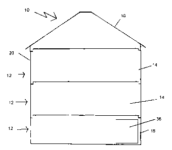
FIGURE 1 is a side elevation view, of a modular containment structure;
FIGURE 2 is a side elevation view, in section, of a modular containment
structure
illustrated in FIGURE 1;
FIGURE 3 is an exploded side elevation view of the modular containment
structure
Zo illustrated in FIGURE 1;
FIGURE 4 is a top plan view of a unitary peripheral sidewall member;
FIGURE 5 is a top plan view of a peripheral sidewall member fabricated in
sections
and secured together;
FIGURE 6 is a side elevation view, in section, of a modular containment
structure
15 illustrated in FIGURE 1, with a hopper;
FIGURE 7 is a side elevation view of the hopper illustrated in FIGURE 6.
DETAILED DESCRIPTION OF THE PREFERRED EMBODIMENT
The preferred embodiment, a modular containment structure generally identified
by
2 o reference numeral 10, will now be described with reference to FIGURES 1
through 7.
Structure and Relationship of Parts:
Referring to FIGURE 1, there is illustrated a modular containment system
generally reference by numeral 10. Referring to FIGURE 2, modular containment
25 system 10 includes a plurality of stackable building elements 12, which can
include two
or more peripheral sidewall members 14, a roof 16 and a base 18 which operates
as the
bottom. Referring to FIGURE 3, building elements 12 are stacked such that two

CA 02511355 2005-06-28
3
peripheral sidewall members 14 are stacked on top of base 18. Roof 16 is
stacked on top
of the top peripheral sidewall member 14 so as to form a storage container 20.
Referring to FIGURE 2, each peripheral sidewall member 14 has a top edge
profile 22 and a base edge profile 24. Top edge profile 22 is adapted to
engage with base
edge profile 24 of an adjoining peripheral side wall member 14. Roof 16 has a
base edge
profile 26 adapted to engage top edge profile 22 of adjoining peripheral
sidewall member
14. Base 18 has a top edge profile 28 adapted to engage base edge profile 24
of lowest
peripheral sidewall member 14. A seal 30 is provided between each of stackable
building
elements 12.
to In the illustrated embodiment, each of the stackable building elements 12
is
fabricated from concrete with reinforced with rebar to give the structure
strength so that
can hold grain, or heavier materials such as fertilizer, salt or sand. It will
be appreciated
that other materials than just concrete can also be used to fabricate building
elements 12 or
that one or more of the building elements 12 could also be fabricated from
materials other
than concrete or include other materials in addition to concrete in their
fabrication
Referring to FIGURE 2, roof 16 is provided with aeration apertures 32. Base 18
is
also provided with aeration apertures 34. Referring to FIGURE 1, peripheral
sidewall
members 14 can have closable openings 36 allowing for access to or from an
interior 38 of
container 20 illustrated in FIGURE 3.
Operation:
The use and operation of modular containment system generally identified by
reference numeral 10 will now be described with reference to FIGURES 1 through
7.
Referring to FIGURE 2, building elements 12 can be pre-fabricated out of
concrete.
Building elements 12 can be strengthened with rebar during the prefabrication
process.
Building elements 12 are then transferred to a site where containment system
10 is to be
erected. Referring to FIGURE 3, building members 12 are then stacked such that
one of
peripheral sidewall members 14 is stacked on top of base 18 which operates as
the bottom

CA 02511355 2005-06-28
4
or floor. Additional peripheral sidewall members 14 are then added as desired.
Finally,
roof 16 is stacked on top last peripheral sidewall members 14 so as to form
container 20.
During the stacking process, seals 30 are placed between building elements 12.
It will be
appreciated that while the building elements 12 are preferred to be made of
concrete, one
or more of the building elements 12 could also be fabricated from materials
other than
concrete or include other materials in addition to concrete in their
fabrication. Referring
to FIGURE 4, peripheral sidewalk can be of a unitary construction for ease of
fabrication. Referring to FIGURE 5, where peripheral sidewalk of a larger
circumference are required, such as those over 19 feet, peripheral sidewalk 14
can be
1o constructed in several sections and then assembled together. By way of
example, a first
halve 40 and a second halve 42 can be fabricated with flanges 44 on exterior
surface 46.
Flanges 44 are then aligned and coupling such as a pin 48 is inserted through
flanges 44 to
secure first halve 40 to second halve 42. It will be appreciated that other
methods of
securing first halve 40 and second halve 42 can be used. It will also be
appreciate that
1 s there could be more than two sections.
Referring to FIGURE l, when fabricated from concrete, storage container 20 is
less likely to tip in high winds due to the weight of the concrete even when
it is empty. It
is extremely durable yet inexpensive to fabricate. It can be transported and
assembled
easily. It can also be easily disassembled and transported to another site.
Storage
2o container 20 can be customized depending on the height desired. In the
illustrated
embodiment 10, only two peripheral sidewalk 14 are shown, however it will be
appreciated that more than two can be used to increase the height of storage
container 20.
In the illustrated embodiment, peripheral sidewalk 14 are circumferentially
round,
however the peripheral sidewalk could be prefabricated in other
circumferential shapes.
2s After being erected, storage container 20 can be use to store grain or
other
materials such as fertilizer, salt or sand. When necessary, storage container
20 can easily
be disassembled and move to another site. Even base 18 can be moved easily as
it is
prefabricated rather than being poured onsite.

CA 02511355 2005-06-28
Variations
Referring to FIGURE 6, storage container 20 can be fitted with a hopper 50
illustrated in FIGURE 7. Hopper 50 is particularly useful when storage
container 20 is
5 used to contain grain. Hopper 50 can also have an opening 52 for an aeration
system or
to provide access.
Cautionary Warnings:
In this patent document, the word "comprising" is used in its non-limiting
sense to
to mean that items following the word are included, but items not specifically
mentioned are not
excluded. A reference to an element by the indefinite article "a" does not
exclude the
possibility that more than one of the element is present, unless the context
clearly requires that
there be one and only one of the elements.
It will be apparent to one skilled in the art that modifications may be made
to the
illustrated embodiment without departing from the spirit and scope of the
invention as
hereinafter defined in the Claims.

Representative Drawing
A single figure which represents the drawing illustrating the invention.
Administrative Status

2024-08-01:As part of the Next Generation Patents (NGP) transition, the Canadian Patents Database (CPD) now contains a more detailed Event History, which replicates the Event Log of our new back-office solution.

Please note that "Inactive:" events refers to events no longer in use in our new back-office solution.

For a clearer understanding of the status of the application/patent presented on this page, the site Disclaimer , as well as the definitions for Patent , Event History , Maintenance Fee  and Payment History  should be consulted.

Event History

Description Date
Time Limit for Reversal Expired 2010-06-28
Application Not Reinstated by Deadline 2010-06-28
Deemed Abandoned - Failure to Respond to Maintenance Fee Notice 2009-06-29
Extension of Time to Top-up Small Entity Fees Requirements Determined Compliant 2008-01-21
Inactive: MF/reinstatement fee unallocated - Log 25 deleted 2008-01-21
Inactive: Acknowledgment of reinstatement not sent 2008-01-21
Letter Sent 2008-01-21
Inactive: Payment - Insufficient fee 2008-01-21
Reinstatement Requirements Deemed Compliant for All Abandonment Reasons 2007-12-24
Inactive: Office letter 2007-11-27
Small Entity Declaration Determined Compliant 2007-08-17
Inactive: Office letter 2007-07-20
Deemed Abandoned - Failure to Respond to Maintenance Fee Notice 2007-06-28
Application Published (Open to Public Inspection) 2006-12-28
Inactive: Cover page published 2006-12-27
Amendment Received - Voluntary Amendment 2006-06-28
Inactive: First IPC assigned 2005-11-02
Inactive: IPC assigned 2005-11-02
Inactive: IPC assigned 2005-11-01
Application Received - Regular National 2005-08-16
Filing Requirements Determined Compliant 2005-08-16
Inactive: Filing certificate - No RFE (English) 2005-08-16

Abandonment History

Abandonment Date Reason Reinstatement Date
2009-06-29
2007-06-28

Maintenance Fee

The last payment was received on 2008-06-30

Note : If the full payment has not been received on or before the date indicated, a further fee may be required which may be one of the following

  • the reinstatement fee;
  • the late payment fee; or
  • additional fee to reverse deemed expiry.

Please refer to the CIPO Patent Fees web page to see all current fee amounts.

Fee History

Fee Type Anniversary Year Due Date Paid Date
Application fee - small 2005-06-28
MF (application, 2nd anniv.) - standard 02 2007-06-28 2007-06-19
Reinstatement 2007-08-17
MF (application, 3rd anniv.) - small 03 2008-06-30 2008-06-30
Owners on Record

Note: Records showing the ownership history in alphabetical order.

Current Owners on Record
ANDREAS FROESE
ANATOLI FROESE
Past Owners on Record
None
Past Owners that do not appear in the "Owners on Record" listing will appear in other documentation within the application.
Documents

To view selected files, please enter reCAPTCHA code :


To view images, click a link in the Document Description column. To download the documents, select one or more checkboxes in the first column and then click the "Download Selected in PDF format (Zip Archive)" or the "Download Selected as Single PDF" button.

List of published and non-published patent-specific documents on the CPD .

If you have any difficulty accessing content, you can call the Client Service Centre at 1-866-997-1936 or send them an e-mail at CIPO Client Service Centre.


Document
Description 
Date
(yyyy-mm-dd) 
Number of pages   Size of Image (KB) 
Abstract 2005-06-28 1 11
Description 2005-06-28 5 179
Claims 2005-06-28 4 83
Drawings 2005-06-28 6 48
Representative drawing 2006-11-30 1 4
Cover Page 2006-12-13 1 29
Filing Certificate (English) 2005-08-16 1 157
Courtesy - Abandonment Letter (Maintenance Fee) 2007-08-23 1 174
Notice of Reinstatement 2008-01-21 1 166
Courtesy - Abandonment Letter (Maintenance Fee) 2009-08-24 1 174
Reminder - Request for Examination 2010-03-02 1 119
Correspondence 2005-08-16 1 33
Correspondence 2007-07-20 1 32
Fees 2007-06-19 1 31
Correspondence 2007-08-23 1 91
Correspondence 2007-08-17 1 63
Correspondence 2007-11-27 1 23
Fees 2007-08-17 1 33
Fees 2007-12-24 1 35
Fees 2008-06-30 1 27