Note: Descriptions are shown in the official language in which they were submitted.
CA 02511364 2005-06-20
WO 2004/060209 PCT/US2003/025930
MULTI-LUMEN VASCULAR GRAFTS HAVING
IMPROVED SELF-SEALING PROPERTIES
FIELD OF THE INVENTION
The present invention relates generally to an implantable prosthesis. More
particularly, the present invention relates to an implantable graft having an
integral multi
lumen structure.
BACKGROUND OF THE INVENTION
Implantable grafts are commonly used in treatment of diseased blood vessels.
One
such device is a synthetic vascular graft designed to replace damaged or
dysfunctional tissue.
Such damage or dysfunction can arise, for example, from arterial or venous
pathways that
have been damaged by thrombosis, an aneurysm or occlusion. The graft provides
an artificial
lumen through which blood may flow.
Natural blood vessels are often damaged during treatment of renal failure. For
example, when treating patients with renal failure using dialysis, it is
necessary to have ready
access to blood vessels in order to continuously withdraw blood from the
patient in amou~zts
of over 200 ml/min. For dialysis to be effective, it must be repeated on a
regular schedule of
two or more treatments per week. Each time, a vein is accessed using a
relatively large bore
needle. As a result of the repeated percutaneous access, the vein will often
collapse along the
puncture tract or become aneurismal, leaky, or filled with clot. The latter
can cause
significant risk of pulmonary embolism. As a result, in dialysis treatments,
artificial grafts
have been used as an alternative to using a patient's own veins, in an attempt
to avoid these
complications.
Thus, one increasingly useful application of a vascular prosthesis is as a
bypass shunt
between an artery and a vein. A graft surgically placed between an artery and
a vein
(AV fistula) is commonly used in dialysis patients. This bypass or fistula is
particularly
useful for allowing multiple needle access, as is required for hemodialysis
treatments.
Grafts can be made from a variety of materials such as textiles and formed
polymers.
Vascular grafts are often made from polytetrafluoroethylene (PTFE) tubes, and
in particular,
from expanded polytetrafluoroethylene (ePTFE) tubes. When PTFE is expanded or
stretched
CA 02511364 2005-06-20
WO 2004/060209 PCT/US2003/025930
to form tubes, the material consists of a unique microstructure of nodes
interconnected by
small fibrils. The space between the nodes that is spanned by the fibrils is
defined as the
internodal distance (IND). By varying the conditions of manufacture of the
ePTFE tubes,
such as temperature and rate of stretching and expansion, it is possible to
vary the space
between the nodes and the number and diameter of fibrils. Expanded PTFE is
particularly
suitable as an implantable prosthesis as it exhibits the desirable
characteristics of superior
biocompatibility and low thrombogenicity.
Expanded PTFE products that are stretched and expanded at high temperatures
and
rates are more homogeneous in structure. The IND is smaller and there are a
greater number
of fibrils in the ePTFE tubes. As a result, the product is stronger than if it
had been made at
lower temperatures and/or slower rates. In addition, the porosity is reduced.
By varying the
conditions of manufacture, it is possible to often obtain a final product
having desired
porosity, strength, and flex qualities.
It is a goal in graft technology to mimic, as closely as possible, the natural
function of
the blood vessel being replaced. This involves finding a graft material and
design that will be
sufficiently strong to resist tear and other mechanical damage, to be
sufficiently flexible and
compliant to accommodate the natural variability of flow and pressure of
blood, and to be
sufficiently porous to allow for enhanced healing and appropriate tissue
ingrowth to anchor
the prosthesis within the blood vessel and integrate it within the body.
The internal structure of ePTFE is desirable in a number of respects. The
diameter of
the fibrils formed in ePTFE is much smaller than the diameter of fibers of
lrnitted or woven
fabrics that have been used previously in vascular prostheses. Expanded PTFE
tubes having
a relatively large IND also possesses a higher degree of porosity than PTFE.
These
characteristics create a better substrate for cellular ingrowth, improved
flexibility, and greater
compliance in a graft. As a result, a prosthesis formed of ePTFE can more
closely
approximate the natural function of the blood vessel being replaced.
Consequently, reduced
thrombogenicity, reduced incidence of intima hyperplasia, and improved
cellular ingrowth
can be expected from ePTFE grafts as compared to a prosthesis formed of other
presently
available materials or unexpanded PTFE.
CA 02511364 2005-06-20
WO 2004/060209 PCT/US2003/025930
Current graft materials and designs have not fully achieved the desired result
of
mimicking natural vessels, and disadvantages of using the presently available
ePTFE grafts
remain. For example, when the IND is large so as to increase porosity and
improved
ingrowth, then the radial tensile strength of the tube is reduced as is the
ability of the tube to
retain sutures used during implantation. Such microporous tubes tend to
exhibit low axial
tear strength, so that a small tear or nick will tend to propagate along the
length of the tube.
Thus, there is a trade-off between optimal porosity and flexibility, and
optimal strength.
In addition to the usual structural limitations of using ePTFE for grafts,
there is an
additional disadvantage of using implantable ePTFE vascular grafts as access
shunts for
hemodialysis. Specifically, it is difficult to elicit natural occlusion of
suture holes created
during implantation. As a result, the PTFE grafts are generally not used to
withdraw blood
until they have been in place for a minimum of 14 days after surgery. This
time is required to
allow time for protective ingrowth tissue to form and keep blood from leafing
from the
suture holes. Use of the graft before this period may result in complications
such as a
hematoma surrounding the graft, false aneurysm, and possibly graft occlusion.
Thus, in order
to maintain the integrity of the graft, blood cannot be withdrawn from a PTFE
vascular graft
until the suture holes have healed. However, waiting this amount of time to
treat a dialysis
patient causes undesirable build-up of toxins in the blood with its attendant
problems.
A further problem associated with grafts used for hemodialysis is that
repeatedly
piercing the graft can compromise its integrity, causing large-scale tears in
some instances, or
more often result in hematomas where small amounts of blood leak from the
needle entry
point. A number of designs for ePTFE vascular grafts have been developed to
address these
problems.
For example, U.S. Patent No. 4,619,641 discloses a two-piece coaxial double
lumen
arteriovenous graft. This graft consists of an outer tube positioned over an
inner tube, the
space between being filled with a self sealing adhesive. The self sealing
adhesive helps
prevent hematomas caused by piercing the graft. A disadvantage of this design
is that
completely filling the space between tubes with adhesive limits its
flexibility and compliance.
CA 02511364 2005-06-20
WO 2004/060209 PCT/US2003/025930
In an attempt to increase radial tensile and axial tear strength of ePTFE
tubes, U.S.
Patent No. 4,743,480 discloses a method of altering the extrusion process so
as to reorient the
fibrils in the node and fibril matrix.
U.S. Patent No. 6,053,939 discloses a single layer ePTFE graft which releases
heparin
after grafting. Spaces between the nodes and fibrils are chemically treated to
malce the inner
surface of the tube hydrophilic. Tissue-inducing substances and anti-
thrombotic substances
(such as heparin) are then covalently bonded to the hydrophilic inner surface
of the tube and
pores. The result is a high patency ratio and reduced risk of thrombosis.
Although increased
patency is achieved using this technology, there is still a period of delay
before the graft can
safely be used for dialysis. In addition, there is still a risk of hematoma
caused by repeated
piercing of the graft during dialysis.
U.S. Patent No. 5,192,310 discloses a vascular graft having a primary lumen
and at
least one secondary lumen which share a common side wall. The secondary lumen
is filled
with a self sealing, non-biodegradable, biocompatible polymer. However, this
graft is
difficult to make using traditional extrusion methods. The graft is made by
using
unconventional methods, involving a combination extrusion and injection
molding process.
As a result, the manufacture of this graft is expected to result in a non-
uniform and irregular
pattern of nodes and fibrils. This irregular conformation becomes problematic
during the
sintering step during which time melt fractures and other inconsistencies in
the microstructure
will occur. Thus, this disclosed method of making the graft appears
unreliable, costly and
likely to produce a defective product.
Thus, there is a need for a graft which provides desirable porosity, resists
tears at suture holes, and resists blood flow through puncture holes caused by
repeated needle
access.
SUMMARY OF THE INVENTION
One advantage of the present invention is that there is provided a vascular
graft
having sufficient porosity, flexibility and strength to use in procedures
requiring repeated
needle access and which includes a self sealing capability.
CA 02511364 2005-06-20
WO 2004/060209 PCT/US2003/025930
Another advantage of the present invention is that the inventive vascular
grafts can be
used within a short period of time after implantation without adverse impact
to the integrity
of the graft.
A still further advantage of the present invention is that the inventive
grafts are easily
and reliably manufactured.
Another advantage of the present invention is that the inventive grafts
provide
superior assimilation capabilities and resealable properties.
It is a further advantage of the present invention that a self sealing graft
is provided
which performs a drug delivery function.
Briefly stated, the present invention provides an implantable graft, including
a
primary tubular body having a first outer wall surface and a first inner wall
surface defining a
primary blood contacting lumen; and a secondary tubular body having a second
outer wall
surface and a second inner wall surface. The secondary tubular body is located
about the
primary tubular body to form a space therebetween. The primary and secondary
tubular
bodies are joined by at least one rib.
The present invention further provides an implantable graft, including a
primary
tubular body formed of ePTFE having a first outer wall surface and a first
inner wall surface
defining a primary blood contacting lumen, a secondary tubular body formed of
ePTFE
having a second outer wall surface and a second inner wall surface, with the
secondary
tubular body being located about the primary tubular body to form a space
therebetween.
The primary and secondary tubular bodies are joined by at least one rib, the
rib defining a
plurality of secondary lumens. A self sealing polymeric material may be
located in at least
one of the secondary lumens.
The present invention also provides a method of forming a self sealing ePTFE
graft.
The method includes the steps of (1) pre-forming a PTFE structure from PTFE
paste into a
tubular shape having a primary lumen and at least one peripherally located non-
blood
contacting lumen, and (2) extruding the pre-formed PTFE structure through a
die having
spacing devices for holding open the non-blood contacting lumen to form a
multi-lumen tube.
CA 02511364 2005-06-20
WO 2004/060209 PCT/US2003/025930
Additionally, an implantable graft is provided, including a first tubular
blood
contacting member having a first inner wall surface and a first outer wall
surface and defining
a blood contacting lumen, a second tubular non-blood contacting member having
a second
inner wall surface and a second outer wall surface. The non-blood contacting
member is
arranged at least partially non-concentrically about the blood contacting
member so as to
define at least one non-blood contacting lumen therebetween. At least a
portion of the first
outer wall and the second inner wall are in contact and contiguous along a
length of the graft.
The members are laminated along said portion.
Further, the present invention also provides a method of forming a graft
including:
(1) extruding a first tubular member from PTFE paste having a first outer wall
surface and a
first inner wall surface defnung a primary blood contacting lumen; (2)
extruding a second
tubular member from PTFE paste having a second outer wall surface and a second
inner wall
surface; (3) arranging the second tubular member non-concentrically about the
first tubular
member along a length of the graft such that a portion of the first outer wall
contacts a portion
of the second inner wall; and (4) laminating the members to one another where
the members
are in contact.
The invention will be more fully appreciated by reference to the following
detailed
description in conjunction with the attached drawing in which like reference
numbers refer to
like elements throughout the several views.
BRIEF DESCRIPTION OF THE DRAWINGS
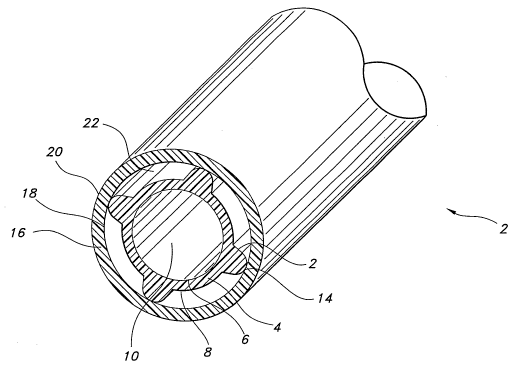
FIG. 1 is a perspective view of an implantable graft according to the present
invention.
FIG. 2 is a perspective view of an alternative embodiment of the present
invention.
FIG. 3 is a perspective view of a further embodiment of the present invention
including a tertiary lumen.
FIG. 4 is a perspective view of a further embodiment of the present invention
including: a self sealing elastomeric material, a plurality of drugs, and drug
delivery pores in
secondary lumens according to the present invention.
CA 02511364 2005-06-20
WO 2004/060209 PCT/US2003/025930
FIG. 5 is a perspective view of an embodiment of the present invention
including a
textile material around an exterior of the graft according to the present
invention.
FIG. 6 is a perspective view of a die used to form the graft as shown in FIG.
1.
DETAILED DESCRIPTION OF THE INVENTION
The prosthesis of the present invention includes an implantable self sealing
tubular
structure having a plurality of secondary lumens between a primary and a
secondary tubular
structure. Desirably, the prosthesis is formed from extruded PTFE or other
similar material
which exhibits superior biocompatibility.
In the present invention, a primary tubular body is formed which defines a
blood
contacting lumen. A secondary tubular structure is formed about and integral
with the first
tubular structure at an outer wall of the primary tubular body. A portion of
an inner wall of
the secondary tubular body and a portion of an outer wall of the primary
tubular body defines
at least one secondary lumen between the tubular bodies. The secondary lumen
may contain
a non-biodegradable self sealing elastomeric material. Optionally, a
pharmacologically or
physiologically active agent may be supplied in the graft for delivery to the
patient.
In an advantageous aspect of the invention, the device is a vascular graft
implanted
into the patient's arterial or venous system so that blood flow is established
through the
primary lumen.
Refernng now to FIG. 1, a multi-lumen graft of the present invention is
shovcm. The
graft, generally indicated by the numeral 2, is an elongate tubular structure
including a
primary tubular body 4 having an inner wall surface 6 and an outer wall
surface 8. The inner
wall surface 6 defines a blood contacting primary lumen 10. The primary
tubular body 4
includes a plurality of ribs 12 each having a radial apex 14. A secondary
tubular body 16
having an inner wall surface 18 and an outer wall surface 20 is arranged about
the primary
tubular body 4. The apexes 14 of the ribs 12 are in contact and integral with
that portion of
the inner wall surface 18 of the secondary tubular body 16 with which they are
in contact.
The outer wall 8 of the primary tubulax body 4 and the inner wall 18 of the
secondary tubular
body 16 between the ribs 12 define a plurality of secondary lumens 22. These
secondary
CA 02511364 2005-06-20
WO 2004/060209 PCT/US2003/025930
lumens 22 are non-blood contacting. There is no particular limitation to the
number of
secondary lumens 22.
Although FIG. 1 shows four secondary lumens, there are no particular
limitations to
the number of secondary lumens present in the graft. Similarly, there is no
particular
limitation as to the shape of the secondary lumens, although a narrow cross-
section is
preferred so as to maintain a cross-sectional size of the graft which
approximates, as closely
as possible, the natural vessel being replaced. The ribs may be thin to
separate the lumens or
may be relatively thick to serve a structural support function as well.
Relative thicknesses of
the material forming the primary and secondary tubular bodies may be varied
with respect to
one another. In addition, the size and shape of the ribs and the secondary
lumens may be the
same or different.
Referring now to FIG. 2, an alternative embodiment of the mufti-lumen graft
according to the invention is shown. As in the previous embodiment, the graft
2 is comprised ,
of a primary tubular body 4 having an inner wall surface 6 and an outer wall
surface 8. The
inner wall surface 6 defines a blood contacting primary lumen 10. A secondary
tubular body
16 having an inner wall surface 18 and an outer wall surface 20 is arranged
about the primary
tubular body 4. In this embodiment, the primaxy tubular body 4 is arranged at
least partially
non-concentrically within the secondary tubular body 16 so that a portion of
the outer wall
surface 8 of the primary tubular body 4 and a portion of the inner wall
surface 18 of the
secondary tubular body 16 are in contact and are made integral by use of, for
example, an
adhesive 46. The portion of these walls that are not in contact define a
secondary lumen 22.
hi this embodiment, there is a single secondary lumen 22 which is
substantially crescent-
shaped.
In a further aspect of the present invention, multiple layers of lumens
including
tertiary lumens are present on the graft. In this aspect, the graft may be
designed so that
access to the primary lumen is through at least one secondary lumen and one
tertiary lumen.
Referring now to FIG. 3, a further alternative embodiment of the mufti-lumen
graft
according to the invention is shown. The structure of the graft is as
described in the
embodiment shown in FIG. 1. In this embodiment, there are four secondary
lumens 22
arranged concentrically about the primary lumen 10. Additionally, a tertiary
tubular body 24
CA 02511364 2005-06-20
WO 2004/060209 PCT/US2003/025930
is provided including an inner wall surface 26 and an outer wall surface 28.
The tertiary
tubular body 24 is arranged about the secondary tubular body 16 in a partially
non-concentric
manner so that a portion of the inner wall surface 26 of the tertiary tubular
body 24 is in
contact and made integral with a portion of the outer wall surface 20 of the
secondary tubular
body 16 by an adhesive 46. The portion of these walls that are not in contact
define a tertiary
lumen 30. In this embodiment, the secondary lumens 22 are arranged
intermediate the
primary lumen 10 and the tertiary lumen 30.
In this particular aspect of the invention, the tertiary lumen, which is
closest to the
skin or access point, includes a self sealing material, while a secondary
lumen, which is
closer to the primary lumen through which blood flows, may include a self
sealing material
and/or a physiologically or pharmacologically active agent.
It is to be understood that the arrangement of contacting tubular bodies and
tubular
bodies connected by ribs may be used in any appropriate combination. Thus, the
tubular
bodies may be connected entirely by a ribbed connection, or entirely by non-
concentric wall
surface contact or any combination thereof.
In one advantageous aspect, the primary lumen is of a sufficient internal
diameter (ID)
to allow blood flow therethrough. This means that the ID of the primary lumen
will typically
be from about 3 mm to about 24 mm depending on the application.
The tubular structures of the present invention can be made from any suitable
biocompatible material that can be arranged to form a microporous structure.
Suitable
materials include polyimides, silicone, polyurethanes, polyurethane ethers,
polyurethane
esters, polyurethane areas, and mixtures and copolymers thereof. Desirable
materials include
polyethylene terephthalate (DacronTM brand polyester), and other synthetic
polyester fibers
such as mandrel spun polyurethane and silicone elastomeric fibers.
Particularly desirable
polymeric materials which are useful for this purpose include fluoropolymers,
for example,
either expanded or unexpanded polytetrafluoroethylene (PTFE). At least one of
the tubular
bodies is desirably made from PTFE, more desirably at least the primary
tubular body is
formed from ePTFE.
CA 02511364 2005-06-20
WO 2004/060209 PCT/US2003/025930
In one advantageous aspect of the invention, the materials forming the lumens
and
ribs of the graft possess an internodal distance of from about 1 ~,m to 200
pm. Even more
advantageously, the internodal distance is from about 10 ~.m to 100 pm.
In one advantageous aspect, the inventive graft is made using PTFE which
possesses
desirable porosity, radial tensile strength, and resistance to tears at suture
points.
Advantageously, at least the primary tubular body is formed of ePTFE having an
internodal
distance (IND) in excess of about 40 microns. Grafts having IND's in this
range generally
exhibit long-term patency as the larger pores promote formation of the intima
layer along the
inner blood contacting surface. Tubes having an lIVD less than about 40
microns exhibit
lesser healing characteristics, however offer superior radial tensile strength
and suture
retention strength, and are also within the scope of the invention.
The inner and outer tubular bodies of the present invention may be formed by a
variety of methods. For example, extrusion processes such as ram extrusion;
polymeric
casting techniques such as solvent casting and film casting; molding
techniques such as blow
molding, inj ection molding and rotational molding; and other thermoforming
techniques
useful with polymeric materials may be employed and chosen to best serve the
type of
material used and specific characteristics of the membrane desired.
One method for manufacturing porous PTFE tubing generally, is described,
for example, in U.S. Patent No. 3,953,566, U.S. Patent No. 3,962,153, and U.S.
Patent
No. 4,973,609, the entireties of which are herein incorporated by reference.
Generally, a
PTFE tube may be formed in four steps including preparation of a PTFE paste,
extrusion of a
tube, expansion of the tube, and sintering of the tube. Briefly, a PTFE paste
dispersion is
made for later extrusion by admixing a fine, virgin PTFE powder such as F-104,
F-103,
Virgin PTFE Fine Powder (Dakin America, Orangeburg, NY) with a liquid
lubricant such as
odorless mineral spirits or naphtha, i.e., Isopar~ (Exxon Chemical Co.,
Houston, TX), to
form a PTFE paste of the desired consistency. The PTFE paste is either passed
through a
tubular extrusion dye or coated onto a mandrel to form a tubular extrudate.
Next, the wet
extrudate is dried to evaporate the lubricant at either room temperature or
temperatures near
the lubricant's dry point. After the PTFE resin or paste is formed and dried,
it is stretched
and/or expanded. Stretching refers to elongation of formed resin while
expansion refers to
enlargement of the formed resin perpendicularly to its longitudinal axis. The
CA 02511364 2005-06-20
WO 2004/060209 PCT/US2003/025930
stretching/expansion step occurs at a temperature less than 327°C,
typically in the range of
250-326°C by an expansion rate of at least two to one (2:1). Finally,
the tubular extrudate is
sintered by heating it to a temperature of about 350-370°C. This
results in an amorphous
locking of the polymer.
The tubular bodies may be made integral at the rib apexes and wall surface
contact
points or the contacting wall surfaces in a variety of ways, depending on the
particular
materials which form the tubular bodies. Generally, as best shown in FIGS. 1-
4, the primary
and secondary tubular bodies 4 and 16 are laminated together at their points
of contact.
Numerous techniques may be employed to laminate or bond the primary tubular
body 4 to the
secondary tubular body 16. Heat setting, adhesive welding, application of
uniform force and
other bonding techniques known in the art may all be employed to bond or
secure the tubular
bodies 4 and 16 at their points of contact, be they rib 12 apexes 14 or
contacting wall surfaces
8 and 18. In each of these bonding techniques, it is contemplated that the
points of contact be
made integral.
Alternatively, it is possible to form the tubular bodies integrally during an
extrusion
process. In this case, desirably, the mandrel, dye and mold for the graft are
designed so as to
evenly distribute and form the PTFE paste into a desired shape and to produce
a graft having
a uniform node and fibril structure throughout the graft.
In one aspect of the invention, the tubular structures of the present
invention which
includes a rib or ribs may be formed of expanded PTFE by extrusion of a pre-
formed PTFE
structure having the shape of the final graft. Extrusion is performed using
dies having the
appropriate number of spacers to form the desired number of ribs. FIG. 6 is a
perspective
view of an exemplary die 44, corresponding to the illustrated graft of FIG. 1.
The die 44 may
be manufactured from materials available and well known in the art. A die mold
in the form
of a hollow cylinder (not shown) is placed around the die and the extrudate
forms the graft by
passing therethrough.
In grafts formed from ePTFE, the rate of stretching and the stretch ratio
affect the
porosity of the finished product in a predictable manner allowing a prosthetic
device to be
produced having a specified porosity. The rate of stretching refers to the
percentage of
elongation per second that the resin is stretched while the stretch ratio
refers to the
CA 02511364 2005-06-20
WO 2004/060209 PCT/US2003/025930
relationship between the final length of the stretched resin and the initial
length of the
stretched resin. For example, stretching an extruded PTFE tube at a stretch
ratio of two to one
and a stretch rate of sixty results in a porosity of approximately 40. This
porosity is a unit-
less number as determined in accord with the American Society For Testing of
Materials'
(ASTM's) Special Technical Publication Number 898. For example, based on
stretch ratios
ranging from two to one, to six to one, a stretch rate of sixty percent per
second yields a
porosity of between approximately 40 and approximately 90. A stretch rate of
one hundred
and forty percent per second at this ratio yields a porosity of between
approximately 60 and
approximately 85. Finally, a stretch rate of nine hundred percent per second
at this same ratio
yields a porosity of between approximately 65 and approximately 85.
In addition to the internodal distance and porosity, the geometry of the node
and fibril
network of PTFE can be controlled during stretching and expansion. In the case
of uniaxial
stretching, that is, elongation of the formed PTFE resin along the direction
of extrusion, the
nodes are elongated causing the longer axis of each node to be oriented
perpendicularly to the
direction of stretch. Accordingly, the fibrils are oriented parallel to the
direction of stretch.
Biaxial stretching additionally includes expanding the PTFE resin in the
radial direction and
can be utilized to produce a prosthetic device having a composite porosity. As
in uniaxial
stretching, the rate and ratio of radial expansion affects the resulting
porosity of the prosthetic
device.
In a particularly advantageous aspect of the invention, the geometry of the
node and
fibril network of ePTFE includes nodes oriented perpendicular to the direction
of stretch. In
a particularly preferred aspect, the nodes are uniformly oriented
perpendicular to the direction
of stretch.
In a further aspect of the present invention, one or more of the secondary
lumens
desirably include a non-biodegradable polymeric material which self compresses
after
puncture by a needle so as to seal the puncture site. This material serves a
self sealing
function in the graft of the present invention. Desirably, the self sealing
material is
biocompatible.
A number of different materials may serve as the self sealing polymeric
material
contemplated in the present invention. Some materials which may be used as a
self sealing
CA 02511364 2005-06-20
WO 2004/060209 PCT/US2003/025930
component in various forms include, but are not limited to, polymers and
copolymers,
including thermoplastic elastomers and certain silicones, silicone rubbers,
synthetic rubbers,
polyurethanes, polyethers, polyesters, polyamides and various fluoropolymers,
including, but
not limited to, PTFE, ePTFE, FEP (fluorinated ethylene propylene copolymer),
and PFA
(polyfluorinated alkanoate).
Furthermore, an exterior of the graft or a secondary lumen may be coated with
an
elastomeric material such as fluorine rubber, silicone rubber, urethane
rubber, acrylic rubber
or natural rubber to perform the self sealing function. Among the fluorine
rubber materials
are a vinylidene fluoride/hexafluoropropylene copolymer, a vinylidine
fluoride/chlorotrifluoroethylene copolymer, and a
tetrafluoroethylene/propylene copolymer.
Preferably, the self sealing polymeric material is crosslinked. For example, a
fluorine
rubber may be compounded with an acid acceptor, a crosslinking agent, and if
desired, a filler
before crosslinking. Examples of the acid acceptor are magnesium oxide and
calcium oxide. ;
Examples of the crosslinking agent are aliphatic polyamine derivatives,
organic peroxides,
and isocyanates. A typical compounding composition includes 100 parts by
weight of a
vinylidene fluoride/hexafluoropropylene copolymer, 15 parts of magnesium
oxide, and 0.5 to
3 parts by weight of an aliphatic polyamine derivative. Preferably, the
material is in a cross-
linked state so as to prevent deterioration in the body.
The self sealing material may be introduced into the graft by adhering in a
layer to at
least one surface of the primary and secondary tubular bodies. The adhesion
may take place
by mechanical means, chemical means (use of an adhesive), thermobonding or
combinations
thereof. Some polymers, particularly thermoplastic elastomers, become
sufficiently tacky
through heating to adhere to ePTFE tubular structures.
In use, the self sealing component may function by exerting a force in the
direction of
the puncture. If the self sealing material is adhered to both the primary and
secondary
tubular bodies, then either layer or both will seal the puncture site.
It is further within the purview of the present invention to include a
flowable
polymeric material as the self sealing material. The term flowable as used
herein refers to an
amorphous material which fills a void created by a deformation or puncture.
CA 02511364 2005-06-20
WO 2004/060209 PCT/US2003/025930
A number of different flowable polymer layers may also be employed in the
secondary and/or tertiary lumens to provide a self sealing graft. The flowable
polymer layer
seals the graft by possessing an amorphous quality which fills in any space
left open
subsequent to puncture of the graft. It may simply fill in the space left open
or it may
additionally penetrate into the punctured secondary lumen to fill any void
left from puncture
of a tubular body.
An example of a flowable polymer which may be used as the self sealing
polymeric
material in the present invention is an uncured or partially cured polymer.
The polymer may
be cured by a number of activating means which would activate curing
subsequent to
puncture of the graft, thereby sealing with the curing of the polymer.
Examples of materials
for such a flowable layer include, but are not limited to, uncured elastomers
such as natural or
synthetic rubbers, and natural gums such as gum arabic. Materials that are
particularly useful
in a flowable layer include non-crosslinked polyisobutylene which is also
known as uncured
butyl rubber.
Another flowable polymer layer which may be employed in the present invention
is a
gel. Gels are generally suspensions or emulsions of polymers which have
properties
intermediate between that of the liquid and solid states. A hydrogel may also
be used in the
present invention, and refers to polymeric material which swells in water
without dissolving,
and which retains a significant amount of water in its structure. The gels and
hydrogels
employed in the present invention may be biodegradable, or non-biodegradable.
They also
further may have polymeric beads suspended within the gel to effectuate
sealing of the graft.
Some examples of gels which may be used in the present invention include, but
are not
limited to, silicone gels, gum arabic, and low molecular weight ethylene/vinyl
acetate
polymers.
Suitable gels further include hydrogels formed from natural materials
including, but
not limited to, gelatin, collagen, albumin, casein, algin, carboxy methyl
cellulose, carageenan,
furcellaran, agarose, guar, locust bean gum, gum arabic, hydroxyethyl
cellulose,
hydroxypropyl cellulose, methyl cellulose, hydroxyallcylmethyl cellulose,
pectin, partially
deacetylated chitosan, starch and starch derivatives, including amylose and
amylopectin,
xanthan, polylysine, hyaluronic acid, and its derivatives, their salts, and
mixtures thereof.
CA 02511364 2005-06-20
WO 2004/060209 PCT/US2003/025930
In an advantageous aspect, a physiologically or pharmacologically active agent
may
be coated or otherwise incorporated into the graft according to the invention.
Any drug
or bio-therapeutic agent may be coated onto a surface or incorporated into a
lumen of the
graft of the present invention. Examples of suitable drugs or bio-therapeutic
agents may
include, without limitation, thrombo-resistant agents, antibiotic agents, anti-
tumor agents, cell
cycle regulating agents, their homologs, derivatives, fragments,
pharmaceutical salts, and
combinations thereof.
Useful thrombo-resistant agents may include, for example, heparin, heparin
sulfate,
hirudin, chondroitin sulfate, dermatan sulfate, keratin sulfate, lytic agents,
including
urokinase and streptokinase, their homologs, analogs, fragments, derivatives
and
pharmaceutical salts thereof.
Useful antibiotics may include, for example, penicillins, cephalosporins,
vancomycins, aminoglycosides, quinolones, polymyxins, erythromycins,
tetracyclines,
chloramphenicols, clindamycins, lincomycins, sulfonamides, their homologs,
analogs,
fragments, derivatives, pharmaceutical salts and mixtures thereof.
Useful anti-tumor agents may include, for example, paclitaxel, docetaxel,
alkylating
agents including mechlorethamine, chlorambucil, cyclophosphamide, melphalan
and
ifosfamide; antimetabolites including methotrexate, 6-mercaptopurine, 5-
fluorouracil and
cytarabine; plant alkaloids including vinblastine, vincristine and etoposide;
antibiotics
including doxorubicin, daunomycin, bleomycin, and mitomycin; nitrosureas
including
carmustine and lomustine; inorganic ions including cisplatin; biological
response modifiers
including interferon; enzymes including asparaginase; and hormones including
tamoxifen and
flutamide; their homologs, analogs, fragments, derivatives, pharmaceutical
salts and mixtures
thereof.
Useful anti-viral agents may include, for example, amantadines, rimantadines,
ribavirins, idoxuridines, vidarabines, trifluridines, acyclovirs,
ganciclovirs, zidovudines,
foscarnets, interferons, their homologs, analogs, fragments, derivatives,
pharmaceutical salts
and mixtures thereof
CA 02511364 2005-06-20
WO 2004/060209 PCT/US2003/025930
The agent may be provided in any of a variety of methods. For example, it is
possible
to form the graft with monomers including functional groups to which the
agents will bind.
The graft can be dip coated with a mixture of a drug in an appropriate buffer.
After allowing
the drug to react with the functional groups, the graft may be dried. See the
method as taught
in U.S. Patent No. 6,35,557, for example. Alternatively, it is also possible
to use the porous
nature of the graft material to hold therapeutic agents therein. The
therapeutic agent may be
added to the graft by addition of a therapeutic drug solution under pressure.
Furthermore, it
may be possible to add a therapeutic agent containing gel to one or more
secondary lumens
and to perforate portions of the wall surfaces of the tubular bodies to create
pores for
dispensing the gel slowly into the primary lumen or an exterior of the graft
over time.
Refernng now to FIG. 4, a mufti-lumen graft 2 according to the invention
includes a
self sealing polymeric material 32 in one of the secondary lumens 22. Another
of the
secondary lumens 22 includes a first drug 34 for treating a patient
intravenously. The graft
further includes secondary pores 38 arranged between a secondary lumen 22 and
the
secondary tubular body 16. A further drug 40 may be provided to a patient via
the secondary
pores 38. It is to be understood that, although the self sealing polymeric
material and the
drugs are in separate lumens, it is also possible for a single lumen to
contain one or more
drugs as well as the self sealing polymeric material. For example, it is
possible to coat a
surface of a secondary lumen adjacent the primaxy lumen surface with a
material containing
dissolvable time-released drug in a lumen filled with a self sealing gel. The
timed-release
drug may enter the bloodstream while the self sealing gel performs its
function. The timed
release of the drug does not necessarily rely on structural pores for drug
delivery. It is
possible for the drug to penetrate the intact surface of the secondary lumen.
In a further aspect of the invention, the graft may further include a support
member
such as a textile layer or sleeve on one or more of an exterior or an interior
of the graft. A
suitable textile for this purpose is a lazit biocompatible material such as
polyester or
polyethylene terephthalate (DACRON), for example. Referring now to FIG. 5, a
textile
sleeve 42 is shown covering the mufti-lumen graft 2. The textile sleeve 42
serves to provide
additional strength to the implant, and/or to aid in resisting tear from
suture holes.
The graft according to the present invention may be used advantageously, for
example, in implanting a self sealing graft device to replace or augment part
of an
CA 02511364 2005-06-20
WO 2004/060209 PCT/US2003/025930
arteriovenous (AV) pathway in an individual in need thereof. In the method, a
surgeon or
other qualified person surgically exposes the desired region for introduction
of the graft of the
invention. The desired site may be an area of occlusion or weakness in the
patient's
arteriovascular system, or the site for an AV bypass in a dialysis patient,
for example. An
interruption of the patient's blood flow is performed, and the device is
surgically implanted
and sutured or otherwise secured in place so that blood flow is established
through the
primary lumen. Once the graft is in place, the bloodstream can be accessed by
a cannula,
intravenous needle or the like through a secondary lumen. When the cannula or
needle is
withdrawn, the self sealing elastomeric material on the secondary lumen will
block access of
blood to the puncture hole created by the needle, thus preventing blood from
escaping from
the area of access.
The grafts of the present invention are particularly suited for use as AV
bypasses for
dialysis patients. The graft will be resistant to leaks at suture holes
because many of the
suture holes will be formed through the secondary lumens containing the self
sealing
material. This will allow use of the implant without having to wait extended
periods of time
to heal suture hole leaks. Further, even after repeated access to the device
by a large bore
needle, the implant will resist leakage of blood from the primary lumen.
Additionally, if a
drug delivery aspect is included in the graft, appropriate therapeutic drugs
will be available at
the site of injury to facilitate fast and reliable healing.
The invention may be embodied in other specific forms without departing from
the
spirit of essential characteristics thereof. The present embodiments are
therefore to be
considered in all respects as illustrative and not restrictive, the scope of
the invention being
indicated by the appended claims rather than by the foregoing description, and
all changes
which come within the meaning and range of equivalency of the claims are
therefore intended
to be embraced therein.