Language selection

Search

Patent 2511458 Summary

Third-party information liability

Some of the information on this Web page has been provided by external sources. The Government of Canada is not responsible for the accuracy, reliability or currency of the information supplied by external sources. Users wishing to rely upon this information should consult directly with the source of the information. Content provided by external sources is not subject to official languages, privacy and accessibility requirements.

Claims and Abstract availability

Any discrepancies in the text and image of the Claims and Abstract are due to differing posting times. Text of the Claims and Abstract are posted:

  • At the time the application is open to public inspection;
  • At the time of issue of the patent (grant).
(12) Patent: (11) CA 2511458
(54) English Title: FLEXIBLE TRAINING WHEEL ASSEMBLY
(54) French Title: ENSEMBLE ROUE D'APPRENTISSAGE FLEXIBLE
Status: Deemed expired
Bibliographic Data
(51) International Patent Classification (IPC):
  • B62H 7/00 (2006.01)
  • B62H 1/12 (2006.01)
(72) Inventors :
  • PICKERING, GRAHAM WILLIAM (Australia)
  • YEWDALL, GARY WAYNE (Australia)
(73) Owners :
  • PICKERING, GRAHAM WILLIAM (Australia)
  • YEWDALL, GARY WAYNE (Australia)
(71) Applicants :
  • PICKERING, GRAHAM WILLIAM (Australia)
  • YEWDALL, GARY WAYNE (Australia)
(74) Agent: BORDEN LADNER GERVAIS LLP
(74) Associate agent:
(45) Issued: 2011-08-02
(86) PCT Filing Date: 2003-12-23
(87) Open to Public Inspection: 2004-07-08
Examination requested: 2008-07-08
Availability of licence: N/A
(25) Language of filing: English

Patent Cooperation Treaty (PCT): Yes
(86) PCT Filing Number: PCT/AU2003/001721
(87) International Publication Number: WO2004/056644
(85) National Entry: 2005-06-22

(30) Application Priority Data:
Application No. Country/Territory Date
2002953539 Australia 2002-12-23

Abstracts

English Abstract


A flexible training wheel assembly fitted on each side of the rear wheel (10)
of a bicycle, each training wheel assembly comprising: an upper bracket (1)
removeably attached to the bicycle axle (11), a visco-elastic connector (2)
attached to the upper bracket (1), and a lower arm (3) attached to the visco-
elastic connector (2) at one end and to a training wheel (6) at the other end.


French Abstract

L'invention concerne un ensemble roue d'apprentissage flexible qui se fixe de chaque côté de la roue arrière (10) d'une bicyclette, chaque ensemble roue d'apprentissage comprenant : une patte de fixation supérieure (1) fixée de façon amovible à l'axe (11) de la roue arrière (10), un connecteur viscoélastique (2) fixé à la patte de fixation supérieure (1), ainsi qu'un bras inférieur (3) dont une extrémité est fixée au connecteur viscoélastique (2) et l'autre extrémité à une roue d'apprentissage (6).

Claims

Note: Claims are shown in the official language in which they were submitted.


CLAIMS:


1. A training wheel assembly to be fitted to a rear wheel of a bicycle for
providing lateral
dynamic stability of the bicycle, a pair of such training wheel assemblies to
be used
concurrently on opposite sides of a bicycle rear wheel, each of said training
wheel
assemblies comprising:
an auxiliary wheel;
a lower arm having an inboard end and an outboard end, the auxiliary wheel
being
pivotally attached to the lower arm outboard end;
a mounting bracket for removably attaching to the bicycle rear axle;
a visco-elastic polymer connector having an inboard surface attached to the
mounting
bracket and outboard surface attached in series to the inboard end of the
lower arm;
wherein the visco-elastic polymer connector of each of the pair of training
wheel
assemblies biases the rear wheel toward a vertical orientation and elastically
bends as the
rear wheel leans during a turning maneuver in response to the auxiliary wheel
contacting the
ground.

2. The training wheel assembly of claim 1, wherein the mounting bracket has a
slotted
hole found therein for vertical adjustment of the wheel assembly for
adjustment of the
amount of pre-load applied to the visco-elastic polymer connector, for the
weight and skill
level of a rider of the bicycle.

3. The training wheel assembly of claim 1, the visco-elastic polymer connector
having a
spring effect for progressively opposing the lean of the bicycle when a rider
leans the bicycle
when turning, for assisting the rider in maintaining balance.

4. The training wheel assembly of claim 1, the visco-elastic polymer connector
having
an inherent damping effect to absorb energy and dampen oscillation and
vibration of the
training wheel.

5. The training wheel assembly of claim 1, wherein the visco-elastic polymer
connector
has greater stiffness in the fore and aft direction for keeping the training
wheel substantially
parallel to the bicycle rear wheel during use.


6
6. The training wheel assembly of claim 5, wherein the visco-elastic polymer
connector
has two fasteners oriented side by side in a fore and aft direction.

7. The training wheel assembly of claim 5, wherein the visco-elastic polymer
connector
has a significantly greater dimension in the fore-aft direction than in the
lateral direction.

8. The training wheel assembly of claim 5, wherein the visco-elastic polymer
connector
has a significantly greater dimension in the fore-aft direction than in the
vertical direction.

Description

Note: Descriptions are shown in the official language in which they were submitted.


CA 02511458 2005-06-22
WO 2004/056644 PCT/AU2003/001721

FLEXIBLE TRAINING WHEEL ASSEMBLY
DESCRIPTION

FIELD OF THE INVENTION

The invention relates to the flexible training wheel assembly that is attached
to the rear wheel
of the bicycle to assist children to develop the balancing skill necessary to
ride a bicycle.
BACKGROUND OF THE INVENTION

Commercially available training wheel assemblies typically comprise rigid
brackets rigidly
attached to the bicycle rear wheel axle. This rigidity inhibits the learning
process. If the
wheels are set low, the bicycle cannot be leaned at all, either to make a turn
or just to
compensate for riding on a cambered surface. If the wheels are set high the
bicycle will lurch
from side to side in an unnerving manner and, once the rider is leaning on one
outrigger
wheel, there is no restorative force acting to encourage the rider to regain
the central
equilibrium position.

A number of patents have been registered showing various designs, which
attempt to address
this problem. Most of the configurations proposed incorporate a suspension
system based on
the concept of a pivoted bracket supported by a spring, with the various
fittings and fasteners
required to retain the spring, whilst permitting the desired range of
movement.

Some of these devices are quite complex and cumbersome, for example that
disclosed in U.S.
Pat. NO 4810000. In this design, the training wheels are raised and lowered by
cables attached
to the front wheel forks of the bicycle, which activates the cables as the
front wheel is turned.
As well as complexity and cost, this device has the added drawback that the
movement of the
training wheels is reliant upon correct adjustment of the mechanism, rather
than simply
responding to the normal lean of the rider.

Simpler, more viable designs typically employ a hinged bracket supported by a
compression
spring, plus the necessary fittings and fasteners. Typical of these devices
are those disclosed
in U.S. Pat N 's 5064213, 5100163 and 5352403.

These designs appear to be functional, however, since none appear to have been
commercialized their principal drawback would seem to be cost to manufacture;
they also
have a "gadgety" appearance, which may not appeal to the market.

More importantly, the exposed coil spring design presents numerous pinch-
points for trapping
and injuring small fingers, which is a significant drawback.

SUBSTITUTE SHEET (RULE 26) RO/AU


CA 02511458 2005-06-22
WO 2004/056644 PCT/AU2003/001721
2

The simplest design is that disclosed in U.S. Pat. No 6113122 and previously
in Pat. No
5707069. It's main feature is that it combines the structural support of the
outrigger wheel and
the flexible spring action desired in the one element, namely a helically
wound torsion spring.
This design appears to be functional and relatively cheap to manufacture.
However, it may
lack torsional rigidity about the vertical rod part of the member, allowing
excessive fore and aft
movement of the outrigger wheel. This would be especially so if the assemblies
were installed
back to front (ie. on the wrong sides), as the helical spring would then tend
to open, rather
than close.

The assemblies would need to be marked clearly "Left" and "Right" hand and
would need to
be installed correctly so. In addition, the steel torsion spring has virtually
no inherent damping
available to damp out unwanted oscillations or vibration.

SUMMARY OF THE INVENTION

It is an object of the present invention to provide a stabilizing device for
bicycles that also
allows the novice rider to develop a natural feel for the behaviour of a
bicycle, particularly over
uneven or sloping ground.

It is another object of the present invention to provide a stabilizing device
for bicycles that is
simple in construction and economical to manufacture.

It is another object of the present invention to provide a stabilizing device,
as described above,
that is easy to install and easy to adjust to reduce in effect, as the skill
of the rider increases.
The present invention has an upper bracket member and a lower arm member
flexibly joined
via a visco-elastic connector, which allows for angular movement between the
two members,
provides a spring force to progressively oppose the angular displacement and
has inherent
damping characteristics to damp out unwanted oscillations / vibration.

The upper bracket has a slotted hole near its upper end to allow the bracket
to be attached to
the rear wheel axle and for the position of the bracket to be adjusted
vertically. The geometry
of the assembly is such as to apply a pre-load to the flexible connector when
the bicycle
stands upright, under the weight of the rider. The amount of pre-load may be
adjusted to suit
the weight and / or skill level of the rider, by adjusting the height of the
upper bracket via the
slotted hole.

The upper bracket is also shaped to fit over an inner, lugged guide bracket,
which allows the
upper bracket to be adjusted vertically whilst maintaining its correct,
substantially vertical
orientation.

The training wheel is attached to the outer end of the lower arm, in a
conventional manner.
SUBSTITUTE SHEET (RULE 26) RO/AU


CA 02511458 2010-06-29

3
DRAWINGS

DESCRIPTION OF THE DRAWINGS
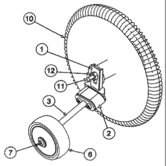
Figure 1

Fig. 1 is a perspective view showing the training wheel assembly fitted to the
rear wheel of a
small bicycle, in accordance with the present invention. The upper bracket (1)
is connected to
the bicycle rear wheel axle (11), secured by the wheel nut (12). The height of
the bracket is
adjusted to apply a pre-load the flexible connector (2), by. lowering the
bracket to the desired
degree beyond the point at which the wheel (6) first makes contact with the
ground. The
lower arm (3), the fastener (7) for the wheel, and bicycle rear wheel (10) are
depicted.
Figure 2

Fig. 2 is a rear view showing the training wheels (6) positioned to apply a
suitable pre-load to
the flexible connector (2). Without the weight of the rider, the bicycle rear
wheel will typically
be clear of the ground. Under the added weight of the rider, the flexible
connector(s) will
deflect and the bicycle rear wheel will make contact with the ground.

Figure 3

Fig. 3 is a rear view showing the training wheels linkages deflecting to
accommodate the
bicycle wheels leaning into a turn, on an uneven surface. In this way, the
rider is able to
develop a natural feel for the balance required to ride a bicycle whilst still
being supported by
the spring force in the flexible connector elements (2).

Figure 4

Fig. 4 is a perspective view showing the linkage assembly, with the wheel
omitted for clarity.
The upper bracket (1) is channel shaped in the upper portion, to allow it to
locate around the
guide bracket (5), yet move vertically for adjustment. The lower portion
slopes backward so
that its face makes an angle to the vertical (about 20 - 300) to achieve a
suitable geometry for
the linkage, depending upon the diameter of bicycle wheel and diameter of
training wheel in
question.

The visco-elastic connector (2) is bonded or fastened to the-lower face of the
upper bracket,
The visco-elastic connector has a dimension in the fore-aft (x) direction of
approximately twice
the dimension in the vertical (z) direction. The dimension in the lateral
direction (y) is selected
to be compatible with x & z dimensions. All dimensions and the type and
hardness of the
polymer compound are selected to give the desired spring rate. (Perhaps two
different
models may be required to cover the range of bicycle sizes and weights of
riders.)


CA 02511458 2010-06-29
4

The lower arm (3) is bonded or fastened to the visco-elastic connector (2), at
its upper face
plate. Fasteners (4) are depicted.
The lower end of this member has a tab bracket or similar provision for
accepting the wheel
fastener (bolt, typically). The face of this tab bracket is set at an angle to
the lower arm (about
700--900) to ensure that the alignment of the axis of the training wheel
matches the rest of the
geometry of the linkage assembly and that the training wheel is approximately
vertical under
typical pre-load conditions.

The lower arm is sized to carry the loads imposed upon it and to meet the
required geometry
of the linkage.

The guide bracket (5) is a conventional type, either solid or channel shaped,
with a hole
through the centre for the rear wheel axle to pass through. The guide bracket
also has a lug
on one side, sized to mate with the slot in the typical bicycle rear fork.

When this lug is correctly located in the slot, the guide bracket is prevented
from rotating,
ensuring that the training wheel assembly remains in the correct,
substantially vertical,
alignment. The design of the present invention is sufficiently robust that its
function is not
significantly affected by alignment variations normally encountered from
bicycle to bicycle.
The guide bracket is sized to fit neatly within the channel section of the
upper bracket (1).

Representative Drawing
A single figure which represents the drawing illustrating the invention.
Administrative Status

For a clearer understanding of the status of the application/patent presented on this page, the site Disclaimer , as well as the definitions for Patent , Administrative Status , Maintenance Fee  and Payment History  should be consulted.

Administrative Status

Title Date
Forecasted Issue Date 2011-08-02
(86) PCT Filing Date 2003-12-23
(87) PCT Publication Date 2004-07-08
(85) National Entry 2005-06-22
Examination Requested 2008-07-08
(45) Issued 2011-08-02
Deemed Expired 2019-12-23

Abandonment History

Abandonment Date Reason Reinstatement Date
2005-12-23 FAILURE TO PAY APPLICATION MAINTENANCE FEE 2006-01-13
2006-12-27 FAILURE TO PAY APPLICATION MAINTENANCE FEE 2007-01-24

Payment History

Fee Type Anniversary Year Due Date Amount Paid Paid Date
Application Fee $400.00 2005-06-22
Reinstatement: Failure to Pay Application Maintenance Fees $200.00 2006-01-13
Maintenance Fee - Application - New Act 2 2005-12-23 $100.00 2006-01-13
Reinstatement: Failure to Pay Application Maintenance Fees $200.00 2007-01-24
Maintenance Fee - Application - New Act 3 2006-12-27 $100.00 2007-01-24
Maintenance Fee - Application - New Act 4 2007-12-24 $100.00 2007-12-21
Request for Examination $800.00 2008-07-08
Maintenance Fee - Application - New Act 5 2008-12-23 $200.00 2008-12-23
Maintenance Fee - Application - New Act 6 2009-12-23 $200.00 2009-08-13
Maintenance Fee - Application - New Act 7 2010-12-23 $200.00 2010-12-23
Final Fee $300.00 2011-05-17
Maintenance Fee - Patent - New Act 8 2011-12-23 $200.00 2011-12-15
Maintenance Fee - Patent - New Act 9 2012-12-24 $200.00 2012-07-24
Maintenance Fee - Patent - New Act 10 2013-12-23 $250.00 2013-07-30
Maintenance Fee - Patent - New Act 11 2014-12-23 $250.00 2014-12-22
Maintenance Fee - Patent - New Act 12 2015-12-23 $250.00 2015-09-16
Maintenance Fee - Patent - New Act 13 2016-12-23 $250.00 2016-12-21
Maintenance Fee - Patent - New Act 14 2017-12-27 $250.00 2017-08-09
Maintenance Fee - Patent - New Act 15 2018-12-24 $450.00 2018-05-31
Owners on Record

Note: Records showing the ownership history in alphabetical order.

Current Owners on Record
PICKERING, GRAHAM WILLIAM
YEWDALL, GARY WAYNE
Past Owners on Record
None
Past Owners that do not appear in the "Owners on Record" listing will appear in other documentation within the application.
Documents

To view selected files, please enter reCAPTCHA code :


To view images, click a link in the Document Description column. To download the documents, select one or more checkboxes in the first column and then click the "Download Selected in PDF format (Zip Archive)" or the "Download Selected as Single PDF" button.

List of published and non-published patent-specific documents on the CPD .

If you have any difficulty accessing content, you can call the Client Service Centre at 1-866-997-1936 or send them an e-mail at CIPO Client Service Centre.


Document
Description 
Date
(yyyy-mm-dd) 
Number of pages   Size of Image (KB) 
Description 2010-06-29 4 197
Drawings 2010-06-29 4 71
Claims 2010-06-29 2 65
Abstract 2005-06-22 1 51
Claims 2005-06-22 1 35
Drawings 2005-06-22 4 69
Description 2005-06-22 4 188
Representative Drawing 2005-06-22 1 18
Cover Page 2005-09-19 1 39
Representative Drawing 2011-06-30 1 13
Cover Page 2011-06-30 1 41
Correspondence 2005-09-29 1 21
Correspondence 2008-08-07 2 30
Correspondence 2006-02-23 1 14
PCT 2005-06-22 4 130
Assignment 2005-06-22 1 32
Correspondence 2006-02-10 3 108
Correspondence 2008-08-18 1 17
Prosecution-Amendment 2008-07-08 1 27
Correspondence 2009-02-24 1 15
Prosecution-Amendment 2008-07-08 1 19
Prosecution-Amendment 2009-12-29 3 117
Prosecution-Amendment 2010-06-29 11 382
Correspondence 2011-05-17 1 31
Correspondence 2012-02-14 3 76
Assignment 2005-06-22 3 76