Note: Descriptions are shown in the official language in which they were submitted.
CA 02511488 2005-06-21
Doc. No. 107-5 CA/PCT Patent
LOCKING DEVICE
The invention relates to a locking device for a locking system. A locking
system here is
to be understood as a system with mechanical elements which permits or blocks
the access or
entry to an object, depending on whether an authorisation exists or not. A
locking device in
particular permits or prevents the actuation of a lock cylinder or lock by way
of turning a key or
a door knob, by way of actuating a door handle or comparable means, or in an
automated
manner, by way of suitable drive means etc.
Locking devices with mechanically and electronically - mechatronically -
controlled
blocking elements are known. They have all the properties of conventional,
purely mechanical
locking devices. The additional electronically controlled locking furthermore
permits the
possibility of activating and blocking keys individually. One may thus achieve
additional
flexibility in the lock organisation with mechatronic locking devices.
Electronically controlled locking is based on a data transmission between an
electronics
module on the key side, and an electronics module on the lock side. This data
transmission may
take place by way of contact - for example by way of electrical contact on the
key and lock - or
in a contact-free manner - for example by way of electromagnetic induction.
Data may be
transmitted in one direction only or in both directions. In the electronics
module on the lock side
or on the key side, on the basis of the transmitted data, it is checked as to
whether the inserted
key is authorised to access. If this is the case, then a motor on the lock
side is activated which
moves a blocking element in an electronically controlled manner, and in a
manner such that it
releases the lock cylinder or the lock.
Such a locking device is for example known from the international patent
application
publication WO 98/28508 or from the international patent application
publication WO
01/21913.
The disadvantages of such locking devices according to the state of the art is
the fact that
attempts at manipulation are sufficient to overcome the blocking of the lock
cylinder effected by
the b locking element. T his may be accomplished by w ay of the a ffect o f
shock, by w ay o f
vibrations or brute force or in any other manner.
In order despite this to guarantee a high security, such locking devices are
often
combined w ith a lements of a conventional, p urely mechanical locking d evice
w ith tumblers.
This for example is likewise known in the mentioned documents WO 98/28508 and
WO 01/21913. Such a combination entails a high operational reliability but it
limits the
CA 02511488 2005-06-21
Doc. No. 107-5 CA/PCT Patent
flexibility of a system operator for the following reasons: often the accesses
to an object (for
example to a building) which is most relevant to safety or most frequented are
provided with
mechatronical/mechanical locks. However yet further locks exists which are
designed in a
purely mechanical manner, for example doors to individual rooms in the inside
of the building.
These - on authorisation - are to be opened with the same key as with the
mechantronic/mechanical locks. If in an existing building locks are allocated
to a first lock
installation, then a combination with mechatronic/mechanical locks of a second
lock installation
- of the same manufacturer or another manufacturer - is not possible, which
for example is
disadvantageous if no mechatronic/mechanical closure system may be obtained
from the first
manufacturer. The same disadvantage exists if access solutions which are
comprehensive with
regard to the installation (which concern more than one installation) are to
be found.
Generally, with existing mechatronic systems, a happy medium is to be found
between
the contradicting demands of security and flexibility. Often, for retaining
the flexibility of
access, the mechanical permutation must be designed in a simultaneously
locking manner,
which of course is at the expense of the security.
Mechatronic locking devices with a drive-off element decoupled from a rotor
are shown
in the documents EP 1 030 O1 l, US 5,640,862, EP 0 312 123, FR 2 801 334 and
FR 2 552 809.
It would be desirable to have a locking device which is sufficiently secure in
order to
permit a decoupling from possibly present mechanical safety elements and
possible also permit a
functioning without additional safety measures by way of mechanical safety
elements.
It is therefore the object of the invention to provide a mechatronic locking
device which
is resistant to external foreign influences, in particular to the effects of
force, vibration or shock
or magnetic effects, and ensures a reliable and safe functioning.
The object is achieved by a locking device and the method as are defined by
the patent
claims.
The locking device comprises a coupling element and a drive-off element which
may be
brought into active connection with bolt means. I t may be brought into a
first and a second
coupling condition by way of electronically controlled drive means via advance
means which
move the coupling element. In the first coupling condition the rotor - thus
the part of the lock
which may be rotated by way of the key, door handle or similar means - is
decoupled from the
drive-off element in the context that no direct coupling via the coupling
element or other
coupling means i s p resent, w hich w ould h ave t he effect o f a rotation o
f the r otor c ausing a
2
CA 02511488 2005-06-21
Doc. No. 107-5 CA/PCT Patent
movement of the drive-off element. In its second coupling position, the
coupling element
couples the drive-off element to a rotor, which may be actuated by the key,
door handle, door
knob or a comparable means or by an electrical drive mechanism.
This idea is fundamentally different from existing ideas according to the
state of the art.
In the state of the art, a coupling between the rotor and a catch for
actuating the bolt is either
provided in a fixed manner or may be accomplished with the simplest of means,
for example by
way of inserting a key-like object. In the locked normal condition, the rotor
is locked with
respect to the housing, whereas a release of the rotor with respect to the
housing is effected with
the agreement of the mechanical coding and as the case may be, the electronic
coding. One must
therefore decouple the rotor and housing in order to manipulate the lock.
Accordingly, the idea according to the invention differs from the state of the
art in that
one does not simply need to decouple the rotor and housing but one must couple
the drive-off
1 S element to the rotor - and as the case may be - also must decouple it from
the housing. This
permits the coupling means - here the coupling element - to be selected in a
very simple manner
such that the coupling only comes into effect in a sole singular condition of
the coupling means.
This is advantageous for the following reason:
One may assume that with attempts at manipulation, the coupling element or
blocking
element may be deflected out of its rest position, for example by way of
knocks. This is
exploited with attempts at manipulation in that one manipulates with a
multitude of knocks until
the blocking element is located in the free position. The locking device is
simultaneously
influenced such that the blocking element once situated in the free position
is immediately fixed
in this - for example by way of a torque acting continually on the rotor.
The requirement of the coupling being accomplished only at a unique, singular
condition
reduces the probability of the coupling element getting into the second
coupling condition at all
by way of random agitations - knocks. And even if that were once to be the
case, the element
would be immediately removed from this position by way of the same random
agitation. Thus
only a very tiny time window is available in which one may perform any
manipulation. In
statistical mechanics, the number of all conditions which lead to the event
(successful
manipulation) is compared to the number of all possible conditions. If the
ratio is small, then the
event is improbable. In the terminology of statistical mechanics thus the idea
according to the
invention provides a very small phase space for attempts at manipulation.
Furthermore, it is not
possible to fix the coupling element onto the rotor by way of constantly
exerting a torque as
soon as it is in the second coupling position, since the rotor is not coupled
to the housing via the
3
CA 02511488 2005-06-21
Doc. No. 107-5 CA/PCT Patent
drive-off element but is freely rotatable or is fixed with another means which
is independent of
the coupling element.
By way of a driving-back force which has the effect that the coupling element
tends to
move away from the coupling position corresponding to the second coupling
condition, one may
even further reduce the probability of the coupling element coming into the
second coupling
position by chance.
The mechanical decoupling of the rotor and the drive-off element in the first
coupling
condition entails the advantage that the lock may also not be actuated by way
of a forced
rotation of the rotor. At the most the rotor rotates in an empty manner.
According to one embodiment, the drive-off element is blocked with respect to
a housing
in the first coupling condition. With this, it is additionally blocked from
rotation.
The coupling element may have an at least partly spherical surface and for
example be
formed as a ball. By way of this, the number of positions in which it couples
is minimised -
which is advantageous - as has been described above. There then exists the
requirement for the
shear lines between the elements to be coupled and the equator of the coupling
element to be
aligned to one another. If the equator of the coupling element is above or
below the shear line,
the coupling element is pushed away from the coupling position by way of
exerting force on one
of the elements to be coupled.
Preferably, the coupling element is neither coupled to the rotor nor to the
housing. The
coupling element then in its second coupling position, given a rotational
movement of the rotor,
may also be rotated with i t. F or t his, it 1 ies for example i n an o pening
which is formed b y
recesses in the rotor and in the drive-off element. A fixed mechanical
coupling to the drive-off
element a lso does not exist s uch a s f or example a hinge o r a p ositive f
it, b ut a t the m ost a
guiding by way of this recess in this drive-off element, i.e. even if the
coupling element may
always rotate with the drive-off element, it however is a mechanically
independent element. One
may envisage the rotor having to be brought back into its initial orientation
before the removal
of the key, thus may only be rotated by whole-number rotations.
The drive means may for example displace the coupling element between two
coupling
positions corresponding to the two coupling conditions. In the first coupling
position the
coupling element couples the housing and drive-off element whilst it effects
no coupling
between the rotor and drive-off element. In the second coupling position it
couples the rotor and
drive-off element, but effects no coupling between the housing and the drive-
off element.
4
CA 02511488 2005-06-21
Doc. No. 107-5 CA/PCT Patent
Alternatively to this an advance means of the drive means which serving as a
blocking
element may block the drive-off element with respect to the housing in a first
coupling
condition. In the second coupling condition the coupling element couples the
rotor and drive-off
element. A t the s ame time t he blocking element a nd t he coupling element
are d esigned a nd
arranged such that the blocking element when it is moved from the second to
the first coupling
condition, simultaneously by way of a direct or indirect affect moves the
coupling element away
from the coupling position.
A further alternative envisages the drive-off element not being blocked with
respect to
the housing also in the first coupling position. This is advantageous if the
drive-off element for
example is rigidly connected to an inner door handle. In this embodiment, on
the one hand it is
ensured that a person located in the inside of the object to be closed may
always leave the object.
On the other hand this direct coupling between the drive-off element and the
inner door handle
also represents a certain amount of protection from manipulation - the inner
door nevertheless
still always needs to be moved with it on each attempt at manipulation.
An electric motor with a travel spindle may be used as a drive means. Electric
motors are
relatively modest consumers of electricity in comparison the magnet actuators.
Furthermore they
are largely vibration-resistant, shock-resistant and magnet-resistant due to
their construction.
The coupling element may be displaceable by way of the drive means in a "quasi
forcibly guided" manner or even in a completely forcibly guided manner. This
means that the
position of the coupling element between the first and the second coupling
position is defined
every time by the drive means, for example in that they are connected to the
advance means of
the drive means. In the case of the quasi-forcible guiding, this connection
may only be released
by way of a certain force effort. It may for example be the case that the
advance means and/or
the coupling element comprises a permanent magnetic moment and the coupling
element clings
to the advance means on account of this. In the case of the forcible guiding,
the connection is so
firm t hat i t may n of b a r eleased at a 11 by way o f normal knocks. T he
coupling a lement f or
example is fixed on the advance m eans by w ay o f m echanical c onnections.
The mechanical
connections for example are released as soon as the coupling means are located
in the second
coupling position.
The locking device may thus be designed such that the coupling element is
always on
one of two predefined paths: on the first path quasi-forcibly guided or
forcibly guided between
the first and the second coupling position, on the second path rotated along
with the rotor and
relative to this in a constant position about an axis of the rotor.
5
' CA 02511488 2005-06-21
Doc. No. 107-5 CA/PCT Patent
The drive means may be provided with spring means which are formed and
arranged
such that the coupling element located between the first coupling position and
the second
coupling position may be moved against a spring force in the direction of the
first coupling
position by way of a mechanical action. With this one may prevent damage due
to forced
manipulation attempts and with the failure of the drive. If the coupling
element is located in an -
undefined - position between the first and the second coupling position and
force is exerted on a
shear line, then the coupling element backs away in the direction of the first
coupling position
without damage having arisen.
The locking device - for the case that it is used with a lock cylinder - may
comprise a
key-blocking element which may be moved from a first position into a second
position by way
of introducing the key into the key opening, wherein in the second position it
permits a
withdrawal of the key only at defined, predefined alignments of the rotor.
This on the one hand
permits the user to open a door in a manner known per se in that he pulls on
the key which is not
directed vertically. One the other hand it may be ensured that the system with
the key removed
is always in a defined position in which the coupling element is displaceable
between the two
coupling positions. One may also envisage the key-blocking element blocking
the rotor against
rotation in the first position so that this may not be moved away from its
defined position by way
of a screwdriver or similar means or by way of randomly induced movements.
With attempts to
move the rotor with a screwdriver or likewise and with much force, the key-
blocking element at
the most becomes damaged but due to the mechanical decoupling of the rotor and
the housing
this is never the case for the elements which are important for the actuation
of the bolt.
The key-blocking element - together with the coupling element - has the effect
that in
total three defined conditions are present:
1. No key is inserted: first coupling condition, and the key-blocking element
blocks the
rotor.
2 An unauthorised key is inserted: first coupling position, and the key-
blocking element
releases the rotor. The rotor is freely rotatable, but effects no actuation of
the bolt. The
key may only be pulled out in a defined position of the rotor.
3. The authorised key is inserted: second coupling condition, the rotor is
rotatable and its
rotation effects an actuation of the bolt.
The key-blocking element may for example be a toggle lever which is connected
to a
spring which effects a restoring force towards the first position.
6
CA 02511488 2005-06-21
Doc. No. 107-5 CA/PCT Patent
The additional security which is effected by the above mentioned elements has
the result
that the locking device makes do for example without purely mechanically
actuatable tumblers.
With this, a locking device according to the invention may be combined with
any type of
existing closure systems and may be applied in a manner which is comprehensive
with regard to
installations. The locking device permits a connection of several
installations and an application
in several installations with a system-neutral key.
The locking device according to the invention may however of course
additionally
further have mechanical tumblers.
The locking device according to the invention in this embodiment is thus
system-neutral:
mechanical and mechatronic system components may be completely separated.
In the following, preferred embodiments of the invention are described in more
detail by
way of the drawings. There are shown in:
Figure 1 schematically, a section through elements of a locking device
according to the
invention.
Figures 2 likewise schematically, a section through elements of a further
embodiment of a
locking device according to the invention.
Figure 3 schematically, the possible conditions for the coupling element in
the
arrangements according to Figures 1 and 2.
Figure 4 a view, partly in section, of elements of a cylinder lock with one
embodiment of
the locking device according to the invention, wherein the coupling element is
in
the first coupling position
Figure 5 the view according to claim 4, wherein a key is inserted into the key
opening and
the coupling element is located in the second coupling position.
Figure 6 an exploded representation of components of the drive means.
Figures 7
and 8 schematically, a section through a further embodiment in two coupling
conditions.
7
CA 02511488 2005-06-21
Doc. No. 107-5 CA/PCT Patent
Figures 9
and 10 a cross section and a longitudinal section (schematically) through a
lock with a
locking device according to the invention, in two coupling conditions.
Figure 11 a further cross section through the lock according to Figures 9 and
10.
A p rinciple forming the b asis o f one a mbodiment form of t he invention i s
s hown i n
Figure 1. A rotor 2 which may be rotated by way of a key and a stator 3, which
is connected to a
housing installed directly into a door and thus is not rotatable, are shown
very schematically. A
drive-off element 4 designed as a drive-off sleeve is located between the
rotor 2 and the stator 3.
This is at least partly rotatable about the rotational axis of the rotor and
may be brought into
active connection with a catch which is designed for actuating bolt elements
so that the bolt -
likewise, when certain conditions are fulfilled - may be actuated by way of
rotation of the drive-
off element 4. The rotor as well as the stator in each case have a recess 2.1,
3.1 which in the
shown arrangement are flush with a recess 4.1 in the drive-off element. A
coupling element 5 is
located in the opening which is formed by these recesses. In the figure the
coupling element is
formed as a ball 5. It may also have a different shape and for example be a
peg with a partly
spherical surface, or a pin. The manner of functioning is the following: the
coupling element
may be displaced in the opening by way of drive means which are not shown. It
assumes a first
coupling position or blocking position - when it is located on the shear line
S 1 which is formed
between the stator and the drive-off element. This condition corresponds to
the first coupling
condition. In its first coupling position, the coupling element couples the
drive-off element to the
stator. It prevents a rotation o f the drive-off element and thus an actuation
of t he b olt. The
coupling element however does not effect a coupling between the rotor and the
drive-off
element when it is in the first coupling position. The rotor and the drive-off
element and thus
also the rotor and the bolt are decoupled when the coupling element is located
in the blocking
position. This is in contrast to the state of the art where a blocking is
effected in that the rotor is
blocked with respect to the stator.
The coupling element 5 is in a second coupling position - or free position -
when it is on
the shear line S2 between the rotor and the drive-off element. This is the
second coupling
condition.
The arrangement shown in the figure is an example of a locking device with a
coupling
element 5 which in an electronically controlled manner may be displaced
between a first and a
second coupling position - corresponding to the first and the second coupling
condition, wherein
the coupling element 5, 5' in a first coupling position blocks the drive-off
element 4 with respect
8
CA 02511488 2005-06-21
Doc. No. 107-5 CA/PCT Patent
to the housing, and in a second coupling position couples the drive-off
element 4 to the rotor 2,
wherein the r otor 2 is not coupled to the d rive-off a lement 4 when the
coupling a lement i s
located in its first coupling position.
Figure 2 shows a variant of the principle shown in Figure 1 where the coupling
element
5' is not spherical but has a surface which is only partly spherical. The
recess 2.1 in the rotor in
this embodiment for example is limited such that the coupling element couples
the rotor 2 and
the drive-off element 4 only when it is introduced into the opening up to
abutment. If the
coupling element is retracted somewhat, then with a torque on the rotor, on
account of its partly
spherical surface it is pushed back in the direction of its first coupling
position.
Instead o f a h emispherical surface section o f F figure 2 one may also
provide another
surface shape which effects such rearward push, for example a spherical shape.
The actual
condition to be fulfilled in this embodiment is that the shape of the coupling
element is such that
it has a region in which it continuously tapers.
Of course the feature that the depth of the recess 2.1 in the rotor is limited
such that the
coupling element in its second coupling position is on an abutment or almost
on an abutment
may also be present with a spherical coupling element.
By way of Figure 3 it is now shown how the embodiments according to Figures 1
and 2
contribute to the probability for a successful opening of the lock being very
low and tending to
zero given manipulation attempts with random movements of the coupling
element.
Figure 3 very schematically represents the amount of all conditions 11. In the
arrangements of Figures 1 and 2, the coupling element is guided by the
mentioned recesses and
may only be displaced in a direction x. The conditions may also be
characterised by the position
in this direction x. The upper diagram of the figure shows the situation of
the arrangement
according to Figure 1. The sub quantity of those conditions in which the
coupling element is in
its second coupling position and the opening of the lock is rendered possible
is provided in the
figure with the reference numeral 12. Due to the spherical surface of the
coupling element, its
position must be selected in a very exact manner such that its equator is
located on the shear line
S2. Otherwise the coupling element given a torque acting on the rotor would
push away in the
one or the other direction. This fact has the effect that the sub-quantity 12
of conditions in which
a release is effected is very small. With random movements, the probability of
the coupling
element getting into the release position (the second coupling position)
rapidly disappears.
9
CA 02511488 2005-06-21
Doc. No. 107-5 CA/PCT Patent
The lower diagram of Figure 3 relates to the construction according to Figure
2. This
differs from t hat in F figure 1 i n t hat the coupling element in its second
c oupling p osition i s
simultaneously also on an abutment. The sub-quantity 12 of conditions in which
a release is
effected is therefore given right at the edge. In this case too it is small in
comparison to the
quantity of all conditions since the coupling element is likewise pushed away
from the coupling
position given a torque on the rotor, when it is not positioned exactly in the
coupling position.
Figure 3 thus explains how the described measures reduce the probability of
success of
manipulation attempts to a very low value already due to pure statistics.
Additional measures
may further reduce this success probability.
It is ensured that with agitations of the coupling element by way of knocks,
the speed of
the coupling element is always large when it is in that position which
corresponds to the
second coupling position. In the examples described here this is effected in
that the
coupling element in its first coupling position is fixed with a certain force -
it therefore
sticks quasi in the first coupling position. It may only be removed from this
at all by way
of a very massive knock, and with such, the speed of the releasing coupling
element is
very large. In the embodiment according to Figure 2 it is furthermore
immediately
reflected at the abutment and rushes back in the direction to the first
coupling position.
The sticking effect with which the coupling element is quasi fixed in the
first coupling
position may for example be effected by a ferro-magnet, but other means may
also be
used, for example a clamping or bonding or mechanisms similar to Velcro~
closures.
Further mechanisms are conceivable as for example the T-slots or swallow-tail
slots for
mechanical tumblers described in US patent 4 103 526.
2. A retreating force as is for example described in the already mentioned
publication WO
98/28508. This publication is referred to with regard to its effect. The s
ource of the
driving-back force may for example likewise be a ferromagnet.
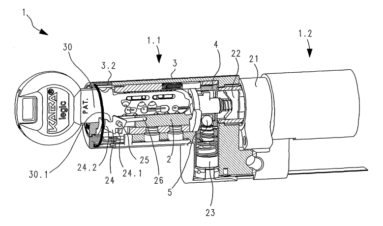
The cylinder lock which is partly shown in the Figures 4 a nd 5 has a double
lock
cylinder 1 with a first part cylinder 1.1 envisaged for a door outer side, and
a second part
cylinder 1.2 (optional) envisaged for a door inner side. The second part
cylinder 1.2 is shown in
the figure only in a schematic manner. The first part cylinder 1.1 has a rotor
2 and a stator 3
surrounding this rotor. The rotor is provided with a key opening 2.2. A catch
21 is likewise
shown which may be brought into connection with bar elements which are not
represented. The
catch 21 in a manner yet to be illustrated may be coupled to the drive-off
element 4 via a winged
element 22 which is to be inserted by way of introducing a key 30. An
analogous means may
also be provided for the possibly present second part cylinder 1.2. The winged
element 22 is
CA 02511488 2005-06-21
Doc. No. 107-5 CA/PCT Patent
mechanically coupled to a drive-off element 4. This may either be coupled to
housing parts or to
the stator 3 or to the rotor in a manner which has already been explained. The
coupling element
serving this purpose may be displaced by way of drive means 23 between the
first coupling
position (Figure 4) and the second coupling position (Figure 5). In the first
coupling position the
5 equator of the coupling element is located on the shear line between the
drive-off element and
the stator, in the second coupling position on the shear line between the
drive-off element and
rotor.
The drive means are electronically controlled. For the control, the cylinder
lock
comprises a non-represented electronics module and communication means for
communication
with a data Garner of the key 30. The communication means for the
communication between the
data Garner and the electronics module may be designed in a manner known per
se for a contact-
free communication via electromagnetic radiation, or the key may also comprise
contacts via
which contact pins of the cylinder lock may be contacted. Further
communication possibilities
are conceivable. The electronics module determines - for example likewise in a
manner known
per se - a nd b y w ay of data a xchanged w ith the data carrier o f t he k
ey, whether t he key is
authorised to access the object. With an authorisation, the electronics module
controls the drive
means such that these bring the coupling element into the second coupling
position and release
the lock (Figure 5). The owner of the key then with a rotation of the key may
effect a rotation of
the drive-off element 4, wherein the coupling element rotates along with it in
the opening which
is formed by recesses 2.1, 4.1 of the rotor and of the drive-off element. The
drive-off element 4
via a winged element 22 and catch 21 effects an actuation of bolt elements.
A key-blocking element 24 which may be moved between a first position (Figure
4) and
a s econd position (Figure 5 ) a nd i s designed as a t oggle lever is yet
shown n ear to the k ey
opening 2.2. This element is mounted on the rotor 2 by way of a rotation pin
25 and is held in its
first position with spring means 26 if no further forces act. In the first
position, by way of its
abutment on the stator 3 it blocks the rotor 2 from rotation in a standard
orientation. If a key is
inserted, it may be brought into its second position counter to the spring
force. The blocking of
the rotor is released by way of this and the rotor may rotate freely. As soon
as the rotor is no
longer in its standard orientation then by way of the abutment of a first
continuation 24.1 on an
end face 3.2 of the stator, the key-blocking element 24 is prevented from
being able to get back
into its first position. At the same time a second continuation 24.2 of the
key-blocking element
24 in cooperation with a projection 30.1 of the key 30 prevents the key from
being able to be
withdrawn.
Of course one may ensure in another manner that the coupling axis is
synchronised, for
example - in a manner known per se - by way of mechanical tumblers.
11
CA 02511488 2005-06-21
Doc. No. 107-5 CA/PCT Patent
The drive means 23 is yet described in further detail by way of Figure 6. It
comprises an
electric motor 40 by way of which a drive shaft 41 may be set into rotation. A
travel spindle 42
is placed onto this drive shaft 41 in a linearly displaceable manner along
this. An intermediate
part 43 present between the drive shaft 41 and the travel spindle 42 is
further drawn in the
drawing. A permanent magnet 45 is incorporated in the screw element. An
advance sleeve 47
with guide elements 48 which project through slots of the advance sleeve into
helical grooves of
the travel spindle 42 is mounted on the electric motor 40 with a spring 46.
The electric motor
with the travel spindle 42 and the advance sleeve 47 are surrounded and held
by a bearing sleeve
49. The spring 46 presses the advance sleeve 47 against an abutment surface
49.1 of the bearing
sleeve.
If the travel spindle 42 is set into rotation by the drive shaft, on account
of the guide
elements 48 projecting into the helical grooves, an advance (or retreat) onto
the travel spindle 42
is effected. The travel spindle may be displaced between a first retracted
position and a second
position in which for example it partly projects out of the bearing sleeve and
the advance sleeve
47. By way of this, the coupling element S in a guided manner is displaced
between its first and
second coupling position. If a force in the direction of its first coupling
position - thus
downwards in the figure - acts on the coupling element, then the coupling
element 5, the travel
spindle 42 and advance sleeve 47 on account of the effect of the spring 46
backs away
downwards against the spring force. As already mentioned, such a force may
arise on account of
a t orque a ding on t he rotor w hich t hen acts w hen t he coupling a lement
i s between the t wo
coupling positions.
An electricity supply cable 51 for the electronically controlled supply of the
electric
motor w ith a lectrical energy i s s hown i n t he figure, j ust a s a b ase p
late 501 eading t his a nd
possible electronic information transmission channels.
Of course the mechanism for exerting an advance described here is not the only
possible
manner in effecting an advance in an electronically controlled manner. The man
skilled in the art
would r ecognise many further p ossibilities o f how t o c onvert the r
otational movement of an
electric motor into an advance movement, for example by way of a screw gearing
in the present
case. Variants without an electric motor are conceivable, for example a
magnetic actuator.
Here the role of the permanent magnet 45 is to be briefly explained. If a
magnetised
body is in direct contact with ferromagnetic material, the ferromagnetic
domains are formed in
the ferromagnetic material such that the magnetic field runs in a continuous
manner in the
transition between the magnetised body and the ferromagnetic material. If a
short distance only
12
CA 02511488 2005-06-21
Doc. No. 107-5 CA/PCT Patent
separates the material and the body, such a continuous course is no longer
possible and one must
therefore consume energy in order to separate the material and the body. This
effects something
like a "sticking effect" which is known to everyone who has once played with
permanent
magnets. In the present case this effect is exploited in order to effect a
quasi-forcible guiding.
The coupling element 5 which for example contains nickel and/or cobalt may
only be detached
from the permanent magnet by way of massive knocks and once detached generally
has a high
speed. This "sticking effect" is reinforced even more if the coupling element
has a flat surface as
is drawn in Figure 2. A second effect is the remote effect: the permanent
magnet exerts a certain
attraction force onto the coupling element 5 by which means a driving-back
force arises whose
advantages have already been discussed above.
The permanent magnet also permits a cylinder installation position which is
rotated by
for example 180° in comparison to the shown embodiment.
The embodiment shown in Figures 7 and 8 differ from those in Figures 1-2 and 4-
5 in
that the coupling element in t he first coupling condition 1 ies in the inside
of the rotor. The
blocking of the drive-off element 4 with respect to the housing is effected by
a blocking element
which corresponds to an advance means 42 - for example a travel spindle 42 as
shown in Figure
6 - and in the first coupling condition is retracted into an opening in the
drive-off element. This
first coupling c ondition is s hown in Figure 8 . T he c oupling a lement 5 i
s located completely
within a peripheral line of the rotor 2. In the first coupling condition shown
in Figure 7, the
coupling element is placed such that its equator is located on the shear line
between the rotor and
the drive-off element 4 and thus couples the rotor and the drive-off element
(second coupling
position) The travel spindle 42 is retracted in this second coupling condition
so that the drive-off
element is rotatable. An inner and outer holding element 52 is also drawn
which have the effect
that the coupling element also remains in the second coupling position when
the rotor is rotated
and f or example t he gravity ( with a r otation about 1 80°) would
move t he coupling element
towards the inside of the rotor.
The manner of functioning of this embodiment is the following: in the first
coupling
condition ( Figure 8) t he travel s pindle 4 2 blocks the drive-off element 4
with respect to the
housing. The coupling element does not prevent a rotation of the rotor if no
other means (key-
blocking element or likewise) prevent a r otation of t he r otor. This t hen
may r otate in a free
manner but without any a ffect ( Fig. 8, 1 ower picture). A t ransition into t
he s econd coupling
condition for example is only possible if the system is in the aligned
orientation according to
Figure 8, upper picture, which again may be effected by a key-blocking
element. On transition,
the travel spindle is retracted in an electronically controlled manner, by
which means the
movement of the coupling element into the second coupling position is
effected, for example by
13
CA 02511488 2005-06-21
Doc. No. 107-5 CA/PCT Patent
way of gravity, a magnetic force as according to the previous examples and/or
a spring force
which acts on the outer of the holding elements 52 and is transmitted further
by this via the inner
holding element. In the second coupling condition the rotor is rotatable and
the drive-off element
is coupled to it; the bolt may be actuated. The outer holding element 52 is
located - for example
pressed-in initially by a spring force - within an outer peripheral line of
the drive-off element
and, when the drive-off element is rotated away, is held within this outer
peripheral line by way
of the housing or stator. By way of this, via the inner holding element 52, it
has the effect that
the coupling element 5 backs away to the inside.
The transition from the second into the first coupling condition is possible
only in the
aligned orientation drawn in the upper picture of Figure 7. The travel spindle
presses the
coupling element into the inside of the rotor and at the same time blocks the
drive-off element
with respect to the housing. The holding elements 52 are displaced outwards,
wherein in this
orientation a suitable recess is present for the outer holding element where
it for example is
pressed-in counter to the mentioned spring force.
In place of the drawn-in holding elements, other mechanisms are also
conceivable which
prevent the sliding of the coupling element into the inside of the rotor.
Although it has been shown in the Figures 4 and 5 how the locking device is
installed
into a cylinder lock, it is to be understood that the principle may also be
applied in other types of
locks. One example is drawn very schematically in Figure 9, 10 and 11.
Elements which have
already been described by way of Figures 1, 2, 4 and 5 have the same reference
numerals and
are not described here once again; the manner of action which has already been
explained is not
explained once again.
The rotor is connected directly to a door handle or to a similarly acting
means or to a
door knob for example in that a shank 61 of the door handle or of the door
knob is designed in a
rectangular manner and engages into a corresponding opening in the rotor. The
drive-off
element is o$en attached on an axis which in the installed condition lies over
an axis of a lock
cylinder and over the bolt means. Then suitable (not shown) coupling means are
present which
couple the drive-off element with bolt means which lie therebelow. On the
other hand the axis of
the door knob often corresponds to the axis of the lock cylinder replaced by
the door knob.
The locking device is drawn in the second coupling condition in Figure 9. The
coupling
element 5 projects into a recess in the rotor and by way of this couples the
rotor and the drive-off
element.
14
CA 02511488 2005-06-21
Doc. No. 107-5 CA/PCT Patent
The drive-off element 4 may be directly connected to a door handle on the
inner side or
means acting in a similar manner (only a rectangular shank 62 is shown). As
the case may be the
drive-off element in the first coupling condition is coupled to the housing 3
which leads to a
blocking of the door handle on the inner side. Alternatively a channel
(hollow) 3.3 in the shown
example is provided in the housing which forms a slotted piece and in w hich
the coupling
element 5 located in the first coupling condition together with the drive-off
element 4 may move
between two abutments without the rotor rotating as well (Fig. 10).
Alternatively to this, in the
first coupling condition the coupling element 5 may for example lie such that
it does not couple
the drive-off element with the housing in that it is retracted to such an
extent that it no longer
projects into the opening of the drive-off element. By way of this optional
coupling variant of
the drive-off element and the inner door handle with a simultaneous decoupling
from the
housing, one may ensure that a person located in the inside of the object to
be closed may leave
the object under all conditions. Furthermore the coupling of the inner door
handle to the drive-
off element likewise represents a certain obstacle with attempts at
manipulation.
In the shown embodiment the coupling element 5 is not designed spherically but
in a
peg-like manner. Here it is not magnetic as a whole but at its lower side
comprises an insert 5.1
of ferromagnetic material, for example of permanent-magnetic material. An
intermediate
element 65 of magnetic material, which here is spherical, is located between
the travel spindle
42 (or the permanent magnet 45) and the coupling element 5. The intermediate
element 65 has
the following functions: by way of its at least regional spherical surface and
the contact surfaces
which are only point-like due to this, it prevents rotational movements being
transmitted from
the travel spindle to the coupling element by which means frictional losses
would arise.
Furthermore in the shown embodiment the drive means may also be brought into
the second
coupling condition w hen t he drive-off a lement and the c oupling m eans a re
not in the initial
position, for example on account of a partial actuation of the inner door
handle or means acting
in a similar manner. This is represented in Fig. 10. With a return movement of
the drive-off
element and coupling means into the initial position or account of the action
of a spring, the
surfaces of the intermediate element 65 and coupling element S have the effect
that the coupling
element 5 is displaced upwards and engages into the recess 2.1 of the rotor,
thus directly into the
second coupling position.
The locking device according to the invention is particularly advantageous
with a direct
active connection between the door handle or the door knob and the rotor,
since particularly
large torques may be exerted by these means. The decoupling of the rotor 2 and
drive-off
element 4 according to the invention in the first coupling position here is
therefore particularly
advantageous.
CA 02511488 2005-06-21
Doc. No. 107-5 CA/PCT Patent
A section through the line XI-XI in Figure 9 is yet drawn in Figure 11. One
may
recognise a spring 66 for setting back the drive-off element (and as the case
may be of the inner
door handle or element acting in a similar manner) and an abutment element 67,
which is
designed as a simple insert part and permits a resetting between an operation
manner with a
rotation in the anti-clockwise direction and an operation manner with a
rotation in the clockwise
direction.
One may yet optionally provide a - possibly conventionally mechanically
functioning -
lock cylinder additionally to the locking device for the door handle or door
knob.
16