Note: Descriptions are shown in the official language in which they were submitted.
CA 02511930 2005-07-11
Method and Apparatus For Charging Batteries
FIELD OF THE INVENTION
The present invention relates generally to the art of battery charging.
More specifically, it relates to battery charging using versatile circuitry
that can
preferably receive multiple inputs and/or -provide multiple outputs.
BACKGROUND OF THE INVENTION
There are a large number of rechargeable batteries having a wide
variety of voltages and charging schedules, (Charging schedule, as used
herein, is the
manner in which the charging is performed for a given battery. For example,
one
charging schedule might call for a limited amount of current initially, and
then a
greater current when the battery voltage crosses a threshold, followed by a
trickle
charge after the battery voltage crosses alsecond threshold.) It is typical
that a
charger be designed for a single battery type, and have a single output
voltage and
charging schedule. Of course, dedicated'battery chargers are not versatile,
and can
require a facility to have a number of chargers.
Other chargers are not dedicated, but are "dumb" chargers that apply a
~
constant voltage output with the charging current being controlled by the
load, not the
charger. These chargers might work for any battery of a given voltage, but do
not
optimally charge batteries. Thus, if such. chargers are used to charge several
batteries
simultaneously, they cannot provide a unique charging current or voltage for
each
battery. Rather, a single charging schedule is used for all batteries being
charged.
This also diminishes the usefulness of chargers.
CA 02511930 2005-07-11
-2-
Some battery chargers are, inefficient because they have a poor power
factor. This causes increased costs when power is utility power, and can
lessen the
charging capacity, particularly when using generator power. The use of
generator
power can cause another problem - generators often provide "dirty" power, i.
e. ,
power that is not perfectly sinusoidal, or not of a constant value. Dirty
power can
result in improper charging.
Prior art battery chargers are often design for a single input voltage and
frequency. While this might be sufficient for consumer battery chargers, some
applications, such as industrial battery charging, or automotive charging,
might be
used at different locations where the input power is not the same.
Rechargeable batteries have a finite life, in that their ability to be
charged diminishes over time. Often, a user finds the battery is no longer
chargeable
by charging it, then using it, and having the battery become discharged in a
short
period of time.
Accordingly, a battery charger that is versatile enough to charge
different types of batteries, or to simultaneously charge batteries with
different
outputs, is desirable. A modular design,: where output circuits for particular
batteries
can beswitched in and out by the user, is 'one manner to allow different
charging
schedules. Also, a single output module could be used for any battery type,
where
the user selects the battery type, or the charger senses the battery type.
Preferably,
such a charger will provide power factor correction, and be able to receive a
wide
range of inputs. Also, it will preferably be able to receive dirty power, and
still
charge a battery. A charger that provides the user a warning when a battery is
defective is also desirable.
SUMMARY OF THE PRESENT INVENTION
According to a first aspect of the invention a battery charger and method
of charging a battery include using an input rectif er to receive an ac input
and provide a
dc signal. A converter receives the dc signal and provides a converter output.
An
output circuit receives the converter output and provides a battery charging
signal. A
controller controls the converter to power factor correct.
According to a second aspect of the invention a battery charging system
and method includes an input circuit that receives an input signal and
provides a dc
signal. A plurality of user-removable output circuits are designed to receive
the dc
CA 02511930 2005-07-11
-3-
signal and provide a battery charging signal at a desired voltage and a
desired current,
and only one of the output cirMits is connected at a time. A controller,
controls the
connected output circuit.
According to a third aspect of the invention a battery charging system
and method includes an input circuit that receives an input signal and
provides a dc
signal. A plurality of output circuits are connected at the same time, and
receive the dc
signal and provide a battery charging signal at a desired voltage or voltages
and a
desired current or currents. A controller provides a control signal to each of
the output
circuits.
The converter output has a magnitude independent of a range of
frequencies and a range of magnitudes of the ac input in one alternative.
The converter output has a substantially constant magnitude for a range
of inputs spanning at least a factor of two or at least two utility voltages
in various
embodiments.
The controller includes a charging schedule module. The charging
schedule modules receives voltage feedback and/or current feedback. The output
circuit
is a dc-dc converter controlled in response to the feedback in other
embodiments.
The controller includes a battery selection input, and controls the charger
in response to the battery selection inpiit. The selection input is responsive
to a user-
selection, or a wired or wireless battery type sensor, such as an RFID sensor,
in various
embodiments.
The output circuit is designed for a particular battery voltage and the
output circuit may be removable in another embodiment.
Additional output circuits,.for the same or different voltages, and for use
one at a time, or a plurality at a time, and user removable or fixed, are
provided in
various embodiments.
The conveiter may be a boost converter, a buck-boost converter, and a
combined rectifier boost converter in various alternatives.
The output circuit may be a switched converter, a pulse width modulated
inverter, a pulse width modulated forward converter, or a frequency modulated
in other
embodiments.
A defective battery sensor module receives current, voltage or
temperature feedback and determines if a battery is defective is provided in
another
CA 02511930 2005-07-11
. . i
-4-
embodiment. A user-noticeable indicator.is provided when a defective battery
is
detected.
Power for the controller is derived independent of the input in another
embodiment.
Other principal features and advantages of the invention will become
apparent to those skilled in the art upon review of the following drawings,
the detailed
description and the appended claims.
BRIEF DESCRIPTION OF THE DRAWINGS
Figure 1 is a block diagram-of a battery charger in accordance with the
preferred embodiment;
Figure 2 is a circuit diagraxn of a preregulator in accordance with the
preferred embodiment;
Figure 3 is a circuit diagram of an alternative preregulator in
accordance with the preferred embodiment;.
Figure 4 is a circuit' diagram of an alternative preregulator in
accordance with the preferred embodiment;
Figure 5 is a circuit diagram of an output circuit in accordance with -the
preferred embodiment;
Figure 6 is a circuit diagram of an output circuit in accordance with the
preferred embodiment;
Before explaining at least one embodiment of the invention in detail it
is to be understood that the. invention is not limited in its application to
the details of
construction and the arrangement of the components set forth in the following
description or illustrated in the drawings.: The invention is capable of other
embodiments or of being practiced or carried out in various ways. Also, it is
to be
understood that the phraseology and terminology employed herein is for the
purpose
of description and should not be regardedas limiting. Like reference numerals
are
used to indicate like components.
DETAILED DESCRIPTION OF THE PREFERRED EMBODIMENTS
While the present invention will be illustrated with reference to a
particular battery charger and particular circuitry, it should be understood
at the
CA 02511930 2007-06-26
outset ttiat the invention may also be implemented with other circuit-i y,
software and
arrangements.
Generally, the invention is implemented by a battery charger that
receives an input, such as an ac input, and provides a de charging output.
Preferably,
the battery charger may receive any input over a range of inputs without being
reconfigured (i.e., re-linked or re-wired), and may be capable of receiving
"dirty"
power, such as that from a generator. Also, the battery charger preferably
includes
an output stage that can either provide a number of voltages for charging
different
batteries, any voltage, or be designed for a. single voltage. There can be a
plurality of
user-removable output stages. When the output circuits provides a single
voltage, or
a narrow range of voltages for charging. one battery voltage, it is said to be
designed
for a particular battery voltage. In one embodiment a number of output stages
are
provided, each for charging one batteryy wherein the batteries are of the same
type or
of different types.
When the output circuit is capable charging different battery types, the
user can set the battery type or voltage, or the charger can include a sensor.
The
sensor could be wired (i.e., connected to the battery and either sense an ID
signal, or
sense the voltage of the battery), or wireless, such as an RFID* sensor to
sense an RFID tag on a battery. The charger preferably includes a controller
that causes the output to follow a charging schedule based on the battery type
and/or voltage.
Another feature the charger preferably has is a "bad" battery detector,
wherein the controller senses that a battery is not properly charging. The
user is
notified of the bad or defective battery. Another alternative provides a
polarity
detector to prevent damage to the batteryand/or charger if the battery is
connected
with the wrong polarity.
The power provided for battery charging is not always ideal utility
power, but might be "dirty" generator power. The present invention can provide
a
battery charger that is capable of running off a generator source (as well as
a utility
source). A capacitor or other energy storage device delivers energy to a dc
bus in
such a way as to reduce the impact of dirty power on the charging circuit and
allows
for charging during heavy loading of the generator source.
One advantage of the preferred embodiment is that it will operate using
a wide range of input powers, and thus is well-suited for applications or
users that use
the charger in multiple locations. Various embodiments provide for an input
range of
'~ Radio Frequency Identification
CA 02511930 2005-07-11
-6-
at least a factor of 2, at least two utility voltages (115-230V, or 100-256V
e.g.), 120V
to 525V, or 100V to 633V. The preferred embodiment is relatively lightweight,
adding to the charger's portability. Additionally, the power circuit does not
need to
be re-linked or reconfigured by the user for different powers, thus there is
less of a
need to open the housing.
The details of the preferred embodiment will be provided below, but
they generally include a rectifier, followed by a boost converter or a buck-
boost
converter, followed by a dc-dc converter, such as a pulse width or frequency
modulated inverter or forward converter. A controller controls the boost
converter to
provide a dc bus having a desired magnitude, regardless of the magnitude and
frequency of the input (within ranges), and to actively power factor correct
the input.
The controller also controls the dc-dc converter using feedback of the battery
charging
signal. Battery charging signal, as used herein, includes the signal used to
charge the
battery. For example, the charging current is controlled using a current
feedback
loop. A voltage feedback loop may be. used to stop the charging process, or to
change
to a trickle charging mode. Controller 110 may use functions of the current
and/or
voltage feedback and/or temperature feedback, such as power, energy, and
integrals
and derivatives of the output parameters. `While the feedback signals -are
typically
indicative of a magnitude, the controller may be responsive to the signal by
using a
function of the value fedback.
When using the features described above, a versatile charger may be
made that is capable of receiving a wide range of inputs, and charging a wide
range of
batteries, having a number of voltages. For example, multiple output stages
may be
provided and each run off the commori bus. Each output stage may be controlled
independently of the others, to charge either the same type of batteries, or
different
batteries, either one at a time, or a plurality at a time.
Referring now to Figure 1; a block diagram of a preferred embodiment
of a charging system 100 is shown. Charger 100 includes a preregulator 102, a
plurality of output circuits 104, 106, and 108, a controller 110, and feedback
lines/control inputs 112-120 that cooperate to charge batteries 105, 107 and
109.
While the embodiment illustrated includes three output circuits, other
embodiments
include fewer (including just one) output circuit, or many more output
circuits. In
various embodiments output circuits 104, 106 and 108 are fixed in place, or
user
interchangeable or user-removable. Controller 110 may be located on a single
board
CA 02511930 2005-07-11
-7-
or dispersed among several boards. It may be particularly useful to disperse
controller 110 among several boards, one in a housing with the preregulator,
and one
with each output circuit, when the output circuits are user-removable.
User-removable, as used herein, includes a portion of the system being
housed in such a way as the user can remove it and replace it with relative
ease. For
example, batteries on cordless power tools are user-removable, as are
batteries in
automobiles. Depending upon the application and sophistication of the user,
more or
less effort by the user is required to remove. the output circuit.
The preferred embodiment provides that preregulator 102 includes a
full or half-bridge rectifier (input circuit) and a boost or buck-boost
circuit. Examples
of such circuits are shown in Figures 2 and 3. Their operation is well known,
and
won't be described herein but a boost circuit can increase an input voltage to
a desired
magnitude, and a buck-boost circuit can increase or decrease an input voltage
to a
desired magnitude. In various embodiments the rectifier is omitted (for dc
inputs,
e.g.), or combined with the boost circuit; such as shown in Figure 4. Combined
rectifier-boost, as used herein, includes a circuit such as Figure 4, where
the rectifier
is part of the boost circuit.
Preregulator,102 receives an ac input and provides a dc bus. AC input,
as used herein, includes any utility, generator, or other ac signal. The input
can be of
a different type, such as dc, in other embodiments. If a dc input is used, a
rectifier is
not needed. The signal that causes the switch in the boost or buck-boost
converter to
change states is received on a control input (an input for control rather than
power
signals). The operation of the preregulator results in a de bus that is has a
magnitude
independent of the input magnitude, and is dc, independent of the input
frequency.
Thus, the input signal may have any frequency and magnitude within a range of
magnitudes and a range of frequencies, and preregulator 102 will still provide
the
desired dc bus.
Alternative embodiments include other preregulator switched
converters, such as a buck, SEPIC, or CUK converter. Converter, as used
herein,
includes a power circuit that receives or provides an ac or dc signal, and
converts it to
the other of an ac or dc signal, or to a different frequency or magnitude.
Controller 110 preferably controls the preregulator to be power factor
corrected to improve efficiency. The power factor correction is active, in
that the
controller switches the boost switch 203 to increase the power factor. The
power
CA 02511930 2005-07-11
-8-
factor correction may be accomplished using a power factor correction circuit
204
(located in controller 110), such as an off the shelf integrated circuit that
provides
power factor correction for boost circuits.
The output of ttie preregulator is a dc bus at a voltage controlled by
controller 110. The preferred embodiment provides that the converter output (a
dc
bus) be controlled to have a voltage of 950V regardless of the input voltage
or
frequency. Other bus voltages may be used.
Controller, as used herein, includes digital and analog circuitry,
discrete or integrated circuitry, microprocessors, DSPs, etc., and software,
hardware
and firmware, located on one or more boards, used to control a device such as
a
preregulator, power circuit, or output circuit. Controller 110 receives power
from a
controller power source which may be a separate transformer based source,
battery,
or the dc bus.
The dc bus is maintained at a substantially constant voltage (there may
be ripple voltage or other voltage perturbations that do not adversely impact
performance) by capacitors 206 (which may be implemented with one or more
capacitors). The invention contemplates that "dirty" power might be used to
charge
batteries. Thus, the capacitance is selected to overcome the problems caused
by dirty
power.
Over time, the energy provided by the generator source must be greater
than the energy used to charge the batteries. However, for lengths of time on
the
order of the period of the input power the charging energy maybe greater than
the
generator-provided energy. DC bus capacitors 206 have a capacitance, according
to
the present invention, sufficient to provide the difference between needed
output
power when and the available generator power. In the preferred embodiment, dc
bus
capacitor 206 can store an amount of energy equal to the energy (over time)
available
in approximately 2.75 cycles of the input signal, or in other words, an amount
of
energy equal to approximately E=2.75(P)(T) joules, where P is the maximum
output
of the charger (combined for all output circuits) and T is the period of the
generator
ac signal. This overcomes the transients that occur in the input power which
are
typically on the order of a cycle T in length. In alternative embodiments of
the
present invention, capacitor 206 can store an amount of energy at least equal
to the
energy (over time) available in at least 1.5 cycles of the input signal (or in
other
CA 02511930 2005-07-11
_9_
words, E=1.5(P)(T)), in at least 2 cycles of the input signal (E=2(P)(T)), or
in at
least 2.5 cycles of the input signal (E=2.5(P)(T)).
Thus, the capacitance of capacitor 206 is C =5.5(P) (T)/(V 2), where V is
the bus voltage for E=2.75(P)(T), or energy for 2.75 cycles, and C=3(P)(T)/(V
2),
where for 1.5 cycles, and C=4(P)(T)/(V2), for 2 cycles and C=5(P)(T)/(V2) for
2.5
cycles.
In the preferred embodiment, the approximate values of P, T, and V
are: P=1250 watts, T=16.67 milliseconds (or 20 msec for 50 Hz), and V =950
volts.
This results in a capacitance value for capacitor 206 of at least 127
microfarads in the
preferred embodiment, and capacitance values of at least 70 microfarads, at
least 92
microfarads, and at least 115 microfarads, for the various equations for C
described
above.
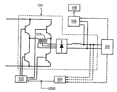
Referring now to Figures 5 and 6, example of preferred output circuits
104 and 106 are shown. The embodiment shown in Figure 5 is a pulse-width
modulated inverter, and the embodiment of Figure 6 is a forward converter. The
general operation of both circuits is well known. Other embodiments
contemplate
frequency modulation and/or other output. converters, particularly converters
that
switch a signal applied to a transformer primary, and provide the output
through the
transformer secondary, thereby isolating the input and output.
The embodiment of Figure 5 includes an inverter that, for example,
inverts the 950v bus through the primary of transformer 505. The secondary of
center-tapped transformer 505 is rectified and the dc signal is provided to
charge the
battery. Controller 110 modulates the pulse widths to provide a desired
output.
Various embodiments include full or half bridge topologies, or other
topologies. The
signal used to pulse width or frequency modulate or otherwise control the load
current
and/or voltage may be called a load control signal. The preferred output
circuits are
easily controlled to provide any output voltage. Thus, they may be used for
any type
of battery within a range, so long as the battery is identified (by the user
or sensed,
e.g.), and a charging schedule is availablefor that battery. Also, the
preferred output
circuits may be dedicated to a single battery voltage and/or type, for example
by
including control circuitry with the output circuit.
In one embodiment, a portion of controller 110 is included in the
housing that houses output circuit 104, and monitors the output current to
provide a
desired charging current, in accordance with a charging schedule provided by a
CA 02511930 2005-07-11
. . ~
-10-
charging schedule module 502 ( which is part of controller 110). Module, as
used
herein, includes software and/or hardware that cooperates to perform one or
more
tasks, and can include digital commands; control circuitry, power circuitry,
networking hardware, etc. A charging schedule module is a module that provides
a
charging schedule.
Charging schedule module 502 includes a current module responsive to
current feedback and a voltage module responsive to voltage feedback in the
preferred
embodiment. The current feedback may be considered part of an inner control
loop.
Voltage feedback is used in an outer control loop, to determine when the
battery is
nearly charged, and when the battery voltage crosses a threshold, the charging
current
is greatly reduced to a trickle charge. Other embodiments provide for
monitoring the
battery temperature, and reducing charging current based on temperature. The
charging schedule can include any needed, feature, such as an initial slow
charge, a
discharge mode, atriclde charge, etc. Integrated circuits that provide a
charging
schedule are commercially available.
The housing containing output circuit 104 may also include a battery
sensor 504, which is part of controller 1.10. and senses battery 105, and
provides a
signal indicative of the battery -type andlor, voltage to charging schedule
module 502.
Battery sensor 504 may be wired or wirelessly connected to battery 105. A
wired
connection allows battery sensor 504 to determine the battery voltage and/or
type
from the battery terminals, or from a separate terminal on the battery which
provides
information of voltage and/or type. Battery sensor, as used herein, is a
sensor that
determines battery type and/or voltage. The battery sensor can be part of
controller
110, or part of the output circuit.
A wireless connection is made when the battery has a wireless
transmitter which transmits information of the battery type and voltage. One
such
wireless system is an RFID (radio-frequency identification) system. An RFID
tag
which transmits information is placed on the battery, and sensor 504 includes
an
RFID receiver which receives the information. The information transmitted and
received can be similar to "bar code" information, or it can be more or less
complex.
Sensor 504 is an optical bar code reader, a.-WIFI receiver, a magnetic strip
reader or
other wireless reader various embodiments. Controller 110 includes a battery
selection input that receives the information from the sensor. Battery
selection input,
as used herein, includes any input that receives information, sensed or
provided by
CA 02511930 2005-07-11
. , ~
the user, of battery voltage and/or type. The charging schedule module is
responsive
to battery selection input, in that the charging schedule is chosen or
modified based on
the battery type.
The battery type and/or voltage is provided on a user-selectable input,
such as a panel knob, button or selector, or by instructions sent on by pda,
computer,
wireless controller, etc. in various embodiments to the battery selection
input on
controller 110. User-selectable input, as used herein, includes any input sent
from the
user, either locally or remotely.
According to various embodiments each output circuit is designed for a
particular battery type and/or voltage. The output circuits may be permanently
fixed
or user removable. Thus to charge a 12 volt automotive battery the user
selects the
12 volt output circuit, or automotive battery output circuit, and connects it
to the
preregulator. Similarly, to charge a 24 volt battery, the user connects the 24
volt
output circuit to the preregulator. Preferably, the connection involves
snapping a
housing into place, wherein an electrical connection and a structural
connection is
made. For example, a portable power tool battery is connected to the tool to
make
both an electrical and a structural connection.
The invention contemplates' multiple output circuits connected to a
preregulator at one time, as shown in Figure 1. In such an embodiment, each
output
circuit includes its own control circuitry (that is part of controller 110) to
provide the
required output (which can be sensed, set, or fixed as described above). Each
output
circuit receives the dc bus and inverts or converts it to its particular
desired output.
The various output circuits may be identical or different and may provide the
same or
different outputs.
As described above, charging current and voltage (and battery
temperature in some embodiments) is provided to controller 110. That
information,
or other battery characteristics, is used, in various embodiments, to
determine
whether a battery is defective (cannot be properly charged), either because it
has
reached the end of its recharging life or perhaps because of a manufacturing
defect or
it has been damaged. Temperature can be directly monitored or remotely sensed,
such as by an infrared sensor, for example:
Controller 110 includes a defective battery sensor module 506 detects a
defective battery by comparing the a battery characteristic such as current
and/or
voltage and/or temperature to a known profile. If the characteristic deviates
beyond a
CA 02511930 2005-07-11
-12-
threshold, controller 110 determines the battery is defective. For example,
some
charging schedules provide for trickle charging batteries having a voltage
below a
threshold. If the trickle charging fails to raise the voltage above a
threshold, that
battery is deemed defective. The components and or software used to detect the
inability to properly charge are referred to as a defective battery sensor
module.
When controller 110 determines a battery is defective it activates a
user-noticeable output 508 such as a warning light, audible alarm, an instant
message
sent remotely or an email message. The warning can be sent by a wired
connection
or a wireless connection. User-noticeable output, as used herein, includes a
warning
indicator on a housing (such as on the housing for the output circuit or the
preregulator), or a message sent to a telephone, pda, computer, remote
indicator, etc.
Numerous modif =ications -may be made to the present invention which
still fall within the intended scope hereof. Thus, it should be apparent that
there has
been provided in accordance with the present invention a method and apparatus
for
battery charging that fully satisfies the objectives and advantages set forth
above.
Although the invention has been described i-n conjunction with specific
embodiments
thereof, it is evident that many alternadves, modifications and variations
will be
apparent to -those skilled in the art. Accordingly, it is intended to embrace
all such
alternatives, modifications and variations. that fall within the spirit and
broad scope of
the appended claims.