Note: Descriptions are shown in the official language in which they were submitted.
' ~ CA 02512105 2005-06-29
1
Method for making a thermally protective coating for a
propulsive unit structure
Background of the invention
The present invention relates to a method of making
an internal and/or external thermally-protective coating
for a thruster structure, in particular a structure
forming part of a solid-propellant thruster. The
invention also relates to a method of making a thruster
structure, and to the thruster structure obtained
thereby.
The structure of a solid propellant thruster
essentially comprises a casing, e.g. made of composite
material and generally provided with an internal
thermally-protective coating that needs to perform three
essential functions: providing the composite casing with
thermal protection against attack from the hot gas that
results from combustion of the propellant; attenuating
the mechanical stresses generated by the casing deforming
under pressure during combustion of the propellant; and
sealing the casing against gas leaks.
Various methods exist for applying thermally-
protective coatings to the inside of the casing of a
thruster structure. One of them consists in starting by
using means that are conventional in the rubber industry
(open mills, kneaders, ...) to prepare a rubber of
viscous consistency in the semi-manufactured non-
vulcanized state, and in transforming the rubber into
elastomer sheets for cutting out and then draping on a
mandrel prior to performing vulcanization in an
autoclave. The various thermal protection elements
formed in that way are then disassembled from their
respective mandrels in order to be assembled on another
mandrel (generally a dismountable mandrel made of metal)
used for winding the filaments of the composite casing
onto the thermal protection prepared in that way. That
method leads to long manufacturing cycles which cause
CA 02512105 2005-06-29
2
that technology to be particularly expensive to
implement. It requires a large amount of tooling and
also presents a succession of operations that are
discontinuous and some of which are manual. The use of a
plurality of different mandrels during the various steps
in implementation of the method is also time-consuming
and lengthens the duration of the manufacturing cycle.
Another type of known method enables implementation
costs to be reduced. It consists in covering a mandrel
in a layer of elastomer prior to forming the casing of
the thruster structure by winding the filament of a
composite material. In such a method, the elastomer
layer is made by depositing an extruded strip over the
entire outside surface of a rotating mandrel. The
coating obtained in that way is then vulcanized in an
autoclave prior to winding on the filament. Although
such a method simplifies the method of making the
internal thermally-protective coating, it still requires
complex tooling to be used such as an extruder, and
therefore still presents implementation costs that are
high. In particular, it is necessary to vulcanize the
coating in order to give it the desired mechanical and
thermal characteristics. The operation of vulcanization
in an autoclave takes place under the combined effects of
pressure (generally of the order of 1 megapascal (MPa) to
3 MPa), and of temperature (typically of the order of
140°C to 180°C). As a result, it is necessary for the
mandrel to be mechanically dimensioned relative to the
autoclave pressure, which leads to mandrel designs that
are much more complex than would be necessary when using
a mandrel specific for the operation of winding the
filament of the structure.
Furthermore, flexible thermally-protective coatings
make use of rubbers (a specific association of
ingredients) that are specially formulated to perform the
three above-specified main functions, i.e. withstanding
ablation in the face of thermal and mechanical attack
' ' CA 02512105 2005-06-29
3
from the propergol combustion gas, providing thermal
insulation for the structure, and attenuating mechanical
stresses. In addition, given that optimizing the
performance of a solid propellant thruster requires its
dead weight to be reduced (i.e. including the weight of
its internal thermal protection), the ideal material for
forming this internal thermal protection needs to present
very good resistance to ablation by the thermal
mechanical attack from the combustion gas, associated
with low density, and low thermal conductivity.
Unfortunately, the formulation techniques for obtaining
good resistance to ablation and the formulation
techniques for obtaining low density (which is generally
associated with low thermal conductivity) are mutually ,
antagonistic, so that when only one material is used for
performing the thermal protection function, it is
necessary to find a compromise in terms of thermal
characteristics and ablation characteristics. Finding
such a compromise generally leads to a solution that is
not good for thruster performance. To mitigate that
drawback, it is possible to envisage thermal protection
solutions that include function gradients. Such
solutions consist in using a material having good
resistance to ablation, generally associated with high
density, for those layers of the coating that are
directly exposed to the combustion gas, while using a
material of low density, generally associated with low
thermal conductivity, for the underlying layers that are
not exposed throughout the time the thruster is in
operation. However such solutions are very rarely
applied because they lead to additional manufacturing
costs, both in terms of preparing the rubber in a non-
vulcanized semi-manufactured state, and in terms of
actually fabricating the thermal protection elements.
Object and summary of the invention
The present invention thus seeks to mitigate such
CA 02512105 2005-06-29
4
drawbacks by proposing a method of making a thermally-
protective coating for a thruster structure that
considerably reduces implementation operations, thereby
simplifying the necessary tooling and manufacturing
cycles. The method of the invention makes it possible to
obtain a coating by optimally satisfying the functions
associated with a thermally-protective coating of a
thruster structure. The invention also seeks to propose
a method that is equally suitable for making internal
thermal protection and external thermal protection for a
thruster structure. The invention also seeks to provide
a thruster structure fitted with an internal and/or
external thermally-protective coating as obtained by the
method, and the invention also relates to a thruster
structure as made in this way.
To this end, the invention provides a method of
making a thermally-protective coating for a thruster
structure, the method being characterized in that it
consists in: continuously measuring out and mixing at
least one polyurethane and a mixture of polymerization
agents in which specific fillers have previously been
dispersed; coating a rotating cylindrical support surface
by continuously casting a strip of touching turns of the
resulting mixture; and pre-polymerizing the resulting
coating at ambient pressure so that said polyurethane
becomes polymerized sufficiently to be capable of being
stressed mechanically.
As a result, compared with the methods described
above, it is possible significantly to shorten
manufacturing cycles for the thermally-protective
coating, and thus reduce the cost of making it. The
various steps of the method of the invention can be
performed on a single, multifunction workstation, and can
follow one another continuously without interruption
concerning the mixing and casting steps, and can be
automated almost entirely.
CA 02512105 2005-06-29
The mixture for coating the support surface
comprises in particular a pre-polymer type polyurethane.
Preferably, it has isocyanate terminal groups and is
advantageously the result of reacting a polyether with
5 diphenyl-methane-diisocyanate. The polymerizing agents
are advantageously of the amine type and/or of the polyol
type. In addition, it is preferable to select powder
and/or fiber fillers. The powder fillers may be of the
silica type and/or an antimony trioxide and/or chlorine-
containing compounds, and/or glass microbeads, and/or
silica microbeads, and/or acrylonitrile microbeads.
Fiber fillers may comprise fibers that are discontinuous,
and of the aramid type and/or of the cellulose type.
Such a mixture is remarkable in that in spite of the
high filler content needed for performing the thermal
protection function, it is in a substantially liquid
state on leaving the casting head, it gels quickly so as
to avoid flowing away from the support surface while it
is being deposited thereon, and after polymerizing at
ambient pressure it changes to a state in which it is
partially, but sufficiently, polymerized to allow the
coating to be subjected to mechanical stress.
By continuously and automatically varying the
parameters of the method (such as the concentrations of
the various polymerization agents, the casting rate, the
speed of rotation of the support surface, the travel
speed of the casing head), it is possible to deposit
varying thicknesses over surfaces that may be cylindrical
or spherical. In addition, when making a thick
thermally-protective coating, it is also possible to
deposit the coating in a plurality of successive passes,
while still maintaining the continuous and automatic
nature of the method.
The quantities of polyurethane and of the
polymerization agents can be caused to vary so as to
obtain both a first mixture and at least one second
mixture. Under such circumstances, while maintaining the
' ~ CA 02512105 2005-06-29
6
continuous and automatic nature of the method, it is
possible to make a coating on the support surface by
covering a casting of a strip of a first mixture, e.g.
having good resistance to ablation by the combustion gas,
with a casting of a strip of a second mixture, e.g.
having low density and low thermal conductivity.
The method may also include a step of machining the
pre-polymerized coating to take up a desired external
profile. A final step may also be provided consisting in
polymerizing the pre-polymerized coating by hot curing.
The method of making a thruster structure of the
invention consists in providing a casing with an internal
coating and/or an external coating for providing thermal
protection that is made by the method described above.
Such a method may be applied to making a thruster
structure in which the support surface used for making an
internal thermally-protective coating is an outside
surface of a rotating mandrel. The casing of the
thruster is then deposited and bonded to an outside
surface of the coating as made in this way. When the
casing of the thruster is obtained by winding a filament
of a composite material, the winding of the composite
material is preferably polymerized simultaneously with
polymerizing the coating by hot curing. The thruster
structure obtained in this way is then separated from the
mandrel.
The method may also be applied to making a thruster
structure in which the support surface used for making an
internal thermally-protective coating is an inside
surface of the casing of the thruster. Under such
circumstances, the casing of the thruster, which is
preferably obtained by winding a filament of pre-
impregnated fiber material on an outside surface of a
mandrel, is itself made prior to the coating operation.
After the resulting casing has been separated from the
mandrel, the internal thermally-protective coating is
then made on an inside surface of the casing, and it is
CA 02512105 2005-06-29
7
preferably polymerized by hot curing simultaneously with
polymerizing the filament winding.
Finally, the method may be applied to making a
thruster structure having a casing provided with an
external thermally-protective coating, either on its own
or in combination with an internal thermally-protective
coating. Under such circumstances, the external
thermally-protective coating is deposited and bonded to
an outside surface of the casing, still by implementing
the same method.
Brief description of the drawing
Other characteristics and advantages of the present
invention appear from the following description given
with reference to the sole accompanying drawing which
shows an implementation having no limiting character.
Detailed description of an implementation
In the invention, the method of making a thermally-
protective coating for a thruster structure consists
essentially in:
a) continuously measuring out and mixing at least
one polyurethane and a mixture of polymerization agents
in which specific fillers have previously been dispersed;
b) coating a rotating cylindrical support surface by
continuously casting a strip of touching turns of the
mixture as obtained in this way; and
c) pre-polymerizing the resulting coating at ambient
temperature so that the polyurethane becomes polymerized
sufficiently to be capable of being stressed
mechanically.
These implementation steps of the method are
performed using devices for making cylindrical coatings.
Such devices differ from the devices for making internal
thermally-protective coatings that are known in the prior
art in that the means for depositing the coating
implement mere casting means and not extrusion means. As
CA 02512105 2005-06-29
8
a result, such devices are not described in detail in the
present application. Typically, these devices can be
classified in two categories: devices that form a coating
on the outside surface of a rotating mandrel, the casing
of the thruster being subsequently being deposited and
bonded onto the coating made in this way; and devices
that form a coating directly on the inside surface or the
outside surface of the casing of the thruster.
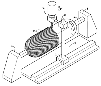
The sole figure shows an example of a device
belonging to the first category. Nevertheless, the
present invention can be implemented equally well by
devices belonging to either of the two categories. In
the figure, the device for making a thermally-protective
coating comprises a mandrel 2, e.g. made of metal,
mounted on a rotary shaft 4 held by a driving headstock 6
and a moving tailstock 8. The mandrel 2 can rotate
continuously in the direction of arrow F. A longitudinal
bench 10 extending parallel to the mandrel 2 serves as a
support for a carriage 12 capable of moving
longitudinally along the bench. A casting head 14 is
carried by the carriage 12 via a pole 16 extending
perpendicularly to the axis of the mandrel and of the
bench. Thus, the casting head 14 can move parallel to
the axis of the mandrel and of the bench in the direction
of arrow D. The casting head 14 is connected via ducts
and metering pumps (not shown) to various receptacles
(not shown) storing the various ingredients of the
coating.
Step a) of the method of the invention consists in
continuously preparing the mixture containing
polyurethane for forming the thermally-protective
coating. By way of example, the polyurethane may be a
pre-polymer of the type having isocyanate terminal
groups. Preferably, the polyurethane pre-polymer is the
result of reacting a polyether with diphenyl-methane-
diisocyanate. The polyurethane is measured out and mixed
in the casting head 14 with polymerization agents that
CA 02512105 2005-06-29
9
have had specific fillers previously dispersed therein.
For this purpose, the polyurethane, the or the various
polymerization agents) (catalysts), and the various
fillers are each stored in respective receptacles. Then
by using ducts and metering pumps connected to those
receptacles, it is possible to convey the desired
ingredients at the desired quantities and rates to the
casting head. Thus, the quantities of the ingredients
may be caused to vary continuously without that
interrupting the casting of the resulting mixture. The
polymerization agents) is/are selected for their
rheological characteristics and their polymerization
characteristics so that the polyurethane goes from a
substantially liquid state on leaving the casting head to
a state that is sufficiently viscous for it to adhere to
the outside surface of the mandrel 2 without running off
it. The "setting time" of the resulting mixture must
therefore be very short. For example, for the
polymerization agents, it is possible to use amines
and/or polyols. In addition, it is preferable to select
fillers that are in powder or fiber form. Powder fillers
can be of the silica type and/or an antimony trioxide,
and/or chlorine-containing compounds, and/or glass
microbeads, and/or silica microbeads, and/or
acrylonitrile microbeads. Fiber fillers may be
discontinuous of the aramid type and/or of the cellulose
type.
In addition, it is possible to adjust the quantities
of the various ingredients making up the mixture while it
is being cast, e.g. in order to make coatings comprising
a plurality of superposed layers each having different
mixture formulations, with changeover from one
formulation to another being progressive or otherwise.
Step b) of the method consists in coating the
outside surface of the mandrel 2 by continuously casting
touching turns of a strip 18 of the mixture as obtained
in this way. The mixture flows from the outlet of the
CA 02512105 2005-06-29
casting head 14 onto the outside surface of the mandrel
and thus forms a continuous strip 18. Since the "setting
time" of the polyurethane is made to be very short by
adding polymerization agents, the strip 18 of mixture
5 gels so as to become viscous and does not run during the
continuous rotation of the mandrel. By adjusting the
quantities of the various ingredients making up the
mixture while casting is taking place (such as the
concentrations of the various polymerization agents), and
10 by adjusting the operating parameters of the coating
device (such as the speed of rotation of the mandrel 2,
the speed of advance of the carriage 12, or indeed the
flow rate of the mixture at the outlet from the casting
head 14), it is possible to cast a strip 18 in accurately
touching turns forming a coating of regular and
calibrated thickness over the entire outside surface of
the mandrel. Nevertheless, it is also possible to
deposit varying thicknesses, and deposition can take
place on surfaces that can equally well be cylindrical or
spherical. In addition, and when making a thick
thermally-protective coating, it is also possible to
perform deposition as a plurality of successive passes
while still maintaining the continuous and automatic
nature of the method.
During step c) of the method, the resulting coating
is pre-polymerized. This pre-polymerization step is
performed at ambient pressure, and advantageously at
ambient temperature. It therefore does not require an
autoclave, thereby considerably reducing the cost of
implementing the method. This pre-polymerization stage
enables the coating to go from a substantially viscous
state to a state in which it is polymerized sufficiently
to be capable of being stressed mechanically, e.g. during
subsequent steps of machining or of providing an outer
winding. This change in state of the coating can be
understood since the liquid polyurethane is mixed with
one or more polymerization catalysts.
CA 02512105 2005-06-29
11
Furthermore, after the pre-polymerization step,
provision can be made to machine the coating so as to
adapt its outside profile to the profile required for
depositing and bonding the casing of the thruster.
A final step of polymerization by hot curing the
coating as pre-polymerized in this way may be provided.
This curing of the coating is likewise performed at
ambient pressure, but in an oven. It enables good
mechanical and thermal properties to be conferred on the
coating. Curing may be performed before depositing and
bonding the casing of the thruster (in particular when
the casing is made of metal), or after the coating has
been deposited and bonded. In particular, when the
casing of the thruster is made by winding a filament of
pre-impregnated fiber material (e. g. winding a filament
of carbon, glass, or polyaramid impregnated in a non-
polymerized thermosetting resin) on the outside surface
of the coating, it is advantageous to polymerize the
coating simultaneous with the stage of polymerizing such
a winding of filament. Under such circumstances, the
simultaneous polymerization step can also make it
possible to obtain the bonding between the coating and
the composite structure via a bonding agent previously
deposited on the outside surface of the coating.
The method of the invention as described above with
reference to the figure is implemented by a device which
forms an internal coating by casting a strip on the
outside surface of a rotating mandrel, the casing of the
thruster being subsequently deposited and bonded on the
coating as formed in this way. The method of the
invention also applies to a device which forms the
internal coating by casting a strip directly onto the
inside surface of the casing of the thruster. Under such
circumstances, the hollow casing of the thruster
structure, made of metal or advantageously out of
polymerized composite material, is made before the
thermally-protective coating, and is set into rotation
CA 02512105 2005-06-29
12
between a driving headstock and a moving tailstock. The
coating device also comprises a casting head capable of
moving inside the casing of the thruster along its
longitudinal axis. The method of making the thermally-
protective coating is identical to that described above.
Prior to the step of continuously casting a strip of the
mixture in touching turns, the inside surface of the
thruster casing is degreased and treated with a bonding
agent. Once the inside surface of the casing has been
coated, the resulting coating is pre-polymerized at
ambient temperature and pressure, and optionally it is
machined. The coating may also be subjected to
polymerization in an oven. In this configuration, the
method of the invention also achieves a saving in terms
of reducing manufacturing costs.
Similarly, the method of the invention may be
applied to making an external thermally-protective
coating for a thruster structure. Such an external
coating is deposited and bonded on an outside surface of
the casing of the thruster structure. This external
thermally-protective coating can be used either on its
own or else in combination with an internal thermally-
protective coating. For a casing of composite material
that is provided both with an internal coating and with
an external coating, it is advantageous to perform
polymerization of both coatings simultaneously with the
stage of polymerizing the winding and filament
constituting the casing.
Bonding between the thermally-protective coatings)
and the casing of the thruster structure is achieved
either by using a bonding agent of known type, or by
using an adhesive film of polyurethane. Such a film is
obtained by metering out polyurethane that has been
specially formulated as an adhesive through the casting
head 14 and it is deposited by being cast as a continuous
strip of touching turns using the method of the
invention. This solution makes it possible to avoid
CA 02512105 2005-06-29
13
using certain known bonding agents such as isocyanates
which are deposited by means of a spray gun and which
give rise to safety and environmental problems since they
require the use of solvents.
Examples of implementations of the method of the
invention have been performed under the following
conditions:
Example 1 (silica-filled polyurethane coating)
The various ingredients defined in Table I below
were measured out and then mixed in the casting head 14
of the casting device shown in the figure.
Table I
Ingredients Parts by weight
MDI - polyether pre-polymer 100
Polytetrahydrofuran 510
Amine mixture 27.7
Silane-treated silica 179
Catalyst 0.4
The resulting mixture was deposited by being cast
continuously as a strip of touching turns on the outside
surface of a rotating cylindrical mandrel (mandrel of
diameter 0.3 meters (m) and of length 1 m). The casting
rate of the mixture, the speed of rotation of the
mandrel, and the travel speed of the casting head were
adjusted so as to deposit a coating having a uniform
thickness of 10 millimeters (mm) in two successive 5mm-
thick passes. After pre-polymerization over about 2 days
at ambient temperature, and polymerization for 2 hours at
140°C (in order to simulate the cycle of polymerizing a
casing of composite material), the coating I as made in
this way was separated from its mandrel in order to be
subjected to certain tests specific to internal thermal
protection, namely: traction strength, thermal resistance
CA 02512105 2005-06-29
14
(thermal conductivity and specific heat), and tests
characteristic of firing (measuring the rate of erosion
under thermal and mechanical attack from propellant
combustion gas). The results of those tests are set out
in Table II below, in comparison with a conventional
thermally-protective coating II made on the basis of a
silica-filled EPDM gum rubber.
Table II
Characteristics Coating I Coating II
Density (g/mL) 1.17 1.1
Breaking strength in 17.1 13
traction (MPa)
Elongation on breaking 380 400
in traction (%)
Secant tensile modulus 4.6 4
at 1000 elongation (MPa)
Thermal conductivity 0.26 0.25
(W/m/C)
Specific heat (J/K/g) 1.76 1.8
Erosion rate during 0.14 0.13
firing (mm/s)
From the results given in this table, it can be seen
that the characteristics of the coating I obtained by the
method of the invention are very close to those of the
coating II as obtained conventionally.
Example 2 (low density coating of polyurethane filled
with glass microbeads)
The various ingredients defined in Table III below
were measured out and then mixed in the casting head 14
of the casting device shown in the figure.
Table III
Ingredients Parts by weight
CA 02512105 2005-06-29
MDI - polyether pre-polymer 100
Polytetrahydrofuran 510
Amine mixture 27.7
Glass microbeads (0.2 g/mL) 96
Catalyst 0.4
The conditions, the deposition tools, and the pre-
polymerization steps of the resulting mixture were the
same as those described for Example 1. After those
5 steps, the resulting coating III was separated from its
mandrel and subjected to tests analogous to those
described above. The results are given in Table IV
below.
10 Table IV
Characteristics Coating III
Density (kg/L) 0.68
Breaking strength in 8
traction (MPa)
Elongation on breaking 440
in traction (%)
Secant tensile modulus 4.6
at 100% elongation (MPa)
Thermal conductivity 0.15
(W/m/C)
Specific heat (J/K/g) 1.75
The densities measured on samples taken from
different points of coating III were about 0.68 g/mL
which is close to the theoretical value (0.66) calculated
15 on the basis of the contents and the densities of the
various ingredients. This shows that the glass
microbeads were relatively unaffected throughout the
stages of mixing the various ingredients. Furthermore,
no material defect was observed of the bubble type or of
poor adhesion between two layers.
CA 02512105 2005-06-29
16
Example 3 (coating with superposed layers corresponding
to different formulations)
The various ingredients of the formulation defined
in Example 1 were measured out and mixed in the casting
head of the casting device. The resulting mixture was
deposited by being cast continuously to form a strip of
touching turns on the outside surface of a rotating
cylindrical mandrel (mandrel of diameter 0.3 m and of
length 1 m). The casting rate of the mixture, the speed
of rotation of the mandrel, and the travel speed of the
casting head were adjusted so as to deposit a layer
having a thickness of 5 mm in a single pass. After pre-
polymerization for 1 hour at ambient temperature, the
method was repeated using the ingredients for the
formulation defined in Example 2. That mixture was cast
in two successive passes each having a thickness of 5 mm
so as to obtain a layer having a thickness of 10 mm.
After pre-polymerization for 2 days at ambient
temperature, and then polymerization for 2 hours at 140°C
(in order to simulate the cycle of polymerizing a casing
of composite material), the resulting coating was
separated from its mandrel and subjected to various
tests. The thicknesses of the layer having the
formulation of Example 1 lay in the range 4.6 mm to
5.2 mm. Similarly, the thicknesses of the layer having
the formulation of Example 2 lay in the range 9.3 mm to
10.1 mm. No bubble type defect or poor adhesion between
the layers was found.
Example 4 (silica-filled polyurethane coating covered in
a carbon-epoxy casing)
The various ingredients of the formulation defined
in Example 1 were measured out and then mixed in the
casting head of the casting device. The resulting
mixture was deposited by being cast continuously as a
strip of touching turns on the outside surface of a
CA 02512105 2005-06-29
17
rotating cylindrical mandrel (mandrel of diameter 0.3 m
and of length 1 m). The casting rate of the mixture, the
speed of rotation of the mandrel, and the travel speed of
the casting head were adjusted so as to deposit a 5 mm
thick layer in a single pass. After pre-polymerization
for 7 days at ambient temperature (in order to simulate
in realistic manner the maximum waiting time that might
occur in an industrial process between the thermally-
protective coating being separated from the mandrel and
the filament of a composite structure being wound
thereon), a carbon fiber wet-impregnated with 120°C class
epoxy resin was wound circumferentially on the coating to
a thickness of about 4 mm. After winding, the mandrel
fitted in this way was put into a ventilated oven for a
polymerization cycle consisting in a temperature rise at
a rate of 1°C per minute up to 140°C, followed by a 2-
hour plateau at 140°C, and a fall in temperature at 1°C
per minute. Machining was used to take test pieces from
the structure as obtained in that way, each piece having
a width of 25 mm, a thickness of about 9 mm, and a
curvilinear length of about 300 mm. Adhesion between the
thermally-protective coating and the casing was tested on
the test pieces using special traction tooling and using
a peeling test with an angle of about 90° between the
casing and the length of coating on which traction was
applied. Under such test conditions, the traction force
needed to separate the coating from the casing was
greater than 25 decanewtons (daN), which corresponds to
good adhesion between those two elements.
The present invention presents numerous advantages,
and in particular:
it makes use of a series of automatic operations
that follow one another in continuous manner. The
coating devices used make it possible to perform
continuous operations of measuring out and mixing the
ingredients and of casting the resulting mixture. The
pre-polymerization of the resulting coating does not
CA 02512105 2005-06-29
18
require passage in an oven, which means that the same
support can be used for the polymerization stage, if any;
it leads to short manufacturing cycles, reducing
the time required and the tooling needed, and thus
reducing the costs of making the coating. In particular,
the number of workstations needed is smaller, since with
a single station it is possible to implement the
following steps: coating, machining, pre-polymerization,
and optionally winding. There is also no need to
separate the coating from its support in order to perform
the polymerization step, thereby simplifying this step of
the method. when the casing of the thruster is made by
winding a filament of composite material, it is also
possible to make direct use of the mandrel that is for
subsequent use in the winding step. It is thus possible
to envisage making large thruster structures; and
it enables a thermally-protective coating to be
obtained that has improved characteristics. It is
possible to make coatings having a plurality of
superposed layers of different compositions (as described
in Example 3). For example, it is possible to deposit a
first layer of suitable thickness that is formulated
specifically to present good resistance to ablation when
subjected to thermal or mechanical attack from the
combustion gas, and a second layer, superposed on the
first, that is formulated specifically to present low
density and low thermal conductivity.