Note: Descriptions are shown in the official language in which they were submitted.
CA 02512368 2005-08-19
WO 2004/075980 PCT/US2003/028980
IONTOPHORETIC DRUG DEhIVERY SYSTEM
BACKGROUND OF THE IN~JEI~fTIOI~
I. Field ~f the In~enti~n
The present invention concerns transdermal delivery of
therapeutic agents by the use of shin worn devices. More
partiCUlarly, the invention is directed to a system that is
wearable and utilises the principle of iontophoresis as a
means of introducing substances into the body. The system
is packaged as a self-contained easily activated system in
the form of a rather small skin worn patch that contains
electrodes and a therapeutic agent. When applied to the
skin, the system completes a circuit and can initiate a
flow and controlled duration of current corresponding to
the desired rate and amount of therapeutic agent to be
delivered.
II. Related Art
The process of iontophoresis was described by ZeDuc in
1908, and has since found commercial use in the delivery of
sonically charged compounds such as pilocarpine,
de~amethasone, and lidocaine. In this delivery method, ions
bearing a positive charge are driven across the skin at the
site of an electrolytic electrical system anode, while ions
bearing a negative charge are driven across the skin at the
site of an electrolytic electrical system Cathode.
With iontophoretic devices, the application time and
level of current flow (usually reported in units of milli-
amp minutes) between the anode and cathode is directly
correlated to the amount of drug delivered. The efficiency
of drug delivery in an iontophoretic system can be measured
by the proportion of current carried by drug molecules,
relative to the current carried by competing non-medication
ions having the same charge as the medication.
Iontophoresis devices conventionally have included two
electrodes attached to a patient, each connected via a wire
CA 02512368 2005-08-19
WO 2004/075980 PCT/US2003/028980
2
to a microprocessor controlled electrical instrument.
Medication is placed under one or both of the electrodes,
for delivery into the body as the instrument is activated.
The instrument is designed to regulate current flow and
application time. Examples of such instruments are
described in patents 5,254~081, and 5,431,625. Power for
these devices is usually provided by DC batteries, which
when providing power for the microprocessor controlled
circuitry allow application of a voltage to the electrodes
to create a regulated current flow. These microprocessor
systems are disadvantaged by the fact that patients are
'attached by wire' to an instrument, which limits patient
mobility and ability to conduct normal daily activities. A
typical application period for creation of skin anesthesia
is approximately 10-20 minutes, which consumes instrument,
caregiver, and patient time.
More recently, wearable iontophoretic systems have
been developed in which the electrical circuitry and power
supplied are integrated into a single patch. These systems
are advantageous in that they do not have external wires,
and they are much smaller in size. Examples of such
systems can be found in U.S. patents 5,358,483; 5,458,569;
5,466,217; 5,605,536; and 5,651,768.
Typically, drug ions are delivered into the body from
an aqueous 'drug' reservoir contained in the iontophoretic
device, and counter ions of opposite charge are delivered
from a 'counter' reservoir. A critical step in
iontophoresis involves the process for incorporation of
drug ions and counter ions into the device. It is well
know that if such a device is improperly loaded, the device
will not perform as desired.
Most often, drug/ion solutions are stored remotely in
bulk quantity and introduced to an absorbent layer of the
iontophoresis electrode at the time of use. Examples of
CA 02512368 2005-08-19
WO 2004/075980 PCT/US2003/028980
3
such systems are described in patents 5,087,241; 5,087,242;
5,846,217~ and 6,421,561. An advantage to this approach is
that the electrodes are packaged and stored in a dry state,
which is optimal for shelf life. t~ disadvantage to this
approach is that the electrodes can be easily over-filled
or under-filled, thus this aspect requires trained
personnel with good technique. Additionally, because the
drug solution is stored separately from the electrodes,
management of two inventories is required.
To avoid the need for users to incorporate the aqueous
drug or ion reservoir at the time of use, the drug solution
can be pre-packaged into the electrode. Unfortunately, this
inevitably reduces shelf life. During storage, moisture
emanating from the drug solution can be absorbed into
adjacent materials, resulting in corrosion of metallic
components, degradation of power sources, and inadequate
hydration of the drug pad. Patents 5,738,647 and 5,817,044
discloses a device where an aqueous reservoir is stored in
contact with an electrode assembly, and a dry medicament
layer introduced to the aqueous reservoir at the time of
use. Unfortunately, with this configuration the electrode
is still stored in wet environment, and is therefore
susceptible to corrosive deterioration.
In patent 5,685,837, a system is described in which a
drug of interest, in a dry form, is pre-packaged into the
electrode(s). This offers two advantages. First, moisture
is not present to compromise the integrity of metallic
electrode components during storage, and second, the drug
of interest remains very stable. This offers a particular
advantage for the delivery of certain drugs, such as large
CA 02512368 2005-08-19
WO 2004/075980 PCT/US2003/028980
4
polypeptides, which have a poor stability in solution form.
However, this approach requires a moisture activation step
at the time of use, which can in~-olve a time dela~i or
introduce a reason for mechanistic failure.
Many patents describe systems where drug solutions are
co-packaged with the iontophoretic device, but positioned
apart from the electrodes and other metallic components
until an 'activation' step is implemented at the time of
use. Patents 5,158,537; 5,288,289; 5,310,404; 5,320,598;
5,385,543; 5,645,527; 5,730,716; and 6,223,075 describe
such devices. In these devices, a co-packaged electrolyte
constituent liquid is stored remotely from the electrodes,
in a rupturable container and a mechanical action step at
the time of use induces a fluid transfer to a receiving
reservoir adjacent to the electrodes. These systems enable
precise fluid volumes to be incorporated at the time of
manufacture to avoid overfilling; however, these devices
are mechanically complex, and can fail if, for example, the
package is squeezed during shipping, the container breaks
and fluids are pre-maturely released. Other failure modes
include compromising of the fluid delivery path during
storage, if f or example, outgassing hydrophobic plasticizer
material is absorbed into the fluid channel, inhibiting the
transfer of fluid at the time of use.
Another strategy to incorporate drug into the
iontophoretic device is described in U.S. Patent 4,383,529.
In that disclosure, a preformed gel containing the drug is
transferred into an electrode receptacle at the time of
use. The advantages of this system include the provision of
a precise pre-determined volume of drug gel to prevent
over-filling, and the.fact that using the gel form of the
drug matrix insures that liquid will not 'leak' during
storage or transfer. A significant disadvantage to the
device described, however, el~ists because the user is
CA 02512368 2005-08-19
WO 2004/075980 PCT/US2003/028980
required to visually align the gel into the receptacle at
the time of use, which is a process that may be difficult
for elderly patients. Additionally, that device requires
the user to apply a mucilage material to the electrode
5 prior to incorporating the gel so as to insure the
integrity of the electrical contact between the electrode
and the drug gel. Furthermore, it is necessary at the time
of use to rotate the gel over the mucilage layer to remove
entrapped air, which introduces another technique-dependant
source of error. Finally, the gels of interest are stored
separately from the electrodes in a plastic bag, or the
like, and this requires management and storage of two
separate components.
Thus, while there exists a variety of devices in the
class, each of which has certain attributes, there remains
a need for a single iontophoretic drug delivery system that
combines the desired attributes and eliminates the
drawbacks recited above. The present invention provides
such a device in the form of an iontophoretic drug delivery
system that is reliable, self-contained, simple to use, and
shelf-stable.
SLIMhIARY OF THE INVENTION
The present invention solves many of the problems
associated with prior self-contained iontophoretic drug
delivery systems by the provision of a reliable, self
contained system which enjoys a long stable shelf life and
which is also quite easy to use. The present invention
Contemplates a wearable iontophoretic device that is pre-
packaged as a complete self-contained unit which includes
the active species or drug to be administered and counter
ions. The system includes a provision for isolating
moisture sources from the electrodes and from the power
source during storage to optimize shelf stability. The
inventive systean provides a simple, user-friendly mechanism
CA 02512368 2005-08-19
WO 2004/075980 PCT/US2003/028980
6
to transfer the drug to be administered and counter ion
reservoirs to the electrodes in order to activate the
device circuit. The self-contained iontophoretic drug
delivery system of the present invention contemplates the
storage of all elements of the device in a single device to
be activated in a single outer package. Depending on the
drug or other therapeutic active species to be
administered, the particular ion species may be selectively
or optionally stored in either a dry state or a wet state
in order to optimize shelf stability.
It is an important aspect of the present invention
that it provides a complete, self-contained packaged device
that includes all of the components necessary for
iontophoretic delivery, including a wearable device; an
aqueous anodic matrix; and an aqueous cathodic matrix. All
three components (as stored) are carried on a thin, planar
substrate, which additionally serves as a release liner,
that is removed during device activation. No external
components need to be included. If the active species or
drug to be delivered is of a positive charge, it is
associated with the anodic electrode, if the drug to be
delivered is of a negative charge, it is associated with
the cathodic electrode.
The entire device including the substrate and its
components are packaged together, preferably in a
conventional medical foil storage pouch or the like (not
shown in figures). Within the foil pouch, the cathodic and
anodic aqueous matrixes are each isolated from the
iontophoretic device by a water impermeable release
membrane which is peeled away and removed at the time of
activation. In the event that the drug to be delivered
remains stable when dissolved in an aqueous solution, the
drug is incorporated into the appropriate aqueous matrix at
the time of manufacture. If, however, the drug has a
CA 02512368 2005-08-19
WO 2004/075980 PCT/US2003/028980
7
limited shelf stability when dissolved, the drug is
incorporated as a dry layer adjacent the related electrode
of the iontophoretic device, and dissolved into the aqueous
matrix at the time of activation.
The activation and placement of the device is rapid
and simple. First, the sealed storage pouch is breached
revealing the substrate and its three components with the
cathodic and anodic aqueous matrices remaining isolated
from the iontophoretic device separated by the water
impermeable membranes indicated above. To activate the
device, water impermeable membrane covers which is~late the
cathodic and anodic aqueous matrices are simply peeled away
and removed. The substrate is then folded inward on itself
at predetermined locations to engage the aqueous matrices
with the iontophoretic device. For this purpose, one or
more clearly visible fold lines are preferably provided on
the substrate to insure proper alignment as the device is
folded. An adhesive material provided on the iontophoretic
device serves to secure the aqueous matrices to the device
as they are engaged during the folding step. Engagement of
the aqueous matrices, activates the device and the then
activated device can be removed from the substrate or
release liner ply and be placed on the body to begin drug
delivery.
A key element to this invention is the ease of
successful transfer of the anodic and cathodic aqueous
matrices to the iontophoretic device at the time of
activation which is facilitated by the incorporation of
fold lines (which may be score lines, perforations or the
like) that insure proper folded alignment. Additionally,
the matrices need to be kept in place during the act of
folding the substrate. While this can be accomplished in
various ways, preferably a minor amount of releasing
packaging adhesive material is provided to hold the
CA 02512368 2005-08-19
WO 2004/075980 PCT/US2003/028980
8
matrices in place. Alternatively, they may be held in
place without adhesives by containment in a recessed
portion provided in the sukastrate. Successful transfer of
the matrix t~ the iontophoretic device requires that an
adhesive present on the surface of the receiving device
(transfer adhesive) form a bond that is stronger than that
of the packaging adhesive material that fixed the matrices
to the release liner or substrate. It has also been found
that the adhesive material on the iontophoretic device
should ideally surround at least a portion of the
electrode, so as to maintain adequate contact between the
electrode and matrix during the iontophoresis process.
BRIEF DESCRIPTION OF THE DRAWINGS
In the drawings wherein like numerals depict like
parts throughout the same:
Figure 1a is an exploded schematic view of one
embodiment of a device constructed in accordance with the
invention as it is packaged and stored;
Figure 1b is a schematic cross sectional view of the
embodiment of Figure 1a as assembled;
Figures lc and 1d represent cross sectional and top
views depicting an alternative embodiment of an anode or a
cathode matrix;
Figure 2 is a top view of the embodiment of Figures 1a
and 1b;
Figures 3a-3e are schematic cross sectional views of
the device of Figure 1, during stepwise activation for use;
Figure 4 is a schematic cross sectional view of an
alternate embodiment of the device of the invention;
Figure 5 is a top view of another embodiment of the
device of the invention;
Figure 6 is a top view of an alternate configuration
of the device of Figure 5a
CA 02512368 2005-08-19
WO 2004/075980 PCT/US2003/028980
9
Figure 7 is a top view of an alternate embodiment of
the device of Figure 1, in which the drug is stored in a
dry state and dissolved at the time of activationa
Figure 8 is an electrical schematic of a preferred
circuit for rate regulations and
Figure 9 is a top view of a two-position embodiment of
the device of the invention suitable for the delivery
system of fentanyl citrate as a means of pain management.
DETAaLE~ DESCRZPTa~r~
The present invention provides a fully self-
contained easy-to-use iontophoresis system in a single
pre-packaged unit. Nothing needs to be added to the pre-
packaged unit for activation and use. Except for the
removal of release liners or backing layers and one or
more simple folding operations, the device is completely
ready to use. Several possible preferred embodiments of
devices encompassing the inventive concepts will next be
described. These embodiments are presented to illustrate
the concepts of the invention and they are not meant to
be construed as limiting in any manner.
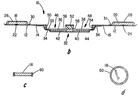
Thus Figures 1a, 1b and 2 depict respectively an
exploded view, a cross-sectional elevational view and a
top view of one embodiment of such a device, generally at
10, as it is packaged and stored. The device 10 is
stored as an elongated device designed to fold on itself
when activated and used to form a compact skin-worn drug
applicator. It includes a continuous backing or
substrate layer 12 which is also designed as a release
layer, as will be seen, provided with fold lines as at 14
and 16, respectively. An anode matrix 18 and cathode
matrix 20 are respectively releasably adhered to the
peel-away backing or continuous substrate layer 12 by
rather smaller su ed amounts of packaging adhesive
release or transfer layers 22 and 24. The substrate
CA 02512368 2005-08-19
WO 2004/075980 PCT/US2003/028980
layer 12 is generally a thin, water impermeable layer of
a material such as polycarbonate, polyethylene,
polypropolene or the like. Moisture impermeable covers
26 and 28 are in the nature of release coating layers
5 that serve as protective barriers during storage of the
anode matrix 18 and cathode matrix 20, respectively. The
moisture impermeable covers 26, 28 include pull-tab
devices as at 30 and 31 for easy peel-away removal at the
time of device activation.
10 An iontophoretic circuit device, generally depicted
by 32, is fixed to the opposite side of substrate 12 as
by an adhesive-coated backing layer 34. The
iontophoretic device 32 further includes an anode 36 and
a cathode 38 electrically connected to an optional or
selectively used electronic circuit depicted by 40
utilizing of electrically conductive layers 42 and 44,
respectively.
The optional electronic circuit 40 is preferably of
a known conventional type and includes a power source,
resistors, switches and other conventional circuit
components. These systems are well known to those
skilled in the art as useful for controlling current flow
and so need not be described here in greater detail. In
the absence of the selective or optional electronic
circuit 40, power for the device may be provided by
spontaneous or galvanic means using oxidizing and
reducing coatings, on the anode (for example, Zinc) and
the cathode (for example, Silver Chloride).
The device as stored includes a pair of empty
recesses or chambers 46 and 48 defined by portions of
structural layers as at 50, 52 and 54 as best seen in the
top view of Figure 2, which are preferably made of
pliable material such as a closed cell polyurethane foam,
or the like. The empty chambers 46 and 48 are sized so
CA 02512368 2005-08-19
WO 2004/075980 PCT/US2003/028980
11
as to receive cathode matrix 18 and anode matrix 20,
respectively. Corresponding openings 46a and 48a are
provided in the release layer 12. Fold lines 14 and 15
are located at the midpoint between the respective
matrices 18 and 20 and chambers 46 and 48, respectively,
and are positioned and angled such that the matrices are
aligned to be received in the empty chambers when the
substrate is folded during the activation sequence as
will be described. Whereas the fold lines are depicted
as a notch in the figures, those skilled in the art will
recognize that there are many alternate ways to
predetermine a line of preferential folding, such as
using perforations, score lines, hinges, etc.
The bottoms of chambers 46 and 48 are provided with
areas of transfer receiving adhesive layers at 56 and 58,
respectively, which are designed to secure the matrices
18 and 20 to the electrodes 36 and 38, respectively of
the iontophoretic device 32 as they are transferred from
the packaging substrate 12 as the device is activated.
Figure 1c shows an exploded view of a matrix system for
either an anode or cathode similar to that shown in
Figure 1a with the exception that a structural ring 60 is
provided surrounding the matrix. The structural ring 60
is designed to transfer into the corresponding opening as
at 46 in the activated device with the matrix 18.
Figures 3a-3e illustrate the steps in the activation
process for the embodiment of the device depicted in
Figures 1 and 2. Tn Figures 3a and 3b the pull-tabs 30,
31 have been utilized to remove the moisture impermeable
membrane release liners or covers 26 and 28 from the
matrices 18 and 20. As illustrated in Figures 3c and 3d,
the substrates 12 and 13 are then folded respectively at
fold lines 14 and 16 to engage the matrices 18 and 20
with the iontophoretic device 32. The matrices 18 and 20
CA 02512368 2005-08-19
WO 2004/075980 PCT/US2003/028980
12
are secured in place on the iontophoretiC device 32 by
the adhesive at 56 and 58. This enables the substrate or
bacl~ing layer 12 to be tcatally stripped array without
disturbing the matrices 18, 20 which are also within
openings 4~a and 48a thereby exposing the adhered
matrices so that the device can be turned over at Figure
3e and applied to the skin of a patient utilizing the
adhesive on the adhesive-coated backing layer 34, which
also Completes the circuit and thereby activates the
device to initiate the transfer of the drug of interest.
Figure 4 is a schematic cross-sectional view of an
alternate configuration 62 of the device 10 of Figure 1.
In this embodiment, anode matrix 18 and cathode matrix 20
are contained in recessed portions 64 and 66 of substrate
12, respectively. Moisture impermeable release covers 26
and 28 are utilized as in the previous embodiment along
with removing pull-tabs 30 and 31. This embodiment,
however, eliminates the need for the adhesive layers 22
and 24 to maintain the matrices 18 and 20 in place prior
to activation. This embodiment is particularly useful
for situations in which the drug ions are not stable in
the presence of adhesive material 22, 24.
Figure 5 depicts another alternative embodiment in
the form of a side-by-side arrangement at 70 in which the
drug-containing matrices 18 and 20 are located on one
side and the iontophoretic device is located on the
other. A single fold line 72 separates the two and is
all that is needed to transfer the matrices to the
iontophoresis device for activation.
Figure 6 depicts yet another embodiment 80, which is
similar to the embodiment of Figure 5 including a single
fold line at 82, the only difference being the use of the
single moisture impermeable release cover 84 with single
corner pull-tab 86 to cover both matrices 18 and 20.
CA 02512368 2005-08-19
WO 2004/075980 PCT/US2003/028980
13
This, of course, simplifies the activation process by
accomplishing the peel-away removal of the matrix cover
fr~am both matrices in a single step.
Figure 7 depicts a view similar t~ Figure 2 of an
embodiment that is similar to that depicted in Figures
1a, 1b and 2 but in which an additional drug layer
depicted through opening 90 is incorporated into the
iontophoretic delivery device 32 at the appropriate
electrode 36. This configuration can be used in lieu of
incorporating the drug in the matrix 18 as illustrated,
or 20 as the case may be, when the drug is not stable
over time in an aqueous matrix. The drug layer seen at
90 is in a dry state and may be incorporated into a
filter pad or other suitable water soluble or insoluble
matrix during storage. Upon activation, the drug layer
at 90 is dissolved into either the anode gel matrix, as
illustrated, or the cathode gel matrix 20, depending on
the charge of the drug.
The aqueous matrices 18 and 20 in this invention are
preferably formed of a hydrophilic gel material, to insure
that the matrix maintains a uniform structure during the
folding process. Obviously, if the matrix were in a low
viscosity, e.g. liquid state, it would deform during the
fold process. It has been found a 1-3o agarose, or 10-120
cross linked polyvinyl alcohol to be an acceptable examples
of gel for this purpose. Substances which provide a high
viscosity, such as polyvinylpyrrolidone, methyl cellulose,
hydroxypropyl methylcellulose, carboxymethyl cellulose are
also acceptable. Those skilled in the art will recognize
the benefit of also incorporating additives such as
humectants (ex guar gum) and anti-fungal agents (ex. methyl
or butyl paraben). Further, it has been found beneficial
to incorporate a fibrous material such as cellulose,
polyester, or polypropylene into the matrix. This fibrous
CA 02512368 2005-08-19
WO 2004/075980 PCT/US2003/028980
14
material serves several purposes~ first, it serves to
provide a defined shape for disperse of the aqueous
solution during the manufacturing process. Second, it
serves to help retain the shape of the matrix during the
folding process. And third, it has been discovered that the
fibrous material serves as a basis for proper adhesion. For
example, an aqueous agarose hydrogel has been found to
adhere very poorly to conventional medical adhesives, as
found on for example medical tapes. However, the same gel
solutions present in a fibrous matrix have been found to
adhere very well.
One preferred use of the delivery system of this
invention is for the delivery of the opioid compound
fentanyl, as a means of managing pain due to, for example,
the effects of chronic cancer. Fentanyl is a highly potent
compound, and a very dangerous one in that, for example,
too high of a dosage rate can lead to a respiratory
depression. Transdermal delivery of fentanyl can be
accomplished passively, when the drug is in the free base
form, as the commercial product DuragesiC (Johnson &
Johnson). Fentanyl is iontophoreseable when formulated as
an ionized hydrochloride or citrate salt, and is positively
charged and therefore deliverable from the anode. An
advantage of iontophoresis is derived from improved control
opportunity; for example, a more rapid onset of action
possible with iontophoresis as compared to passive
introduction. Since the ionic form of fentanyl is not
passively permeable through skin, theoretically, the rate
and amount of fentanyl delivered can be regulated entirely
by current flow. IontophoretiC devices for the delivery of
fentanyl are described in LT. S. Patents 5,232,438, 6,171,24
and 6,216,033. In these devices, an activation switch
initiates a pre-determined DC Current flow (regulated by
electronic circuitry) over a pre-determined timing (e.g. up
CA 02512368 2005-08-19
WO 2004/075980 PCT/US2003/028980
to 20 minutes) interval to provide a bolus dose of fentanyl
on the order of 60 micrograms.
It has been discovered according to the present
invention that voltage regulation is a preferred and safer
5 alternative to current regulation in the iontophoretic
delivery of fentanyl. In current regulation, when the
device is activated, an electronic circuit automatically
adjusts an applied voltage to achieve a known current
level. The necessary voltage is dependant on, among other
10 things, the desired current level and patient skin
resistance. Upon initiation of current, the skin is often
dry, the applied voltage is therefore very high, and a high
current density will be focused on an area of skin with the
least amount of resistance. This concentration of current
15 can itself cause skin damage to the local site, and lead to
a compromise in skin integrity that can lead to passive
transfer with otherwise non-passively transferable fentanyl
ion. Therefore, control of total drug delivery is
compromised in that it is no longer controlled by
iontophoresis alone.
In voltage control, a fixed voltage is applied between
electrodes, and the resulting current will vary in
accordance to skin resistance (e. g. Ohms Law). It has been
found that current will slowly increase over the course of
time, as the skin hydrates under the electrodes and
therefore becomes less resistive. Also, even though the
process is slower, skin integrity is preserved in a
preferred way for iontophoretic fentanyl delivery. With a
voltage controlled circuit, current flow can be regulated
in quasi fashion with incorporation of internal resistance
to the fixed voltage source. In this way, the total system
resistance is a function of skin resistance combined with
internal circuit resistance. If the internal circuit
resistance is high relative to skin resistance, the rate
CA 02512368 2005-08-19
WO 2004/075980 PCT/US2003/028980
16
variability owing to patient-to-patient, site-to-site, and
hydration rate differences are reduced. It has been
discovered that voltage control in the range of 3-12 volts,
with internal resistances in the range of 5-300 kohms are
preferred, as they are adequate for rate control and for
the preservation of skin integrity.
A significant disadvantage to passive delivery is
derived from an inability to modulate delivery rate in a
reversible fashion. This is a significant disadvantage in
delivery of pain management drugs such as fentanyl, in that
pain is generally not constant. In a current regulated
iontophoretic system, the delivery rate is reversibly
adjustable by raising or lowering an applied voltage to
achieve a desired current level. However, this current
regulating approach may lead to unacceptable skin damage,
as described above. A simple two-level delivery rate,
using a voltage regulating electronic circuit, has been
discovered to be sufficient for pain management
applications, where the level is adjusted by reversibly
short circuiting a portion of the internal resistance.
Figure 8 is an electrical schematic of the preferred
2-level delivery rate regulating electronic circuit 100
having a patient adjustable switch 102 shown in the "low"
position with both R1 and R2 in series in the circuit.
Figure 9 is a top view of an activated, fentanyl delivery
device in accordance with the invention 110 with a patient
adjustable two-position rate switch 112. Though they
wouldn't be visible from the top, the electrodes are
depicted with broken lines at 114 and 116 in Figure 9. As
shown, the device is in a "high'° delivery rate status with
a switch type connection engaged to reduce internal device
resistance.
This invention has been described herein in
considerable detail in order to comply with the patent
CA 02512368 2005-08-19
WO 2004/075980 PCT/US2003/028980
17
statutes and to provide those skilled in the art with the
information needed to apply the noel principles and to
construct and use such specialised components as are
required. However, it is to be understood that the
invention can be carried out by specifically different
equipment and devices, and that various modifications, both
as to the equipment and operating procedures, can be
accomplished without departing from the scope of the
invention itself.
What is claimed is: