Language selection

Search

Patent 2512888 Summary

Third-party information liability

Some of the information on this Web page has been provided by external sources. The Government of Canada is not responsible for the accuracy, reliability or currency of the information supplied by external sources. Users wishing to rely upon this information should consult directly with the source of the information. Content provided by external sources is not subject to official languages, privacy and accessibility requirements.

Claims and Abstract availability

Any discrepancies in the text and image of the Claims and Abstract are due to differing posting times. Text of the Claims and Abstract are posted:

  • At the time the application is open to public inspection;
  • At the time of issue of the patent (grant).
(12) Patent Application: (11) CA 2512888
(54) English Title: DEVICE FOR FASTENING DOOR HANDLES
(54) French Title: DISPOSITIF POUR LA FIXATION DE POIGNEES DE PORTE
Status: Deemed Abandoned and Beyond the Period of Reinstatement - Pending Response to Notice of Disregarded Communication
Bibliographic Data
(51) International Patent Classification (IPC):
  • E05B 03/04 (2006.01)
  • E05B 01/00 (2006.01)
(72) Inventors :
  • KREYENBORG, RALF (Germany)
(73) Owners :
  • DORMA GMBH + CO. KG
(71) Applicants :
  • DORMA GMBH + CO. KG (Germany)
(74) Agent: NORTON ROSE FULBRIGHT CANADA LLP/S.E.N.C.R.L., S.R.L.
(74) Associate agent:
(45) Issued:
(86) PCT Filing Date: 2004-08-17
(87) Open to Public Inspection: 2005-03-31
Availability of licence: N/A
Dedicated to the Public: N/A
(25) Language of filing: English

Patent Cooperation Treaty (PCT): Yes
(86) PCT Filing Number: PCT/EP2004/009187
(87) International Publication Number: EP2004009187
(85) National Entry: 2005-07-07

(30) Application Priority Data:
Application No. Country/Territory Date
103 40 562.3 (Germany) 2003-09-01

Abstracts

English Abstract


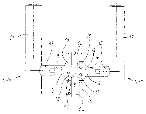
The invention relates to a device for fastening door handles (3). A pocket
bore (4) is provided on each door handle (3) for accommodating a pin (8) that
can be locked by means of each door handle (3). The invention is characterized
in that the opposite door handles (3) of an armature are embodied in an
identical manner while several centering bores (13) into which a threaded
screw (15) is to engage are disposed on one of the two final sections (7) of
the pin (8), said centering bores (13) being offset both in the
circumferential direction and relative to the longitudinal axis (12) of the
pin (8).


French Abstract

L'invention concerne un dispositif de fixation de poignées de porte (3), procédé selon lequel un trou borgne (4) est ménagé sur chaque poignée de porte (3) pour recevoir un goujon (8) pouvant être bloqué avec chaque poignée de porte. L'invention est fondée sur le fait que les poignées de porte (3) opposées d'une ferrure sont identiques et que sur une des deux parties d'extrémité (7) du goujon (8) sont formés, pour l'insertion d'une vis (15), plusieurs alésages (13) qui sont décalés tant dans le sens circonférentiel que par rapport à l'axe longitudinal (12) du goujon (8).

Claims

Note: Claims are shown in the official language in which they were submitted.


-6-
Claims
1. Device for fastening door handles (3) which are arranged opposite one
another on both sides of a door leaf (1) and which each have a pocket hole (4)
for
receiving a pin (8) whose middle portion (5) extends through the door leaf (1)
and whose
end portions (6, 7) can be locked in the oppositely-located pocket holes (4),
wherein a
circumferential groove (9) is provided at a first end portion (6) of the pin
(8) and a
threaded screw (11) which penetrates a transverse bore hole (10) in the door
handle (3)
can be adjusted against the circumferential groove (9), wherein the oppositely
located
door handles (3) of a fitting are identically constructed, and a plurality of
drill holes (13)
are arranged at the second end portion (7) of the pin (8) so as to be offset
in
circumferential direction (arrow A) and relative to the longitudinal axis (12)
of the pin (8)
for the engagement of a threaded screw (15) penetrating a second transverse
bore hole
(14) of the door handle (3).
2. Device according to claim 1, characterized in that the drill holes (13) are
arranged so as to be offset, respectively, by about 120° in
circumferential direction (arrow
A).
3. Device according to claims 1 and 2, characterized in that the offset of
adjacent drill holes (13) in direction of the longitudinal axis (12) of the
pin (8) is a fixed
amount.
4. Device according to one of claims 1 to 3, characterized in that the door
handle (3) is formed as a push handle (16) and comprises a handle (17)
extending parallel
to the door leaf (1) and a brace (18) which extends orthogonal to the handle
(17), is
directed against the door leaf (1) and has the pocket hole (4).
5. Device according to one of claims 1 to 4, characterized in that the
transverse bore holes (10, 14) are arranged in a diametral enlargement (19) of
the brace
(18), which diametral enlargement (19) is arranged in the area of contact at
the door leaf.
6. Device according to one of claims 1 to 5, characterized in that the handle
(17) and the brace (18) are formed integral with one another.

Description

Note: Descriptions are shown in the official language in which they were submitted.


CA 02512888 2005-07-07
DEVICE FOR FASTENING DOOR HANDLES
Description
The invention is directed to a device for fastening door handles which are
arranged
opposite one another on both sides of a door leaf and which each have a pocket
hole for
receiving a pin whose middle portion penetrates the door leaf and whose end
portions can
be locked in the oppositely-located pocket holes. A circumferential groove is
provided at
a first end portion of the pin and a threaded screw which penetrates a
transverse bore hole
in the door handle can be adjusted against this circumferential groove.
In door handles of the generic type mentioned above, not only is there a
demand for
an optically attractive design, but economical manufacture and multipurpose
use are also
required, i.e., particularly the ability to use a fitting comprising two
oppositely located
door handles in door leaves of different thickness. With respect to glass
doors, for
example, the commercially available glass doors that are used have a glass
thickness of 8
to 12 mm.
The generic AT-PS 336 435 shows a possibility for adapting to different
thicknesses
of a door leaf. In the previously known device, one of the two oppositely
located door
handles has a pocket hole with an internal thread into which an end portion of
a pin can
be screwed to a desired depth, while the other door handle holds the second
end portion
of the pin with a pocket hole and can be secured to the pin by a threaded
screw which
penetrates a transverse bore hole of the door handle and engages in a
circumferential
groove of the pin. It is possible through the selection of the screw-in depth
of the pin to
adapt to different thicknesses of a door leaf. However, the arrangement of an
internal
thread in one of the two door handles is compulsory, i.e., every fitting
comprising two
door handles requires two different door handles which are not
interchangeable. The
production of the internal thread and the necessary manufacture of differently
formed
door handles makes the fitting expensive.
A similar device is disclosed in GB-PS 1 155 333, in which an end portion of a
pin
likewise engages in a pocket hole of a door handle by means of a screw thread,
while a
trough-shaped recess which extends in direction of the longitudinal axis of
the pin and in
which a threaded screw penetrating the transverse bore hole of the door handle
engages is

CA 02512888 2005-07-07
-2-
arranged in the other end portion. In this case, again, a fitting requires
that two
differently formed door handles.
Further, AT 003 665 U1 discloses the fastening of oppositely located door
handles to
door leaves of different thickness in which pairs of countersinks are
distributed over the
circumference of the corresponding pin so as to be offset by about 120°
relative to one
another. Accordingly, by rotating the pin it is possible to adjust the fitting
to the
thickness of the door leaf.
It is the object of the invention to optimize the manufacture of door handles,
particularly of so-called push handles, while taking into account the
possibility of
adapting to different thicknesses of a door leaf, particularly of glass doors,
and preserving
an attractive visual form.
The above-stated object is met by the invention through the teaching of claim
1.
According to the invention, the means required for adapting to different
thicknesses
of a door leaf are not components of the door handle, but rather of the pin,
i.e., the
oppositely located door handles of a fitting can advantageously be identically
constructed,
while rotating the pin around its longitudinal axis makes it possible to adapt
to different
thicknesses of a door leaf. In the present case, the maximum adjustment is
several
millimeters, which is generally considered adequate for glass doors. When a
more
extensive adjustment is required, it is sufficient merely to exchange the pin
for a pin with
correspondingly offset drill holes while retaining the same door handles.
Accordingly,
the invention makes it possible to adapt to door leaves of different thickness
in a
technically advantageous manner without the need for different constructions
of the two
oppositely located door handles forming a component of the fitting. This
results in
economical manufacture aid inventory. The door handles themselves
advantageously
comprise special steel, but can be manufactured from any material in
principle.
Further advantageous developments of the invention are the subject matter of
the
dependent claims.
When used in glass doors, it has proven sufficient to provide a plurality of
drill holes
in the pin, preferably three drill holes which are arranged so as to be offset
by about 120°

CA 02512888 2005-07-07
-3-
in circumferential direction. The offset of adjacent drill holes in direction
of the
longitudinal axis of the pin is a fixed amount determined by the thickness of
the different
panes of glass. These offsets can be jumps of 2 mm, for example. This results
in a
maximum adjusting range of several millimeters. The adjusting jump of fixed
amount
does not impair the fixed contact of the door handle at the door leaf because
the door
handle can be cushioned easily by flexible means arranged between the door
handle and
the door leaf when using glass doors, e.g., by means of a corresponding glass
protector.
In a further development of the invention, it has proven advantageous,
particularly
with door handles constructed as push handles, that the push handle comprises
a handle
extending parallel to the door leaf and a brace which extends orthogonal to
the handle, is
directed against the door leaf and has a pocket hole, wherein the transverse
bore holes are
arranged in a diametral enlargement of the brace that is arranged in the area
of contact at
the door leaf. Due to the material amassed in the contact area, for example,
of a pane of
glass, the above-mentioned embodiment form ensures that the contact surface of
the door
handle at the pane of glass is larger than the diameter of the brace and
ensures a sufficient
screw-in depth for the threaded screws. The screw-in depth is so dimensioned
that the
screwed in, i.e., tightened, threaded screw in a visually advantageous manner
does not
project over the diametral enlargement. Further, an advantageous covering of
the glass
protector is ensured in a manner to be described in the following, e.g., in
glass doors.
In a further development of the invention, the handle and the brace are
constructed in
one piece.
The invention will be described more fully in the following with reference to
an
embodiment example:
Figure 1 shows a view of a door handle arranged on both sides of a door leaf;
Figure 2 shows the pin by itself;
Figure 3 shows a section III-III according to Figure 2.
As is shown in Figure 1, two door handles 3 which are identically constructed
push
handles I6 in the embodiment example are arranged on both sides of a door leaf
1 formed
as a glass pane 2. Each push handle 16 comprises a handle 17 and a brace 18
formed

CA 02512888 2005-07-07
-4-
integral therewith. The braces 18 each have a pocket bore 4 in which a pin 8
is inserted
so as to penetrate the glass pane 2 by its middle portion 5. The thickness of
the glass pane
2 is designated by D in the present case.
As can be seen particularly from Figure 2, the pin 8 leas a first end portion
6 and a
second end portion 7. A circumferential groove 9 is provided in the area of
the end
portion 6, while three drill holes 13 are arranged in en3 portion 7 so as to
be offset,
respectively, by 120° in circumferential direction A (see Figure 3). As
is further shown in
Figure 2, the drill holes 13 are offset relative to one another in direction
of the
longitudinal axis 12 of the pin 8 in addition.
According to Figure 1, the braces 18 have diametral enlargements 19 in the
area of
contact with the glass pane 2. Transverse bore holes 10 and 14 which receive
threaded
screws 11 and 15 are introduced in these diametral enlargements 19. It can be
seen that
the threaded screw 11 engages in the circumferential groove 9, while the
threaded screw
can be screwed into one of the drill holes 13 so as to adapt to different
thicknesses D
15 of the glass pane 2. In the present case, a flexible glass protector 20 is
embedded in the
glass pane 2 on both sides, which ensures a reliable contact of the braces 18
at the glass
pane 2.

CA 02512888 2005-07-07
-5-
Reference Numbers
1 door leaf
2 glass pane
3 door handle
4 pocket hole
middle portion
6 end portion
7 end portion
8 pin
9 circumferential
groove
10transverse bore
hole
11threaded screw
12longitudinal axis
13drill holes
14transverse bore
hole
15threaded screw
16push handle
17handle
18brace
19diametral enlargement
20glass protector
A arrow direction
D thickness

Representative Drawing
A single figure which represents the drawing illustrating the invention.
Administrative Status

2024-08-01:As part of the Next Generation Patents (NGP) transition, the Canadian Patents Database (CPD) now contains a more detailed Event History, which replicates the Event Log of our new back-office solution.

Please note that "Inactive:" events refers to events no longer in use in our new back-office solution.

For a clearer understanding of the status of the application/patent presented on this page, the site Disclaimer , as well as the definitions for Patent , Event History , Maintenance Fee  and Payment History  should be consulted.

Event History

Description Date
Application Not Reinstated by Deadline 2007-08-17
Time Limit for Reversal Expired 2007-08-17
Deemed Abandoned - Failure to Respond to Maintenance Fee Notice 2006-08-17
Inactive: IPC from MCD 2006-03-12
Inactive: Cover page published 2005-09-27
Letter Sent 2005-09-23
Correct Applicant Requirements Determined Compliant 2005-09-23
Inactive: Notice - National entry - No RFE 2005-09-23
Application Received - PCT 2005-09-01
National Entry Requirements Determined Compliant 2005-07-07
Application Published (Open to Public Inspection) 2005-03-31

Abandonment History

Abandonment Date Reason Reinstatement Date
2006-08-17

Fee History

Fee Type Anniversary Year Due Date Paid Date
Basic national fee - standard 2005-07-07
Registration of a document 2005-07-07
Owners on Record

Note: Records showing the ownership history in alphabetical order.

Current Owners on Record
DORMA GMBH + CO. KG
Past Owners on Record
RALF KREYENBORG
Past Owners that do not appear in the "Owners on Record" listing will appear in other documentation within the application.
Documents

To view selected files, please enter reCAPTCHA code :


To view images, click a link in the Document Description column. To download the documents, select one or more checkboxes in the first column and then click the "Download Selected in PDF format (Zip Archive)" or the "Download Selected as Single PDF" button.

List of published and non-published patent-specific documents on the CPD .

If you have any difficulty accessing content, you can call the Client Service Centre at 1-866-997-1936 or send them an e-mail at CIPO Client Service Centre.


Document
Description 
Date
(yyyy-mm-dd) 
Number of pages   Size of Image (KB) 
Representative drawing 2005-07-06 1 9
Description 2005-07-06 5 196
Claims 2005-07-06 1 45
Drawings 2005-07-06 1 14
Abstract 2005-07-06 1 13
Notice of National Entry 2005-09-22 1 193
Courtesy - Certificate of registration (related document(s)) 2005-09-22 1 104
Reminder of maintenance fee due 2006-04-18 1 112
Courtesy - Abandonment Letter (Maintenance Fee) 2006-10-11 1 175
PCT 2005-07-06 4 148