Sélection de la langue

Search

Sommaire du brevet 2512888 

Énoncé de désistement de responsabilité concernant l'information provenant de tiers

Une partie des informations de ce site Web a été fournie par des sources externes. Le gouvernement du Canada n'assume aucune responsabilité concernant la précision, l'actualité ou la fiabilité des informations fournies par les sources externes. Les utilisateurs qui désirent employer cette information devraient consulter directement la source des informations. Le contenu fourni par les sources externes n'est pas assujetti aux exigences sur les langues officielles, la protection des renseignements personnels et l'accessibilité.

Disponibilité de l'Abrégé et des Revendications

L'apparition de différences dans le texte et l'image des Revendications et de l'Abrégé dépend du moment auquel le document est publié. Les textes des Revendications et de l'Abrégé sont affichés :

  • lorsque la demande peut être examinée par le public;
  • lorsque le brevet est émis (délivrance).
(12) Demande de brevet: (11) CA 2512888
(54) Titre français: DISPOSITIF POUR LA FIXATION DE POIGNEES DE PORTE
(54) Titre anglais: DEVICE FOR FASTENING DOOR HANDLES
Statut: Réputée abandonnée et au-delà du délai pour le rétablissement - en attente de la réponse à l’avis de communication rejetée
Données bibliographiques
(51) Classification internationale des brevets (CIB):
  • E05B 03/04 (2006.01)
  • E05B 01/00 (2006.01)
(72) Inventeurs :
  • KREYENBORG, RALF (Allemagne)
(73) Titulaires :
  • DORMA GMBH + CO. KG
(71) Demandeurs :
  • DORMA GMBH + CO. KG (Allemagne)
(74) Agent: NORTON ROSE FULBRIGHT CANADA LLP/S.E.N.C.R.L., S.R.L.
(74) Co-agent:
(45) Délivré:
(86) Date de dépôt PCT: 2004-08-17
(87) Mise à la disponibilité du public: 2005-03-31
Licence disponible: S.O.
Cédé au domaine public: S.O.
(25) Langue des documents déposés: Anglais

Traité de coopération en matière de brevets (PCT): Oui
(86) Numéro de la demande PCT: PCT/EP2004/009187
(87) Numéro de publication internationale PCT: EP2004009187
(85) Entrée nationale: 2005-07-07

(30) Données de priorité de la demande:
Numéro de la demande Pays / territoire Date
103 40 562.3 (Allemagne) 2003-09-01

Abrégés

Abrégé français

L'invention concerne un dispositif de fixation de poignées de porte (3), procédé selon lequel un trou borgne (4) est ménagé sur chaque poignée de porte (3) pour recevoir un goujon (8) pouvant être bloqué avec chaque poignée de porte. L'invention est fondée sur le fait que les poignées de porte (3) opposées d'une ferrure sont identiques et que sur une des deux parties d'extrémité (7) du goujon (8) sont formés, pour l'insertion d'une vis (15), plusieurs alésages (13) qui sont décalés tant dans le sens circonférentiel que par rapport à l'axe longitudinal (12) du goujon (8).


Abrégé anglais


The invention relates to a device for fastening door handles (3). A pocket
bore (4) is provided on each door handle (3) for accommodating a pin (8) that
can be locked by means of each door handle (3). The invention is characterized
in that the opposite door handles (3) of an armature are embodied in an
identical manner while several centering bores (13) into which a threaded
screw (15) is to engage are disposed on one of the two final sections (7) of
the pin (8), said centering bores (13) being offset both in the
circumferential direction and relative to the longitudinal axis (12) of the
pin (8).

Revendications

Note : Les revendications sont présentées dans la langue officielle dans laquelle elles ont été soumises.


-6-
Claims
1. Device for fastening door handles (3) which are arranged opposite one
another on both sides of a door leaf (1) and which each have a pocket hole (4)
for
receiving a pin (8) whose middle portion (5) extends through the door leaf (1)
and whose
end portions (6, 7) can be locked in the oppositely-located pocket holes (4),
wherein a
circumferential groove (9) is provided at a first end portion (6) of the pin
(8) and a
threaded screw (11) which penetrates a transverse bore hole (10) in the door
handle (3)
can be adjusted against the circumferential groove (9), wherein the oppositely
located
door handles (3) of a fitting are identically constructed, and a plurality of
drill holes (13)
are arranged at the second end portion (7) of the pin (8) so as to be offset
in
circumferential direction (arrow A) and relative to the longitudinal axis (12)
of the pin (8)
for the engagement of a threaded screw (15) penetrating a second transverse
bore hole
(14) of the door handle (3).
2. Device according to claim 1, characterized in that the drill holes (13) are
arranged so as to be offset, respectively, by about 120° in
circumferential direction (arrow
A).
3. Device according to claims 1 and 2, characterized in that the offset of
adjacent drill holes (13) in direction of the longitudinal axis (12) of the
pin (8) is a fixed
amount.
4. Device according to one of claims 1 to 3, characterized in that the door
handle (3) is formed as a push handle (16) and comprises a handle (17)
extending parallel
to the door leaf (1) and a brace (18) which extends orthogonal to the handle
(17), is
directed against the door leaf (1) and has the pocket hole (4).
5. Device according to one of claims 1 to 4, characterized in that the
transverse bore holes (10, 14) are arranged in a diametral enlargement (19) of
the brace
(18), which diametral enlargement (19) is arranged in the area of contact at
the door leaf.
6. Device according to one of claims 1 to 5, characterized in that the handle
(17) and the brace (18) are formed integral with one another.

Description

Note : Les descriptions sont présentées dans la langue officielle dans laquelle elles ont été soumises.

CA 02512888 2005-07-07
DEVICE FOR FASTENING DOOR HANDLES
Description
The invention is directed to a device for fastening door handles which are
arranged
opposite one another on both sides of a door leaf and which each have a pocket
hole for
receiving a pin whose middle portion penetrates the door leaf and whose end
portions can
be locked in the oppositely-located pocket holes. A circumferential groove is
provided at
a first end portion of the pin and a threaded screw which penetrates a
transverse bore hole
in the door handle can be adjusted against this circumferential groove.
In door handles of the generic type mentioned above, not only is there a
demand for
an optically attractive design, but economical manufacture and multipurpose
use are also
required, i.e., particularly the ability to use a fitting comprising two
oppositely located
door handles in door leaves of different thickness. With respect to glass
doors, for
example, the commercially available glass doors that are used have a glass
thickness of 8
to 12 mm.
The generic AT-PS 336 435 shows a possibility for adapting to different
thicknesses
of a door leaf. In the previously known device, one of the two oppositely
located door
handles has a pocket hole with an internal thread into which an end portion of
a pin can
be screwed to a desired depth, while the other door handle holds the second
end portion
of the pin with a pocket hole and can be secured to the pin by a threaded
screw which
penetrates a transverse bore hole of the door handle and engages in a
circumferential
groove of the pin. It is possible through the selection of the screw-in depth
of the pin to
adapt to different thicknesses of a door leaf. However, the arrangement of an
internal
thread in one of the two door handles is compulsory, i.e., every fitting
comprising two
door handles requires two different door handles which are not
interchangeable. The
production of the internal thread and the necessary manufacture of differently
formed
door handles makes the fitting expensive.
A similar device is disclosed in GB-PS 1 155 333, in which an end portion of a
pin
likewise engages in a pocket hole of a door handle by means of a screw thread,
while a
trough-shaped recess which extends in direction of the longitudinal axis of
the pin and in
which a threaded screw penetrating the transverse bore hole of the door handle
engages is

CA 02512888 2005-07-07
-2-
arranged in the other end portion. In this case, again, a fitting requires
that two
differently formed door handles.
Further, AT 003 665 U1 discloses the fastening of oppositely located door
handles to
door leaves of different thickness in which pairs of countersinks are
distributed over the
circumference of the corresponding pin so as to be offset by about 120°
relative to one
another. Accordingly, by rotating the pin it is possible to adjust the fitting
to the
thickness of the door leaf.
It is the object of the invention to optimize the manufacture of door handles,
particularly of so-called push handles, while taking into account the
possibility of
adapting to different thicknesses of a door leaf, particularly of glass doors,
and preserving
an attractive visual form.
The above-stated object is met by the invention through the teaching of claim
1.
According to the invention, the means required for adapting to different
thicknesses
of a door leaf are not components of the door handle, but rather of the pin,
i.e., the
oppositely located door handles of a fitting can advantageously be identically
constructed,
while rotating the pin around its longitudinal axis makes it possible to adapt
to different
thicknesses of a door leaf. In the present case, the maximum adjustment is
several
millimeters, which is generally considered adequate for glass doors. When a
more
extensive adjustment is required, it is sufficient merely to exchange the pin
for a pin with
correspondingly offset drill holes while retaining the same door handles.
Accordingly,
the invention makes it possible to adapt to door leaves of different thickness
in a
technically advantageous manner without the need for different constructions
of the two
oppositely located door handles forming a component of the fitting. This
results in
economical manufacture aid inventory. The door handles themselves
advantageously
comprise special steel, but can be manufactured from any material in
principle.
Further advantageous developments of the invention are the subject matter of
the
dependent claims.
When used in glass doors, it has proven sufficient to provide a plurality of
drill holes
in the pin, preferably three drill holes which are arranged so as to be offset
by about 120°

CA 02512888 2005-07-07
-3-
in circumferential direction. The offset of adjacent drill holes in direction
of the
longitudinal axis of the pin is a fixed amount determined by the thickness of
the different
panes of glass. These offsets can be jumps of 2 mm, for example. This results
in a
maximum adjusting range of several millimeters. The adjusting jump of fixed
amount
does not impair the fixed contact of the door handle at the door leaf because
the door
handle can be cushioned easily by flexible means arranged between the door
handle and
the door leaf when using glass doors, e.g., by means of a corresponding glass
protector.
In a further development of the invention, it has proven advantageous,
particularly
with door handles constructed as push handles, that the push handle comprises
a handle
extending parallel to the door leaf and a brace which extends orthogonal to
the handle, is
directed against the door leaf and has a pocket hole, wherein the transverse
bore holes are
arranged in a diametral enlargement of the brace that is arranged in the area
of contact at
the door leaf. Due to the material amassed in the contact area, for example,
of a pane of
glass, the above-mentioned embodiment form ensures that the contact surface of
the door
handle at the pane of glass is larger than the diameter of the brace and
ensures a sufficient
screw-in depth for the threaded screws. The screw-in depth is so dimensioned
that the
screwed in, i.e., tightened, threaded screw in a visually advantageous manner
does not
project over the diametral enlargement. Further, an advantageous covering of
the glass
protector is ensured in a manner to be described in the following, e.g., in
glass doors.
In a further development of the invention, the handle and the brace are
constructed in
one piece.
The invention will be described more fully in the following with reference to
an
embodiment example:
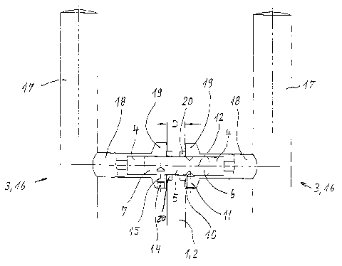
Figure 1 shows a view of a door handle arranged on both sides of a door leaf;
Figure 2 shows the pin by itself;
Figure 3 shows a section III-III according to Figure 2.
As is shown in Figure 1, two door handles 3 which are identically constructed
push
handles I6 in the embodiment example are arranged on both sides of a door leaf
1 formed
as a glass pane 2. Each push handle 16 comprises a handle 17 and a brace 18
formed

CA 02512888 2005-07-07
-4-
integral therewith. The braces 18 each have a pocket bore 4 in which a pin 8
is inserted
so as to penetrate the glass pane 2 by its middle portion 5. The thickness of
the glass pane
2 is designated by D in the present case.
As can be seen particularly from Figure 2, the pin 8 leas a first end portion
6 and a
second end portion 7. A circumferential groove 9 is provided in the area of
the end
portion 6, while three drill holes 13 are arranged in en3 portion 7 so as to
be offset,
respectively, by 120° in circumferential direction A (see Figure 3). As
is further shown in
Figure 2, the drill holes 13 are offset relative to one another in direction
of the
longitudinal axis 12 of the pin 8 in addition.
According to Figure 1, the braces 18 have diametral enlargements 19 in the
area of
contact with the glass pane 2. Transverse bore holes 10 and 14 which receive
threaded
screws 11 and 15 are introduced in these diametral enlargements 19. It can be
seen that
the threaded screw 11 engages in the circumferential groove 9, while the
threaded screw
can be screwed into one of the drill holes 13 so as to adapt to different
thicknesses D
15 of the glass pane 2. In the present case, a flexible glass protector 20 is
embedded in the
glass pane 2 on both sides, which ensures a reliable contact of the braces 18
at the glass
pane 2.

CA 02512888 2005-07-07
-5-
Reference Numbers
1 door leaf
2 glass pane
3 door handle
4 pocket hole
middle portion
6 end portion
7 end portion
8 pin
9 circumferential
groove
10transverse bore
hole
11threaded screw
12longitudinal axis
13drill holes
14transverse bore
hole
15threaded screw
16push handle
17handle
18brace
19diametral enlargement
20glass protector
A arrow direction
D thickness

Dessin représentatif
Une figure unique qui représente un dessin illustrant l'invention.
États administratifs

2024-08-01 : Dans le cadre de la transition vers les Brevets de nouvelle génération (BNG), la base de données sur les brevets canadiens (BDBC) contient désormais un Historique d'événement plus détaillé, qui reproduit le Journal des événements de notre nouvelle solution interne.

Veuillez noter que les événements débutant par « Inactive : » se réfèrent à des événements qui ne sont plus utilisés dans notre nouvelle solution interne.

Pour une meilleure compréhension de l'état de la demande ou brevet qui figure sur cette page, la rubrique Mise en garde , et les descriptions de Brevet , Historique d'événement , Taxes périodiques et Historique des paiements devraient être consultées.

Historique d'événement

Description Date
Demande non rétablie avant l'échéance 2007-08-17
Le délai pour l'annulation est expiré 2007-08-17
Réputée abandonnée - omission de répondre à un avis sur les taxes pour le maintien en état 2006-08-17
Inactive : CIB de MCD 2006-03-12
Inactive : Page couverture publiée 2005-09-27
Lettre envoyée 2005-09-23
Exigences relatives à une correction du demandeur - jugée conforme 2005-09-23
Inactive : Notice - Entrée phase nat. - Pas de RE 2005-09-23
Demande reçue - PCT 2005-09-01
Exigences pour l'entrée dans la phase nationale - jugée conforme 2005-07-07
Demande publiée (accessible au public) 2005-03-31

Historique d'abandonnement

Date d'abandonnement Raison Date de rétablissement
2006-08-17

Historique des taxes

Type de taxes Anniversaire Échéance Date payée
Taxe nationale de base - générale 2005-07-07
Enregistrement d'un document 2005-07-07
Titulaires au dossier

Les titulaires actuels et antérieures au dossier sont affichés en ordre alphabétique.

Titulaires actuels au dossier
DORMA GMBH + CO. KG
Titulaires antérieures au dossier
RALF KREYENBORG
Les propriétaires antérieurs qui ne figurent pas dans la liste des « Propriétaires au dossier » apparaîtront dans d'autres documents au dossier.
Documents

Pour visionner les fichiers sélectionnés, entrer le code reCAPTCHA :


Pour visualiser une image, cliquer sur un lien dans la colonne description du document. Pour télécharger l'image (les images), cliquer l'une ou plusieurs cases à cocher dans la première colonne et ensuite cliquer sur le bouton "Télécharger sélection en format PDF (archive Zip)" ou le bouton "Télécharger sélection (en un fichier PDF fusionné)".

Liste des documents de brevet publiés et non publiés sur la BDBC .

Si vous avez des difficultés à accéder au contenu, veuillez communiquer avec le Centre de services à la clientèle au 1-866-997-1936, ou envoyer un courriel au Centre de service à la clientèle de l'OPIC.


Description du
Document 
Date
(aaaa-mm-jj) 
Nombre de pages   Taille de l'image (Ko) 
Dessin représentatif 2005-07-06 1 9
Description 2005-07-06 5 196
Revendications 2005-07-06 1 45
Dessins 2005-07-06 1 14
Abrégé 2005-07-06 1 13
Avis d'entree dans la phase nationale 2005-09-22 1 193
Courtoisie - Certificat d'enregistrement (document(s) connexe(s)) 2005-09-22 1 104
Rappel de taxe de maintien due 2006-04-18 1 112
Courtoisie - Lettre d'abandon (taxe de maintien en état) 2006-10-11 1 175
PCT 2005-07-06 4 148