Note: Descriptions are shown in the official language in which they were submitted.
CA 02513040 2005-07-22
1
IMPROVED DRIVE-THROUGH ORDER MANAGEMENT SYSTEM AND
METHOD
DESCRIPTION
CROSS-REFERENCE TO RELATED APPLICATIONS
[0001] Not applicable.
TECHNICAL FIELD
[0002] The invention generally relates to a system and method for product
order
management and more specifically to managing the work flow associated with
drive-through
lanes of a store.
BACKGROUND OF THE INVENTION
[0003] Drive-through service or curbside delivery is a common feature provided
by
businesses such as fast-food restaurants, banks, pharmacies and even coffee
shops. The
primary goal of such drive-through services is to provide a customer with fast
and convenient
service while increasing the number of customers that may be served than
through
conventional walk-in transactions.
[0004] Typically, a customer in a car approaches a microphone/speaker system
contained
in a menu board in a drive-through lane outside of a restaurant, bank,
pharmacy, or coffee
shop. The customer is prompted by an order-taker, through the speaker, to
place an order.
The customer dictates an order through the microphone. Generally, the order-
taker wears a
headset having a microphone and speaker to communicate with the customer
placing the
order. As the order is being placed or once the order has been taken, the
order-taker enters
the order information into a order management system. The order information is
displayed
on a display such that the order can be assembled by a runner.
[0005] One type of order management system displays customer order information
in one
of a plurality of positions sequenced from left to right acroSS the display.
As customer order
information is inputted, it is placed in any open position on the screen. Once
the order
appears in that position, it stays in the same position until the order is
removed from the
CA 02513040 2005-07-22
2
display, i.e., the order is delivered to the customer. In the event that there
is no open position,
the order information is placed in a memory queue. Once a position opens up,
the order
infonmation is placed in that position and will remain in that position until
it is removed from
the display, i.e., the order is delivered to the customer. The order
information includes a
colored header indicating the sequence that orders should be presented to the
respective
customer. These indicators change as orders are delivered to a customer and
the customer
product order information relating to that order is removed from the screen.
Such static
displays are difficult for presenters because they have to search the screen
to determine which
order is the next order to be presented as well as remember the priority of
the colored
headers.
[0006] In another type of order management system, the drive-through order
queue is
sequenced in a left-to-right format. As the first order is presented or
delivered to the
customer, it is bumped from the screen and the other orders shift to the left.
This type of left-
to-right display may reduce order accuracy and efficiency because the runner
is forced to
search the screen for the order they are filling while "filled" orders remain
on the screen. In
addition, there is no indication of the status of the order, such as whether
it has been
assembled, whether it is in the process of being assembled, or whether it
needs to be or has
been modified.
[0007] The present invention is provided to solve the problems discussed above
and other
problems, and to provide advantages and aspects not provided by prior systems
of this type.
A full discussion of the features and advantages of the present invention is
deferred to the
following detailed description, which proceeds with reference to the
accompanying drawings.
SUMMARY OF Tf~ INVENTION
[0008) The present invention relates to a drive-through product order
management
system. The system comprises a display and a processor. The display displays
first customer
product order information representative of a customer product order wherein
the first
customer product order information is positioned in a first position of the
display, 'The
processor correlates an indicator with the first customer product order
information. The
processor then positions the first customer product order information in a
second position of
the display.
CA 02513040 2005-07-22
(0009] The indicators are structured to indicate that the customer product
order is in the
process of being assembled, indicate that the customer product order has not
been assembled,
indicate that the customer product order was assembled, indicate that the
customer product
order was modified after the customer product order was assembled, indicate
the priority of
the customer product order, indicate a delay in delivering the customer
product order and/or
indicate that the first customer product order information has been positioned
in the second
position of the display.
[0010] The processor can receive a signal representative of a status change of
the
customer product order. In response, the processor can position the first
customer product
order information in the second position of the display, typically located to
the left of the first
position, or correlate another indicator with the first customer product order
information.
[0011) The present invention further includes a method for managing a drive-
through
product order management system. In one embodiment, the method includes
displaying a
first customer product order information representative of a customer product
order in a first
position of the display, correlating an indicator with the first customer
product order
information and then positioning the first customer product order information
in a second
position of the display. The method further includes a step of receiving a
signal
representative of a status change of the customer product order and
positioning the first
customer product order information area in the second position of the display
in response to
receiving the signal representing the status change.
[0012] In another embodiment, the method includes displaying a first customer
product
order information representative of a first customer product order wherein the
first customer
product order information is positioned in a first customer product order
first position of the
display and displaying a second customer product order information
representative of a
second customer product order wherein the second customer product order
information is
positioned in a second customer product order first position of the display.
The method
further includes the steps of correlating a first indicator with the first
customer product order
information and a second indicator with the second customer product order
information. The
method also includes the steps of removing the first customer product order
information and
displaying the second customer product order information in a second customer
product order
second position of the display. The second customer product order second
position may be
positioned to the left of the second customer product order first position.
The method further
CA 02513040 2005-07-22
includes rcmoving the sccond customer product order information from the
second customer
product order first position when the second customer information is
positioned in the second
customer product order second position.
[0013] In yet another embodiment, the method includes displaying a first
customer
product order information representative of a first customer product order in
a first position of
the display, receiving a second customer product order, and displaying a
second customer
product order information representative of the second customer product order
in a second
position of the display based on a placement criterion. Typically, the first
position is located
to the left of the second position of the display. The placement criterion
positions the first
customer product order information in the first position and places the second
customer
product order information in the second position based on at least one of a
time the second
customer product order was received and the availability of an open position
on the display.
Further, when an open position is unavailable, the second customer product
order information
is temporarily stored in a memory queue.
[0014] Other features and advantages of the invention will be apparent from
the
following specification taken in conjunction with the following drawings.
BRIEF DESCRIP'ITON OF THE DRAWINGS
To understand the present invention, it will now be described by way of
example, with
reference to the accompanying drawings in which:
FIG. 1 illustrates a high level view of an order management system for
managing
work flow associated with drive-through lanes of a store according to the
present invention;
FIG. 2 is a block diagram of a computer used in connection with the present
invention;
FIG. 3 illustrates a display of customer product order information according
to the
presentinvention;
FIG. 4A illustrates a display of customer product order information before a
runner
bump according to the prcsent invcntion;
CA 02513040 2005-07-22
FIG. 4B illustrates a display of customer product order information after a
runner
bump according to the present invention;
FIG. SA illustrates a display of customer product order information before a
presenter
bump according to the present invention;
FIG. 5B illusuates a display of customer product order information after a
presenter
bump according to the present invention;
FIG. 6A illustrates a display of customer product order information before
customer
product order information changes positions while the customer order is being
assembled
according to the present invention;
FIG. 6B illustrates a display of customer product order information after
customer
product order information changes positions while the customer order is being
assembled
according to the present invention;
FIG. 7A illustrates a display of customer product order information before
customer
product order information changes positions after the customer order has been
assembled
according to the present invention;
FIG. 7B illustrates a display of customer product order information after
customer
product order information changes positions after the customer order has been
assembled
according to the present invention;
FIG. 8A illustrates a display of customer product order information before a
customer
order is held according to the present invention;
FIG. 8B illustrates a display of customer product order information after a
customer
order is held according to the present invention;
FIG. 9A illustrates a display of customer product order information before a
customer
order is modified according to the present invention; and,
FIG. 9B illustrates a display of customer product order information after a
customer
order is modified according to the present invention.
CA 02513040 2005-07-22
6
DETAILED DESC1ZIPT10N
[0015] While this invention is susceptible of embodiments in many different
forms, there
are shown in the drawings and will herein be described in detail preferred
embodiments of
the invention with the understanding that the present disclosure is to be
considered as an
exemplification of the principles of the invention and is not intended to
limit the broad aspect
of the invention to the embodiments illustrated.
[0016] FIG. 1 illustrates a high level view of an order management system 10
for
managing the work flow associated with drive-through lanes of a store, such as
a fast food
restaurant or other store which sells food items or goods. The order
management system 10
can be part of a point of sale (POS) system, as known to one of ordinary skill
in the art, or
separate therefrom. The order management system 10 has a server 11 with drive-
through
management software 17 running thereon. Additional general information about
POS
systems can be found in U.S. Patent No. 3,946,220, U.S. Patent No. 5,128,862,
and U.S.
Patent No. 6,661,997 (and others), all of which are hereby incorporated by
reference. The
order management system 10 has one or more displays 13 for "runners" and
"presenters." In
the drive-through operation of the present invention, runners gather the items
for orders
placed in the drive-through lanes) and presenters present the orders taken
from cars which
have placed an order in the drive-through lane or lanes (multiple parallel
Innes). Once the
runner is done gathering an order, the presenter will present the order. The
presenter can also
receive payment if presentation and payment is performed at the same window.
The order
management system 10 allows for increased effciency through a clear interface
display of
the workflow process and th'e use of nonverbal communication.
[0017] The runners and presenters can wear or be near input devices 19 which
communicate with the server I I and the drive-through management software 17
causing
various actions to occur, as will be described herein. The input devices 19
can be in a non-
stationary position or a stationary position and have a wireless or wired
connection to the
order management system 10 running the drive-through management software 17.
Preferably, the input devices 19 carried by the runners are wireless input
devices and the
input devices 19 carried by the presenters are stationary input devices. There
may be
multiple input devices 19 for the runners, presenters and other crew
personnel. Also, the
presenter and the runner can use the same display 13 or have different
displays. Other
embodiments having multiple runners and/or presenters are possible as well.
CA 02513040 2005-07-22
[0018] Generally, in terms of hardware architecture, as shown in FIG. 2, the
server 11
includes a processor 12, memory 14, arid one or more input and/or output (I/O)
devices 16 (or
peripherals) that are communicatively coupled via a local interface 18. The
local interface 18
can be, but is not limited to, one or more buses or other wired or wireless
connections, as is
known in the art. The local interface 18 may have additional elements, which
are omitted for
simplicity, such as controllers, buffers (caches), drivers, repeaters, and
receivers, to enable
communications. Further, the local interface 18 may include address, control,
and/or data
connections to enable appropriate communications among the aforementioned
components.
[0019] The processor 12 is a hardware device for executing software,
particularly that
stored in the memory 14. The processor 12 can be any custom-made or
commercially
available processor, a central processing unit (CPU), an auxiliary processor
among several
processors associated with the server 1 l, a semiconductor-based
microprocessor (in the form
of a microchip or chip set), a macroptocessor, or generally any device for
executing software
instructions. Examples of suitable commercially available microprocessors are
as follows: a
PA-RISC series microprocessor from Hewlett-Packard Company, an 80x86 or
Pentium series
microprocessor from Intel Corporation, a PowerPC microprocessor from ISM, a
Spare
microprocessor from Sun Microsystems, Ine, or a 68xxx series microprocessor
from
Motorola Corporation.
[0020] The memory 14 can include any one or a combination of volatile memory
elements (e.g., random access memory (RAM, such as DRAM, SRAM, SDRAM, etc.))
and
nonvolatile memory elements (e.g., ROM, hard drive, tape, CDROM, etc.).
Moreover, the
memory 14 may incorporate electronic, magnetic, optical, and/or other types of
storage
media. Note that the memory 14 can have a distributed architecture, where
various
components are situated remote from one another, but can be accessed by the
processor 12.
[0021] The software 17 in the memory 14 may include one or more separate
programs,
each of which has an ordered listing of executable instructions for
implementing logical
functions. In the example of FIG. 2, the software 17 in the memory 14 includes
the order
management system 10 in accordance with the present invention and a suitable
operating
system (O/S). A non-exhaustive list of examples of suitable commercially
available
operating systems is as follows: (a) a Windows operating system available from
Microsoft
Corporation; (b) a Netware operating system available from Novell, Inc.; (c) a
Macintosh
operating system available from Apple Computer, Inc.; (d) a UNIX operating
system, which
CA 02513040 2005-07-22
is available for purchase from many vendors, such as the Hewlett-Packard
Company, Sun
Microsystems, Ine., and AT&T Corporation; (e) a LINUX operating system, which
is
freeware that is readily available on the Intcrnct; (f) a run time Vxworks
operating system
from WindRiver Systems, Inc.; or (g) an appliance-based operating system, such
as that
implemented in handheld computers or personal data assistants (PDAs) (e.g.,
PaImOS
available from Palm Computing, Inc., and Windows CE available from Microsoft
Corporation). The operating system essentially controls the execution of other
computer
programs, such as the order management system 10, and provides scheduling,
input-output
control, file and data management, memory management, and communication
control and
related services.
[0022] The order management system 10 may be a source program, an executable
program (object code), script, or any other entity comprising a set of
instructions to be
performed. When the order management system 10 is a source program, the
program needs
to be translated via a compiler, assembler, interpreter, or the like, which
may or may not be
included within the memory 14, so as to operate properly in connection with
the O/S.
Furthermore, the order management system 10 can be written as (a) an object-
oriented
programming language, which has classes of data and methods, or (b) a
procedure
programming language, which has routines, subroutines, and/or functions, for
example, but
not limited to, C, C++, Pascal, Basic, Fortran, Cobol, Perl, Java, and Ada.
[0023] The I/O devices 16 may include input devices such as a keyboard, a
mouse, a
scanner, a microphone, etc. The I/O devices 16 may also include output devices
such as a
printer, the wireless devices 19, the display 13, etc. Finally, the 1/O
devices 16 may further
include devices that communicate both inputs and outputs, for instance, but
not limited to, a
modulator/demodulator (modem; for accessing another device, system, or
network), a radio
frequency (RFC or other transceiver, a telephonic interface, a bridge, a
router, etc. The 1/O
devices 16 can be any custom-made or commercially available 1/0 devices.
[0024] If the server 11 is a PC, workstation, or the like, the software in the
memory 14
may further include a basic input-output system (BIOS) (not shown). The BIOS
is a set of
essential software routines that initialize and test hardware at startup,
start the O/S, and
support the transfer of data among the hardware devices. The BIOS is stored in
ROM so that
the BIOS can be executed when the server 11 is activated.
CA 02513040 2005-07-22
9
[0025] When the server 11 is in operation, the processor 12 is configured to
execute
software stored within the memory 14, to communicate data to and from the
memory 14, and
to generally control operations of the server I1 pursuant to the software. The
order
management software 17 and the O/S 22, in whole or in part, but typically the
latter, are read
by the processor 12, perhaps buffered within the processor 12, and then
executed.
[0026) When the order management system 10 is implemented in software 17, as
shown
in FIG. 2, it should be noted that the order management system 10 can be
stored on any
computer-readable medium for use by, or in connection with, any computer-
related system or
method. A computer-readable medium is any electronic, magnetic, optical, or
other physical
device or means that can contain or store a computer program for use by, or in
connection
with, a computer-related system or method. The order management system 10 can
be
embodied in any computer-readable medium for use by, or in connection with, an
instruction
execution system, apparatus, or device, such as a computer-based system,
processor-
containing system, or other system that can fetch the instructions from the
instruction
execution system, apparatus, or device, and execute the instructions. A
computer-readable
medium can be any means that can store, communicate, propagate, or transport
the program
for use by, or in connection with, the instruction execution system,
apparatus, or device. For
example, the computer-readable medium can be an electronic, magnetic, optical,
electromagnetic, infrared, or semiconductor system, apparatus, device, or
propagation
medium. More specific examples (a non-exhaustive list) of computer-readable
medium
include the following: an electrical connection (electronic) having one or
more wires, a
portable computer diskette (magnetic), a random access memory (RAM)
(electronic), a read-
only memory (ROM) (electronic), an erasable programmable read-only memory
(EPROM,
EEPROM, or Flash memory) (electronic), an optical fiber (optical), and a
portable compact
disk read-only memory (CDROM) (optical).
[0027) In an alternative embodiment, where the order management system 10 is
implemented in hardware, the order management system 10 can utilize any one,
or a
combination of, the following technologies, which are each well known in the
art: a discrete
logic circuits) having logic gates for implementing logic functions upon data
signals, an
application-specific integrated circuit (ASIC) having appropriate
combinational logic gates, a
programmable gate arrays) (PGA), a field-programmable gate array (FPGA), etc.
CA 02513040 2005-07-22
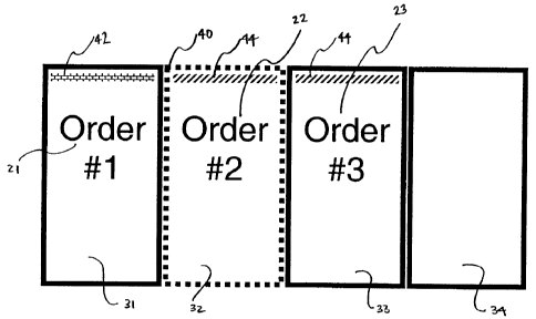
[0028] As noted above, one or more displays 13 are communicatively coupled to
the
server 11 via the local interface 18 for displaying customer product order
information 21, 22,
23, 24 representative of a customer order in a respective position 31, 32, 33,
34 of the display
13. As illustrated in FIG. 3, the customer product order information 21, 22,
23, 24 is
sequenced from left to right. Unpaid orders arc usually shown in the sequence
based on
when the orders are stored in the system. Paid orders are usually shown in the
sequence
based on when the orders are paid. Sequentially, paid orders will precede
unpaid orders.
This is true, regardless of the sequence the orders were started and
regardless of the order
number. Thus, in the display of FIG. 3, order #i 21 in the left position 31
was stored into the
order management system 10 prior to order #2 22 in the left-center position
32. Similarly,
order #2 22 was stored into the order management system 10 prior to order #3
23 in the right-
center position 33. Finally, order #3 23 was stored into the order management
system 10
prior to order #4 24 in the right position 34.
[0029] In the event that a new order is entered into the system and a position
is not
available, the customer product order information is stored in a memory queue
until a
position becomes available. Once a customer product order information, such as
order #1 21,
is removed from the screen and the other customer product order information is
shifted, a
position becomes available. The customer product order information previously
stored in the
memory queue is now displayed in the open position. Preferably, this open
position is the
right position 34.
[0030] Crew members, such as runners and presenters can take various actions
on orders
shown on the display(s). In one embodiment, the runner can indicate to the
system the
can ent order the runner is working on and select the next order in sequence
to attend to or
work on. This can be done as a part of a runner bump. As will be described
below, an
indicator on the display, which shows which order the runner is working on,
will move or
"bump" to another position. In another embodiment, the presenter can perform a
presentEr
bump to indicate that an order has been presented or delivered to the
customer. As will be
described below, the order which the presenter presented or delivered to the
customer will
"bump" or be removed from the display(s), and all other orders will shift left
on the
display(s). In yet another embodiment, the runner, presenter and/or other crew
members can
take action which indicates to the system that at least one customer product
order information
has switched positions on the display before or while they are being
assembled. In another
CA 02513040 2005-07-22
11
embodiment, the runner, presenter and/or ether crew members can take action
which
indicates to the system that at least one customer product order information
has switched
positions on the display after the runner has assembled the customer order. In
yet another
embodiment, the runner, presenter and/or other crew members can take action
which
indicates to the system that the current runner order should be "parked: '
Parking an order
indicates that store personnel should inform a customer to park their car and
the order will be
brought out to their car instead of delivering the food to them through the
drive-through
window. In another embodiment, the runner, presenter, and/or other crew
members can take
action which indicates to the system that the content of the customer product
order was
modified.
[0031] FIG. 4A and FIG. 4B illustrate a runner bump in the order management
system
10, showing the display 13 before the runner bump in FIG. 4A and the display
13 after the
runner bump in FIG. 4B. In FIG. 4A, order #1 21 is in the left position 31,
order #2 22 is in
the left-center position 32 and order #3 23 is in the right-center position
33. Indicator 40 is
correlated with order #2 22 indicating that the runner is currently working on
order #2 22.
Preferably, indicator 40 is a box surrounding the customer product order
information shown
on the display 13. Indicator 44 is also correlated with order #2 22 indicating
that order #2 22
has not been assembled yet. This same indicator 44 is correlated with order #3
23 indicating
that order #3 23 has not been assembled. Another indicator 42 is correlated
with order #1 21
indicating that the order has been assembled and is ready to he presented or
delivered to the
customer.
[0032] Once the runner has assembled the customer order, the runner inputs
this
information to the order management system 10 through the input device 19. In
response, the
order management system 10 performs a runner bump, resulting in the display
shown in FIG.
4B. Similar to FIG 4A, order #1 21 is in the left position 31, order #2 22 is
in the left-center
position 32 and order #3 23 is in the right-center position 33. However,
indicator 40 is now
correlated with order #3 23 indicating that the runner is working on order #3
23. Indicator 44
is still correlated with order #3 23 indicating that the order has not been
assembled. Finally,
indicators 42 are correlated with order #I 21 and order #2 22 indicating that
the orders have
been assembled and are ready to be presented or delivered to the respective
customer.
[0033] FIG. SA and FIG. SB illustrate a presenter bump in the order management
system
10, showing the display 13 before the presenter bump in FIC3. SA and the
display 13 after the
CA 02513040 2005-07-22
12
presenter bump in FIG. SB. In FIG. SA, order #1 21 is in the left position 31,
order #2 22 is
in the left-center position 32 and order #3 23 is in the right-center position
33. Indicator 40 is
correlated with order #3 23 indicating that the runner is currently working on
order #3 23.
Indicator 44 is also correlated with order #3 23 indicating that order #3 23
has not been
assembled yet. Another indicator 42 is correlated wish order #1 21 and order
#2 22 indicating
that the respective orders have been assembled and are ready to be presented
or delivered to
the respective customer.
[0034] Once the presenter presents or delivers the customer order represented
by order #1
21, the presenter inputs this information to the order management system 10
through the
input device 19. In response, the order management system 10 performs a
presenter bump,
resulting in the display shown in FIG. 5B. In FIG. 5B, order #121 has been
removed from
the display, and order #2 22 and order #3 23 have shifted one position to the
left on the
display 13. As a result, order #2 22 is displayed in the left position 31 and
order #3 23 is
displayed in the left-center position 22. Indicator 40 and indicator 44 are
still correlated with
order #3 23, respectively indicating that the runner is currently working on
the order and the
order has not been assembled yet. Further, indicator 42 is still correlated
with order #2 22
indicating that order #2 22 is ready to be presented or delivered to the
customer. Assuming
that the right position was filled before the presenter bump and new customer
product order
information is stored in the memory queue and is not being displayed, it will
now be
displayed in the next available position to the right.
[0035) FIG. 6A and FIG. 6B illustrate an embodiment in which customer product
order
information changes positions while a customer order is being assembled. An
order may
switch positions before it is assembled because it is of a higher priority
than another order
and needs to be assembled before another order. The order management system 10
determines whether an order is of a higher priority based on predetermined
criteria. For
example, an order maybe of a higher priority than another because it was paid
for before the
other order. FIG. 6A illustrates the display 13 before the order switches
positions and FIG
6B illustrates the display 13 after the order switches positions. In FIG. 6A,
order #1 21 is in
the left position 31, order #2 22 is in the left-center position 32, order #3
23 is in the right-
center position 33, and order #4 24 is in the right position 34. Indicators 42
are correlated
with order #121 and order #2 22 indicating that the respective orders are
ready to be
presented or delivered to the customer. Indicators 44 are correlated with
order #3 23 and
CA 02513040 2005-07-22
13
order #4 24 indicating that the respective orders have not been assembled yet.
Indicator 40 is
correlated with order #3 23 indicating that the runner is currently working on
order #3 23.
[0036] The order management system determines that a customer product order
information needs to switch positions based on a crew member action inputting
information
into the order management system 10 through the input device 19. In response,
the order
management system 10 switches the position of the customer product order
information that
needs to be switched. In FIG. 6B, order #3 23 and order #4 24 have switched
positions as
compared to FIG, 6A. As a result, order #3 23 in displayed in the right
position 34 and order
#4 24 is displayed in the right-center position 33. Indicators 44 are still
correlated with order
#3 23 and order #4 24 indicating that the respective orders have not been
assembled yet.
Further, indicator 40 is still correlated with order #3 23 indicating that the
runner is currently
working on order #3 23. In addition, indicator 46 is correlated with order #4
24 indicating
that the order is of a higher priority than the order currently being worked
on by the runner.
This is an indication that the runner is working on, or is set to work on, an
order which is not
of the highest priority.
[0037] FIG. 7A and FIG. 7B illustrate an embodiment in which customer product
order
information changes positions after a customer order has been assembled. An
order may
switch positions after it is assembled because it needs to be presented before
another order.
FIG. 7A illustrates the display 13 before the order switches positions and FIG
7B illustrates
the display 13 after the order switches positions. In FIG. 7A, order #1 21 is
in the left
position 31, order #2 22 is in the left-center position 32, order #3 23 is in
the right-center
position 33, and order #4 24 is in the right position 34. Indicators 42 are
correlated with
order #1 21, order #2 22 and order #3 23 indicating that the respective orders
are ready to be
presented or delivered to the customer. Indicator 44 is correlated with order
#4 24 indicating
that the order has not been assembled yet. Indicator 40 is also correlated
with order #4. 24
indicating that the runner is currently working on order #4 24.
[0038) The order management system 10 determines that a customer order needs
to
switch positions based on a crew member action inputting information to the
order
management system 10 through the input device 19. In response, the order
management
system 10 switches the position of the order that needs to be switched. In
FIG. 7B, order #2
22 and order #3 23 have switched positions as compared to FIG. 7A. As a
result, order #2 22
is displayed in the right-center position 33 and order #3 23 is displayed in
the left-center
CA 02513040 2005-07-22
14
position 32. Indicators 44 arc still correlated with order #1 21, order #2 22
and order #3 23
indicating that the respective orders have been assembled and are ready to be
presented or
delivered to the customer. Further, indicator 40 is still correlated with
order #4 24 indicating
that the runner is currently working on order #4 24. Additionally, indicator
44 is still
correlated with order #4 24 indicating that the order has not been assembled
yet. In addition,
indicator 48 is correlated with order #3 23 indicating that the order has been
moved up in the
sequence after the runner has completed assembling the order. Preferably,
indicator 48 is
flashing so as to easily draw attention to the display 13.
[0039] FIG. 8A and FIG. 8B illustrate an embodiment in which an order is not
complete
and the customer's car should be parked. A customer's car may need to be
parked because
the entire order, or a portion thereof, has not been assembled and must be
held until it is
assembled. FIG. SA ihustrates the display 13 before order #1 21 is held and
FIG. 8B
illustrates the display 13 after order #121 is held. In FIG. 8A, order #121 is
in the left
position 31, order #2 22 is in the left-center position 32, order #3 23 is in
the right-center
position 33, and order #4 24 is in the right position 34. Indicator 40 is
correlated with order
#1 21 indicating that the runner is currently working on the order. Further,
indicators 44 are
correlated with order #1 2I, order #2 22, order #3 23, and order #4 24
indicating that the
respective orders have not been assembled yet.
[0040] The order management system 10 determines that a customer order, such
as order
#1 21, needs be held based on a crew member action inputting information to
the order
management system 10 through the input device 19. In response, the order
management
system 10 indicates the order is being held and the customer's car should be
parked. In FIG.
8B, as compared to FIG. 8A, order #121 remains in the left position 31, order
#2 22 remains
in the left-center position 32, order #3 23 remains in the right-center
position 33, and order #4
24 remains in the right position 34. Indicator 44 and indicator 50 are
correlated with order #1
21 indicating that the order is not ready and needs to be held. Indicator 40
is now correlated
with order #2 22 indicating that the runner is currently working on order #2
22. Indicators 44
are still correlated with order #2 22, order #3 23 and order #4 24 indicating
that the orders
have not been assembled yet.
[0041] FIG. 9A and FIG. 9B illustrate an embodiment in which an order is
modified after
it has been assembled. FIG. 9A illustrates the display 13 before order #1 21
is modified and
FIG 9B illustrates the display 13 after the order #1 21 is modified. In FIG.
9A, order #1 21 is
CA 02513040 2005-07-22
1$
in the left position 31, order #2 22 is in the left-center position 32, order
#3 23 is in the right-
center position 33, and order #4 24 is in the right position 34. Indicator 40
is correlated with
order #3 23 indicating that the runner is currently working on the order.
Further, indicators
42 are correlated with order #1 21 and order #2 22 indicating that the
respective orders have
been assembled and are ready to be prcxnted or delivered to the customer.
Indicators 44 are
correlated with order #3 23 and order #4 24 indicating that the respective
orders have not
been assembled yet.
[0042] The order management system 10 determines that a customer order, such
as order
#1 21, needs to be modified based on a crew action inputting information to
the order
management system 10 through the input device 19. In response, the order
management
system 10 indicates the order is being modified. In FIG. 9B, as compared to
FIG. 9A, order
#1 21 remains in the left position 31, order #2 22 remains in the left-center
position 32, order
#3 23 remains in the right-center position 33, and order #4 24 remains in the
right position
34. Indicator 42 and indicator 46 are correlated with order #121 indicating
that the order has
been modified. Preferably, indicator 46 is flashing so as to easily draw
attention to the
display 13. Indicator 40 remains correlated with order #3 23 indicating that
the runner is
currently working on the order. Further, indicator 42 remains correlated with
order #2 22
indicating that the order has been assembled and is ready to be presented or
delivered to the
customer. Indicators 44 are still correlated with order #3 23 and order #4 24
indicating that
the respective orders have not been assembled yet.
[0043] While the specific embodiments have been illustrated and described,
numerous
modifications come to mind without significantly departing from the spirit of
the invention,
and the scope of protection is only limited by the scope of the accompanying
Claims.