Note: Descriptions are shown in the official language in which they were submitted.
CA 02513268 1999-12-21
METHOD OF MAKING A SKATE BOOT
FIELD OF THE INVENTION
The invention relates to a method of making a skate boot suitable for use on
ice skates and for use on in-line roller skates.
BACKGROUND OF THE INVENTION
1o Traditionally, shoes, boots or skate boots are fabricated by shaping the
footwear over a fast. A last is a three-dimensional shape of the inside cavity
of
a boot or shoe, and which may be mounted upside down for ease of
manipulation and assembly of the components making up the footwear. A pre-
assembled fabric component is positioned over the last to be formed to the
shape of the desire finished product. The pre-assembled component consists
of various layers of fabric andlor leather material sewn and/or glued
together,
and sometimes reinforced with rigid components, which have the general
configuration of the finished product but have not yet been shaped to the
final
form of the footwear. The rigidity and flexibility characteristics of the
footwear
2o are achieved by interposing the various layers of materials having suitable
mechanical properties in specific regions of the pre-assembled component.
An insole is positioned on the top portion of the last, which represents the
inside bottom part of the footwear and the pre-assembled fabric component is
positioned over the fast. The fabric components are stretched over the last
and pushed over the insole to conform to the specific shape of the last and
then nailed or tacked, and glued to the insole to maintain the desired shape.
Once the upper part of the footwear is completed, an outsole is glued over the
preliminary assembly to finish the footwear. For skates, an accessory such as
an ice runner holder or an in-line roller chassis is mounted to the outsole to
3o complete the skate.
1
CA 02513268 1999-12-21
This type of process is extensively used in the shoemaking industry. It
generates a good product but it has many disadvantages. For instance, the
number of parts involved in the process can be staggering; a conventional ice
skate for hockey may have some eighty parts to be assembled and shaped
over the fast. As a consequence, the manufacturing process is lengthy and
complex. The nature of the assembly of part is inherently labor intensive and
slow as there are many manual tasks to be performed and many steps are
necessary to complete the footwear. The considerable number of elements to
be assembled entails an increased risk of errors, particularly in the
alignment
~ o of the various elements of the pre-assembled component. Also, the process
of
pushing and stretching the material over the last may not always provide a
good alignment of the pre-assembled component over the insole. The
accumulation of material between the insole and the outsole during the pulling
and stretching step creates variations of the distance between the two parts,
which are not desirable. The centering of the outsole with the formed pre-
assembled component of the footwear become more difficult. The number of
components involved in the process and the increased probability of
misalignment of the various components, contribute at increasing the number
of rejected shoes, boots or skates in the manufacturing process or at least,
2o decrease the quality of the overall production. This traditional process of
making footwear also requires several molds and cutting dies to produce all
the parts necessary for making the footwear.
In an effort to reduce the number of components of footwear and specifically
25 sports footwear like skiing and skating boot, these are increasingly made
of a
plastic molded shell and sometimes of a combination of a rigid with softer
fabric components. U.S. Patent 4,777,74'! discloses an article of footwear
such as a shoe or skate, which comprises a molded exterior lower shell and a
semi-rigid molded tongue portion to dose the footwear. U.S. Patent 4,509,276
so discloses a skate boot made of a lower exterior molded rigid plastic
portion
and intermediate and upper portions made of pliable material to allow forward
flexure and torsional flexibility in the ankle area. Finally U.S. Patent
5,339,544
2
' CA 02513268 2006-O1-05
discloses a footwear comprising a first component made of a single piece of
molded synthetic material having a rear upper portion which extend from an
insole, and a second component made of soft material having a front upper
portion and a lining. The two components are connected together with the
lining of the second component inserted inside the rear portion of the first
component.
These designs effectively reduce the number of components utilized in the
manufacturing process of a footwear or skate. However, the final product
issued from any of these methods of making footwear, whether a shoe, a
boot, or a skate, has the appearance of a plastic shell. Consumers are not
particularly fond of the plastic shell look for footwear and show a preference
to
fabric or leather footwear product.
Thus there is a need in the industry for a method of making a skate boot that
controls the end shape and volume of the boot and also utilizes fewer
components and fewer steps than the traditional lasting method.
STATEMENT OF THE INVENTION
The invention provides a method of making a skate boot comprising: (a)
providing a structural inner shell for supporting a foot, the inner shell
having a
sole, heel counter and lateral and medial quarters projecting upwardly from
respective sides of said sole, and a toe box, the inner shell being shaped to
generally conform to the foot; (b) cutting a skin from a flat piece of fabric
or
leather material; (c) positioning the skin on an exterior surface of the inner
shell; (d) affixing the skin to the inner shell by applying pressure on the
skin;
and (e) mounting a tongue to the toe box for covering a front portion of the
skate boot. If the inner shell does not comprise an integrated toe box, the
3o method may further comprise mounting a toe box to the inner shell. An ice
runner and runner holder assembly or an in-line roller chassis may be
mounted to the bottom portion of the inner shell of the skate boot.
3
CA 02513268 2005-10-26
Other objects and features of the invention will become apparent by reference
to the following description and the drawings.
BRIEF DESCRIPTION OF THE DRAWINGS
A detailed description of the embodiments of the present invention is provided
herein below, by way of example only, with reference to the accompanying
drawings, in which:
1o Figure 1 is a top plan view of a skin for a footwear constructed according
to
the invention;
Figure 2 is a top plan view of the skin shown in Figure 1 with some decorative
components added;
Figure 3 is a top plan view of a second embodiment of a skin for the footwear
constructed according to the invention;
Figure 4 is a top plan view of the skin shown in Figure 3 with some decorative
2o components added;
Figure 5 is a perspective view of a skin assembly for the footwear constructed
according to the invention;
Figure 6 is a perspective view of an inner shell of the footwear constructed
according to the invention;
Figure 7 is a perspective view illustrating the assembly of the skin assembly
and the inner shell of the footwear constructed according to the invention;
-4-
CA 02513268 2005-10-26
Figure 8 is a perspective view illustrating the application of pressure to the
surface of the skin assembly and the inner shell according to the invention;
Figure 9 is a perspective view of an apparatus used to apply pressure to a
skin assembly as depicted in Figure 8 according to the invention;
Figure 10 is a perspective view of a completed boot constructed according to
the invention;
Figure 11 is a perspective view of a second embodiment of a skin assembly
for the footwear constructed according to the invention;
Figure 12 is a perspective view of a second embodiment of an inner shell of a
footwear constructed according to the invention;
Figure 13 is a perspective view of the assembly of the skin assembly and the
inner shell shown in Figures 11 and 12;
2o Figure 14 is a perspective view of the application of pressure to the
surface of
the skin assembly and the inner shell shown in Figures 11 and 12 of a
footwear constructed according to the invention;
Figure 15 is a perspective view of a second embodiment of a footwear
constructed according to of the invention; and
Figure 16 is a perspective view of a third embodiment of an inner shell of a
footwear constructed according to the invention;
3o In the drawings, embodiments of the invention are illustrated by way of
examples. It is to be expressly understood that the description and drawings
-5-
CA 02513268 1999-12-21
are only for the purpose of illustration and are an aid for understanding.
They
are not intended to be a definition of the limits of the invention.
DETAILED DESCRIPTION OF THE EMBODIMENTS
Figure 1 illustrates a skin 20, which has been cut from a flat piece of fabric
material or feather material. The cutting operation of skin 20 may be fully
automated since it is performed on a flat surface. Skin 20 may comprise a
right quarter 22 and a left quarter 24 linked together by a bridge portion 26.
Each quarter 22 and 24 may further comprise half-tendon guards 23 and 25
respectively. The heel portions 42 and 43 of each quarter 22 and 24 is given a
slightly curvilinear profile to enable the formation of a rounded heel counter
later on in the fabrication process of the footwear. Heel portions 42 and 43
are
also provided with indentations 45 to ease the formation of a rounded heel
counter.
Figure 2 illustrates a skin 20 to which decorative components 31 and 32 were
added. Decorative components 31 and 32 are assembled to skin 20 by
automated process such as automatic stitching or welding. The automation of
2o this process is again simplified because it is done on a flat surface.
Components 32 may be stitched, welded or glued to components 31 in a first
step then the assembly of components 31 and 32 may be assembled to skin
in a final step. Of course, the assembly of the various decorative
components may be performed in any order to adapt to the specific physical
requirements of available manufacturing equipment. It can also be done all at
once. The flexibility of fabrication of the skin assembly is due primarily to
the
fact that all the operations, including the cutting of skin 20, are performed
white the fabric material is laying down flat. Figure 2 illustrates the
decorative
components 31 and 32 stitched to skin 20 as shown by the stitching lines 33
3o and 34 by way of example only. Decorative components 31 and 32 could be
welded or glued or otherwise affixed to skin 20 in any known fashion without
departing from the principle of assembling as many if not al! skin components
6
CA 02513268 1999-12-21
while the various pieces are flat and therefore easy to work. The process is
thereby simplified and can readily be automated.
Figures 3 and 4 illustrate a variation of a skin 20. The right quarter 22 and
the
left quarter 24 are, in this case, linked together at tendon guard 37, which
is
the equivalent of the assembly of half-tendon guard 23 and 25, and at the rear
portions 38 and 39 of each quarter 22 and 24. Half-bridge portions 26A and
26B are provided at the lower part of each quarter 22 and 24, to be used later
on to form the skin assembly of the footwear. In this variation the heel
portions
42 and 43 are separated by a cut-out portion 46 which has curvilinear walls to
enable the formation of a rounded heel counter as previously mentioned when
referring to slightly curvilinear profile of heel portions 42 and 43 shown in
Figures 1 and 2. Heel portions 42 and 43 are also provided with indentations
45 to facilitate the formation of a rounded heel counter.
Figures 3 and 4 illustrate each quarter 22 and 24 having a similar profile to
quarters 22 and 24 of skin 20 shown in Figures 1 and 2. Figure 3 illustrates a
skin 20 made from a single flat piece of fabric or leather material whereas
Figure 4 illustrates a skin 20 with decorative components 31 and 32 added in
2o the same fashion as previously described in Figure 2.
The skin 20 is cut, as its profile indicates, to conform to the general shape
of a
boot. Skin 20 may have a variety of shapes and profiles to conform to the
external surface of the footwear and/or different types of footwear. For
example, a low-cut boot woutd not feature a tendon guard 37 and its skin
would be designed without one. Similarly, a shoe type footwear as shown in
Figures 11 to 15 features a skin 20 which is very low and barely reaches the
foot's malleollis. Shown in dotted fines is a variation of a footwear having
higher sides which cover the foot's malleollis.
The skin 20 shown in Figure 2 will be used as an example to illustrate the
process of making a footwear according to the invention. It is understood that
CA 02513268 2005-10-26
types of skin configuration and pattern could be used for covering the
footwear. As a further variation of skin 20, quarters 22 and 24 may be two
single pieces joined together by a third piece covering bridge portion 26.
Referring now to Figure 5, the flat skin 20 has been folded at the bridge
portion 26 and sewn at the rear edges of cuff portions 23 and 25 and at heel
portions 42 and 43 to form a skin assembly 30. The resulting seem 44 may be
covered by an additional decorative piece if desired (not shown). As
previously mentioned, when both heel portions 42 and 43 are sewn together,
they form a rounded heel counter 48 which better conforms to the contours of
the foot. Indentations 45 are also folded to form a round edge at the bottom
portion of heel counter 48.
The skin assembly 30, once formed, preferably has openings 49 and 50 in its
~5 bottom portion, which provide direct access to the internal structure of
the
footwear.
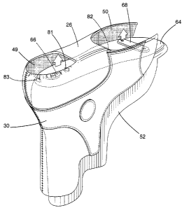
Figure 6 illustrates an inner shell 52 having the general outer shape of a
boot.
Inner shell 52 may be made of injected thermoplastic. It comprises a heel
2o counter 58 and a tendon guard 60, a medial quarter 54 and a lateral quarter
56 of variable thickness extending longitudinally from heel counter 58 to the
front of inner shell 52. Quarters 54 and 56 each have an edge 63, which
together define the main opening for insertion and removal of the foot. A sole
64 extends the entire length of inner shell 52. Inner shell 52 is the central
25 component of the footwear to be constructed. It is shaped to conform
generally to the shape of the foot and the shape given to inner shell 52
thereby dictates the general shape of the footwear. Inner shell 52 further
provides the supporting structural element of the footwear. Inner shell 52 may
be made and manufactured by injection molding such that variation of its wall
3o thickness is easily achieved. By strategically varying its wall's
thickness, inner
shell 52 may be provided with areas, which are more or less rigid and more or
less flexible, as desired, depending on the purpose of the final product. For
_g_
CA 02513268 1999-12-21
instance, an ice skate molded inner shell would have to have more overall
rigidity than shoes for football or plain running shoes.
Variations of the materials employed or combining two or more materials are
other methods of changing and varying the physical properties of the inner
shelf 52 and therefore of the final footwear so constructed. Compatible
materials may be manufactured by successive injections into the same mold.
For example, the inner shell 52 may be molded with two materials: a more
rigid material in areas where more support is necessary combined with a
1o softer material in areas requiring more flexibility. Also, in the area
corresponding generally to edges 63 where the face eyelets will eventually be
positioned, a slightly more resilient material may be used or the thickness of
the material can be marginally increased in an effort to reinforce this
locally
solicited area.
Sole 64 may be substantially flat or it may comprise, as shown in Figure 6,
bottom projections 66 and 68 as means for attachment- to a ground engaging
supporting element such as an ice runner or an in-line roller chassis.
Projection 66 and 68 are designed to mate the opposing surface of the
2o ground-engaging supporting element. This arrangement is shown as an
example only since there are many possible variations. Sole 64 also
comprises positioning pins 81, 82 and 83 adapted to align skin assembly 30
with inner shell 52.
The frontal portion of the inner shell 52 in the toe area 71 is open. Although
not necessary, it allows the installation of a toebox/tongue assembly as shown
in Figure 10. As a variation, the inner shell 52 could easily be closed at the
toe
area 71 so that the toe box would be integral with inner shell 52.
3o The configuration of the inner shell 52 and its inherent rigidity
eliminates the
need to use a fast to shape the skin assembly 30. As shown in Figures 7 and
8, skin assembly 30 is positioned over the inner shell 52. The general shape
9
CA 02513268 1999-12-21
of skin assembly 30 ensures a good alignment between the two components.
The alignment of openings 49 and 50 of skin assembly 30 with positioning
pins 81, 82 and 83 provides increased accuracy of alignment. As best shown
in Figure 8, positioning pins 81, 82 and 83 correspond to the outer edges of
openings 49 and 50 thereby ensuring proper alignment of the two
components. Other means of alignment are possible without the use of
opening 49 and 50. Other positioning pins (not shown) could be added to
inner shelf 52, which could be inserted into corresponding apertures of skin
assembly 30 to align the two components 30 and 52. It must be understood
1o that the skin assembly 30 may or may not conform to the inner shell 52. As
a
variant, skin assembly may cover only partially the external surface of the
inner shell 52 leaving portions of the inner shell 52 exposed, giving the
footwear a different look.
Prior to positioning the skin assembly 30 over the inner shell 52, glue can be
applied either to the interior surface of skin assembly 30 or the exterior
surface of inner shell 52. Once skin assembly 30 is in place, pressure is
applied to the surface of the skin assembly 30 as depicted by arrows 70A and
70B thereby solidly affixing the two components together. The skin assembly
30 will conform exactly to the shape of inner shell 52 without the use of a
form
or last. The only rigid shape required for the process is the inner shell 52
itself.
Figure 9 illustrates an example of an apparatus 100, which may be used to
evenly apply pressure to the entire surface of skin assembly 30. Other means
of applying even pressure to skin assembly 30 are possible without departing
from the basic method hereby described. The clamping apparatus 100 shown
in Figure 9, comprises a supporting frame 102 having an upper traverse 103,
and two pillars 105 and 106 joined together at mid-height by an apron 104.
3o Control buttons are usually positioned on apron 104 for ease of access.
Apron
104 surrounds a movable shell-supporting member 108 is having the general
shape of an inner shell 52 and is mounted to a generally vertical hydraulic or
CA 02513268 1999-12-21
pneumatic piston-cylinder 110. A pair of clamps 112 and 113 are mounted to
traverse 103 with struts 115 and are positioned directly above shell-
supporting
member 108. Clamps 112 and 113, each are provided with a bladder
consisting of an inflated flexible membrane and a fluid pressure delivery
circuit
(not shown). A pressure pad 120 having a general shape which substantially
mates with the sole portion and the rear portion of inner shell 52 is located
in
between clamps '112, 113 at the top portion of the clamping pair.
In operation, the assembly of inner shell 52 and skin assembly 30 are
1o positioned on shell-supporting member 108 and the operator activates the
apparatus 100. The cycle of apparatus 100 begins with the activation and
extension of piston-cylinder 110, which raises shell-supporting member 108
and therefore, inner shell 52 and skin assembly 30 upwardly, as shown with
30 arrow "A", in between the open pair of damps 112, 113. Shell-supporting
member 108 travels up and reaches pressure pad 120, at which point
pressure builds up into piston-cylinder 110 to a set value and stops. The
mating surface of pressure pad 120 and shell-supporting member 108 thereby
apply the initial pressure 70A to the sole portion and the rear portion of
skin
assembly 30 onto inner shelf 52. Clamps 112 and 113 are then closed onto
2o inner shell 52 and skin assembly 30 as shown with arrows "B". With clamps
112, 113 closed and locked over the assembly, bladders are inflated by air or
liquid injection, which forces the flexible membranes of bladders to encircle
each quarter 22 and 24 of skin assembly 30 and apply pressure 70B of Figure
8. Pressure builds up inside inflated bladders to a set value and the flexible
membranes apply an even pressure 70B to each quarter surface of skin
assembly 30. The pressure is maintained for a few seconds and then
released. Clamps 112 and 113 open up and shell-supporting member 108 is
lowered to its initial position by piston-cylinder 110 retracting. The two
initial
components 30 and 52 are properly glued and can be removed from shell
3o supporting member 108.
11
CA 02513268 1999-12-21
To provide good adhesion between skin assembly 30 and inner shell 52 using
damping apparatus 100, a pressure build-up of about 30PS1 is contemplated.
Such a pressure requires that inner shell 52 be properly supported by shell-
supporting member 108 during the application of the pressure. To that effect,
shell-supporting members 108 of different sizes are provided for each
footwear sizes being produced. This ensures that inner shell 52 will not
collapse or distort during the application of a pressure of this magnitude.
However, a much lower pressure can be used which will provide adequate
adhesion. The pressure required for providing good adhesion between skin
1o assembly 30 and inner shell 52, is a function of the rigidity of the
material of
the skin assembly 30 and the complexity of the shape of the footwear. To
improve and accelerate the gluing process, shell-supporting member 108 may
be provided with heating and cooling channels (not shown). Depending on the
type of glue being used, the part may be heated and then cooled to increase
the efficiency of the process.
The manufacturing process is no longer a series of consecutive assembly
steps that occur over a last but is simply a joining together of two
prefabricated items manufactured separately using different methods. This
2o manufacturing process increases the possibilities of automation, as each
item
is fabricated separately and brought together at the end of the production
cycle. Furthermore, the fabrication of skin assembly 30 from a flat skin 20
reduces the possibilities of errors and likewise, the molding of inner shell
52 is
not conducive to errors. Once the mold is optimal, each part being produced
from the mold is unlikely to substantially vary. The joining of the two
components as previously explained only requires a minimal control of the
alignment of the two prefabricated parts. This modular approach of the
manufacturing process leads to a decrease in rejected items during
production, a better control of the end shape and volume of the footwear and
of course to a decrease in overall cost as production is rationalized.
12
CA 02513268 1999-12-21
As shown in Figure 10, lace eyelet holes 62 are punched along the edges 63
using a automatic punch which guides itself along edges 63 and rapidly
punches a series of eyelets 62 equally spaced apart. The following step is to
install a toe box 76 and a tongue 78 or, in the spirit of a modular approach,
a
toe-box/tongue assembly 79, which covers the frontal portion of the skate
boot 75. Toe-box/tongue assembly 79 is also manufactured separately and
brought to the production line at the end of the production cycle only. Tongue
78 is sewn or glued to toe-box 76. Toe-box 76 is glued to the upper fronts!
portion of sole 64 and can also be glued or sewn to the frontal portions 80 of
1o each quarter 22/56 and 24/54. A ground engaging supporting element such
as an ice runner holder or an in-line roller chassis is installed on the
bottom of
the inner shell 52 of the skate boot 75.
A suitable liner 51 is finally installed within the inner shell 52 of the
skate boot
75. The liner is preferably made of pre-formed foam material extending along
each quarter 54 and 56 and around the heel counter region. A footbed (not
shown) adapted to the contours of the foot may also be positioned at the
bottom of inner shell 52 to provide the required level of comfort to the skate
boot 75.
Figures 11 to 15 illustrate the various components and steps necessary to
fabricate a low-cut footwear according to the same basic method. Figure 11
shows a skin assembly 200, which has been folded, from a previously flat skin
and sewn at the rear edges of each quarter 203 and 204. A decorative
component 201 was assembled to the flat skin by automated process as
previously described. Skin assembly 200 presents a tow cut profile. The upper
edges 206 are much lower than skin assembly 30 shown in Figure 5 as it
extends nearly below the malleolis of the foot.
3o Figure 12 shows a molded inner shell 210 that may be made of injected
thermoplastic, which also presents a low-cut profile having the general outer
shape of a shoe. Inner shell 210 comprises a heel counter 212, a medial
13
CA 02513268 1999-12-21
quarter 214 and a lateral quarter 215 of variable thickness extending
longitudinally from heel counter 212 to the front portion of inner shell 210.
Edges 218 define the main opening for insertion and removal of the foot, and
a sole 220 extends the entire length of inner shell 210. Inner shell 210 is
the
central component of the shoe to be constructed. It is molded to generally
conform to the shape of the foot and its shape dictates the general shape of
the footwear. Inner shell 210 further provides the supporting structural
element of the footwear. As previously described, variations of the thickness
of the inner shell 210, variations of materials, or combination of two or more
o materials are methods of changing and adapting the physical properties of
inner shell 210 and of the footwear so constructed for its intended use.
It must be understood that the general outline of inner shell 210 may take on
a
variety of shapes such as that of a boot as depicted by the dotted lines 211.
~5 Skin assembly 200 may or may not conform to the boot outline 211. As a
variant, skin assembly may cover only partially the external surface of the
inner shell 210 leaving portions of the inner shell 210 exposed, giving the
footwear a different look. Boot outline 211 may be a hiking boot or a work
boot. In the later instance, a steel toe cap would be provided.
Sole 220 is substantially flat and adapted to accommodate a variety of
outsoles. The outsole of the footwear may feature spikes for football,
baseball
or soccer shoes or studs for golf or track and field shoes. Sole 220 may
feature apertures provided to insert metal or plastic studs or spikes.
As shown in Figures 13 and 14, skin assembly 200 is positioned over inner
shell 210 after a layer of glue has been applied to either the inner surface
of
skin assembly 200 or to the outer surface of inner shell 210 or both. The
general shape of skin assembly 200 ensures a good alignment between the
3o two components. The alignment accuracy may increase with positioning pins
as shown in Figure 6. Other means of alignment are also possible as
previously mentioned. Once skin assembly 200 is in place, pressure is applied
14
CA 02513268 1999-12-21
to the surface of skin assembly 200 as depicted by arrows 70A and 70B
thereby solidly gluing the two components together. A clamping apparatus
100 as shown in Figure 9 can be used to provide the necessary pressure. The
shell-supporting member 108 and the pressure pad 120 simply have to be
modified to accommodate the specific shape of inner shell 210.
As shown in Figures 15 and 16, lace eyelets 208 are punched info the
assembly of skin 200 and inner shell 220 along each edge 218. A toe box 230
and a tongue 231 or preferably, a toe-box/tongue assembly 232, which covers
~o the frontal portion of the footwear 250 are installed. Toe-bax,tongue
assembly
232 is of course, manufactured separately and brought to the production line
at the end of the production cycle only. Tongue 231 is sewn or glued to toe-
box 230. Toe-box 230 is glued to the upper frontal portion of sole 220 and can
also be glued or sewn to the frontal portions 235 of each quarter 203/214 and
204/215. Finally, a pair of outsoles 222 and 223, which are ground engaging
supporting elements, are affixed to the bottom of footwear 250. As shown in
Figure 16, a single outsole 225 extending the entire length of footwear 250
can be used as well.
2o The above description of embodiments should not be interpreted in a
limiting
manner since other variations, modifications and refinements are possible
within the spirit and scope of the present invention. The scope of the
invention
is defined in the appended claims and their equivalents.