Note: Descriptions are shown in the official language in which they were submitted.
CA 02513355 2005-07-14
WO 2004/067042 PCT/US2004/001056
TITLE OF THE INVENTION
COMPACTED IMPLANTABLE MEDICAL DEVICES AND
METHOD OF COMPACTING SUCH DEVICES
BACKGROUND OF THE INVENTION
1. Field of the I.nvention
The present invention relates to medical devices that are delivered into
patients by
catheters using minimally invasive procedures and methods of compacting such
devices.
2. Description of Related Art
Arteriosclerosis affects a significant portion of the population. The
progressive
nature of the disease can result in severe vessel stenosis (narrowing) and
ischemic
conditions distal to the stenosis. Although conventional surgical
interventions have proven
highly effective at treating such conditions, in many cases associated
procedural morbidity
and mortality has driven the development of alternate "minimally invasive"
therapies. These
therapies are particularly useful when a lesion to be treated is deep within
the body, such as
in aortic and cardiac vessels or within the skull base (such as, a carotid
artery or deep
neuro-vasculature). These minimally invasive techniques have enjoyed
increasing success
and acceptance in the treatment of several vascular diseases including
aneurysmal and
occlusive disease.
In a typical minimally invasive procedure, upon gaining percutaneous access to
the
patient's vascular system, a guidewire is introduced and guided under
fluoroscopic
visualization to the intended site of therapy. The guidewire then serves as
"rail" onto which
other subsequent devices are guided through the vessels to the site. A typical
occlusive
lesion may require pre-dilation (e.g., PTA or PTCA) and the placement of an
endovascular
device (such as a stent or stent-graft). This device may then permanently
reside within the
lumen of the vessel. All components for these procedures are delivered within
the vessel
(i.e., "endoluminally") and actuated remotely from outside of the body. Since
open surgery
is not required, these procedures are considered "minimally invasive."
For the purposes of the following description, endovascular devices may be
classified in two general categories: (1) plastically deformable (e.g.,
balloon expandable);
and (2) self-expanding.
1
CA 02513355 2005-07-14
WO 2004/067042 PCT/US2004/001056
Plastically deformable devices are generally deployed by deforming the device
at the
site of therapy,_usually, by internal pressure such as inflation of an
angioplasty balloon.
Devices of this type are generally made of a ductile bio-acceptable material
that provides
little recoil after dilation. A major advantage of the plastically deformable
device is obviating
the need for incorporating a restraining device into the delivery system since
balloon
inflation is all that is needed for proper deployment.
Self-expanding devices, in contrast, are designed to spontaneously deploy in
situ
once they are released from a constrained profile. They are generally made
from some type
of elastic, super-elastic, and/or shape memory metal or polymer. Advantages of
this type of
device are: 1) self-deployment obviates the need for high pressure ballooning
at the therapy
site; 2) clinical application of self-expanding devices has demonstrated a
significant increase
in minimum lumen diameter as compared to balloon expandable devices; and 3)
super-
elastic, pseudo-elastic, and shape memory alloys provide a high degree of
compliance and
will maintain their expanded profiles despite subsequent mechanical
deformation (such as
forces that might be encountered in an accident or other pressure applied
through a
patient's skin).
Both device categories share a common requirement that they must be introduced
to
the body from an access site remote to the actual therapy site. As a result,
they must be
inserted in a first small "introductory" configuration, guided at this
introductory profile through
a patient's vasculature, and deployed through an actuation mechanism to
achieve a second
"functional" configuration.
Many techniques have been developed to configure endovascular devices at a
small
introductory profile in preparation for insertion to the body. These
techniques vary
depending upon the category of the individual device.
In the instance of plastically deformable devices, the device may only need to
be
mechanically crimped onto a balloon prior to insertion to the body. Since this
device is
made of substantially non-recoiling material, the device, once crimped onto
the balloon, will
be readily retained on the balloon while being guided to the lesion site.
Although crimping may be done by hand, manual techniques are often
unsatisfactory
due to non-uniform pressure applied to the crimped device. This can lead to
non-uniform
device expansion and increased variability in clinical performance. As a
result, a number of
devices and processes have been developed to reliably and consistently crimp
plastically
deformable devices onto, or into, a delivery system.
US Patent 5,920,975 to Morales describes a tool that winds a spring-like
element
around a plastically deformable device while it is mounted upon a delivery
balloon. As the
spring is tightened, pressure is applied to the device intending to crimp it
onto the balloon.
2
CA 02513355 2005-07-14
WO 2004/067042 PCT/US2004/001056
EP Patent Application 630,623 to Williams et al. describes two methods to
reduce
the cross section of a device. In one embodiment, a plastically deformable
device is
mounted upon a delivery balloon and placed between reciprocating flat plates.
The flat
plates act to roll the device while reducing its cross sectional profile. The
additions of force
and size gauges, as well as inherent consistency of the machine, make this an
improvement
over the manual crimping technique of rolling the device between fingers.
In another embodiment of Williams et al., a plastically deformable device is
mounted
on a delivery balloon and then inserted into a chamber. This chamber is lined
with a sealed,
distensible bladder that, upon inflation, applies a circumferential crushing
force to the
device. This crushing force is intended to reduce the device profile and
securely mount the
device on the balloon.
US Patent 6,309,383 to Campbell et al. describes a crimping tool that
resembles a
hand-held nutcracker or set of pliers. A plastically deformable device is
mounted on a
delivery balloon and inserted into an orifice in the apparatus. The crimping
tool is squeezed
to apply pressure to the outside of the device to radially compact the device
onto the
balloon.
EP Patent Application 903,122 to Morales describes a crimping tool that uses a
set
of jaws to radially constrict a plastically deformable device onto a delivery
balloon. The
segmented jaws are hinged on one end to allow them to open and accept a device
and its
balloon delivery system. Once the device is inside, a collar is slid over the
outer surface of
the jaws. Pressure applied against the jaws by the collar causes them to
close, thereby
crushing'the device onto the balloon.
In the 'instance of self-expanding devices, the diametrical size of the device
needs to
be reduced to an "introductory" profile and held in place by some constraint.
This is
generally a more complex procedure than compacting a plastically deformable
device since
a steady constraint must be applied to the compacted device from its initial
compaction to its
ultimate deployment. This is typically accomplished using a tool or machine to
reduce the
device profile, and then the device is transferred in its compacted state to a
restraining
sheath, catheter, or other constraining means. The constraining means is kept
actively
engaged up to the time of deployment at the treatment site.
US Patent 6,096,027 to Layne describes an apparatus for crushing and loading a
self-expanding device. This device utilizes a bag surrounding the device that
is pulled
through a tapered die (funnel). As the device moves through the funnel its
cross sectional
profile is reduced. Upon exiting the die, the bag is removed and the device is
captured in a
restraining tube or sheath.
3
CA 02513355 2005-07-14
WO 2004/067042 PCT/US2004/001056
US Patent 5,928,258 to Kahn et al. describes an apparatus for crushing and
loading
a self-expanding device that utilizes a cylindrical cartridge for receiving
the device and
another implement for transferring the device into a delivery sheath. The
device is pulled
into the first cartridge, and then a plunger mechanism is used to transfer it
to an awaiting
delivery sheath or catheter.
US Patent 5,873,906 to Lau et al. describes a method of "folding" a self-
expanding
device which entails flattening and rolling the device into a "jelly roll"
configuration. The
device is then restrained in this "introductory" profile through the use of a
fiber based
constraining mechanism, and applied to a delivery system. A series of fibers
are likewise
used to constrain a self-expanding device in US Patent 6,224,627 to Armstrong
et al.
Further improvements in compacting self-expanding devices to a minimal
introductory profile are disclosed in International Publication No. WO
00/42948 to Vonesh et
al., which describes unique fluted funnel designs that allow self-expanding
devices to be
simultaneously folded and compacted through a funnel to a very low
introductory profile.
While all of these prior devices may work well for their intended purposes, it
is
believed that further significant reductions in introductory profiles may
still be possible. Two
competing design parameters confront an implantable device designer in
maximizing
compaction of a device. In addition to having sufficient structural integrity
to work for its
intended purpose, a compacted implantable device design must balance: (1) the
need to
limit the amount of niaterial comprising the implantable device so as to have
less material to
compact; and (2) the need to have a fairly robust implantable device that can
withstand the
considerable forces encountered in achieving extremely compact dimensions.
While a
device formed from thinner materials has less material to compact, such a
device may not
withstan'd the forces required to reach the smallest possible compacted state.
In contrast, a
robust implantable device that can be withstand aggressive "mashing" to
smaller dimensions
generally has too much material to achieve a small enough profile. This
conflict between
minimizing device bulk while maximizing device robustness is most clearly
confronted when
compacting a self-expanding implantable device through a funnel.
It is believed that the most effective means currently known for compacting a
self-
expanding device is to pull the device down to a compact size through one or
more funnel
devices, and particularly through a fluted funnel device. This process is very
effective at
achieving a small compacted size while imparting minimal damage to the
implantable
device. Unfortunately, the process of pulling a device through a funnel is
limited by the
robustness of the implantable device. In order to compact a device in a
funnel, the device is
attached to tether lines or similar means and then actuated through the
funnel. This applies
4
CA 02513355 2005-07-14
WO 2004/067042 PCT/US2004/001056
a number of forces to the implantable device, including the force necessary to
compact the
device as well as the friction forces applied by the funnel and any subsequent
restraining
means as the device is squeezed through these apparatuses. A thin, lightweight
device has
the advantage of having minimum material to compact, but such devices tend to
pull apart
as they are pulled through tight funnels to very small compacted dimensions.
More robust
devices that can withstand such extreme pulling forces can be provided, but
these devices
are by necessity bulkier and therefore limited in their ultimate
compactability.
It is accordingly a purpose of the present invention to provide an improved
method
for compacting an implantable device that can achieve a highly compacted
introductory
profile.
It is a further purpose of the present invention to provide such a method for
compacting that does not damage the device in the process of compaction and
without the
need to have an overly bulky implantable device.
It is still a further purpose of the present invention to provide an
implantable device
that has a very low delivery profile that is smaller than a profile that can
be achieved by
pulling the device through a funnel.
These and other purposes of the present invention will become evident from
review
of the following description.
SUMMARY OF THE INVENTION
The present invention provides unique implantable devices that have extremely
small
introductory profiles, and particularly interventional devices, and methods
for achieving such
small introductory profiles. The small profiles achieved with the present
invention are
possible by "decoupling" the forces required to pull an implantable device
through a funnel
into a retaining device from the forces required to compact the device fully
to its introductory
profile. For example, forces can be decoupled in the present invention by
pulling an
implantable device from a fully enlarged profile through a funnel and into a
capture tube at
an intermediate device profile. The intermediate profile should be one that
limits the
compaction and friction forces required to compact and capture the device to
less than the
longitudinal strength of the device. Once placed in the capture tube at the
intermediate
profile, the capture tube and device are then compressed further to a final
delivery profile by
swaging the capture tube.
The process of the present invention protects the integrity of the implantable
device
without requiring the implantable device to be more "robust" in order to
withstand the
5
CA 02513355 2005-07-14
WO 2004/067042 PCT/US2004/001056
cumulative compaction and friction forces of transforming it from its fully
enlarged profile to
its fully compacted profile. '
In one embodiment the present invention comprises a method of reducing the
cross
sectional dimension of a medical device by providing a medical device having
an initial cross
sectional profile and a restraining member adapted to receive the medical
device at a
reduced profile. The profile of the medical device is first reduced, such as
using a funnel or
similar reduction device, to an intermediate cross sectional profile and then
placed at this
intermediate profile into the restraining member. Radial compressive force is
then applied to
the restraining member to further reduce the cross sectional profile of the
medical device to
1'0 a fully compacted profile suitable for delivery into a patient.
The present invention further provides a self-expanding stent with an
extremely small
introductory profile. The stent is one having a longitudinal tensile strength,
an enlarged
diameter, and a compacted diameter. Since it is created through the de-
coupling process of
the present invention, the compacted diameter of said stent is smaller than a
diameter that
could be obtained using a funnel alone to reduce the stent from its enlarged
diameter to its
compacted diameter.
DESCRIPTION OF THE DRAWINGS
The operation of the present invention should become apparent from the
following
description when considered in conjunction with the accompanying drawings, in
which:
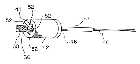
Figure 1 is a side view of an implantable device, in this instance a stent-
graft,
prepared for compaction in accordance with the present invention, tether lines
having been
applied to the device;
Figure 2 is a cross-section view of the implantable device along line 2-2 of
Figure 1
at an initial enlarged cross-sectional dimension;
Figure 3 is an isometric view of the device of Figure 1 being pulled through a
funnel
into a capture tube having an inner diameter (ID) approximately equal to an
intermediate
cross sectional dimension;
Figure 4 is a cross-section view of the funnel, device, and capture tube of
Figure 3,
with the device having been predominately compacted into the capture tube;
Figure 5 is an isometric view of the capture tube having the
implantable'device
contained therein;
Figure 6 is a cross-section view of the capture tube and device along line 6-6
of
Figure 5, showing the device at its intermediate cross sectional dimension;
6
CA 02513355 2005-07-14
WO 2004/067042 PCT/US2004/001056
Figure 7 is a schematic representation of a swaging die through which a
capture
tube and indwelling implantable device is compressed to a further reduced
dimension;
Figure 8 is a cross section view of the capture tube and indwelling
implantable
device being compressed by the swaging die of Figure 7, the implantable device
being
shown in partial cut-away through the capture tube;
Figure 9 is an isometric view of the capture tube having been compacted to a
final
cross sectional dimension with an indwelling implantable device;
Figure 10 is an enlarged sectional view of the capture tube of Figure 9,
showing the
compacted implantable device in partial cut-away;
Figure 11 is a cross-section view of the capture tube and device along line 11-
11 of
Figure 9, showing the device at its final reduced dimension;
Figure 12 is an isometric view of another embodiment of a capture tube of the
present invention including a pre-determined break zone therein;
Figure 13 is an enlarged partial isometric view of the capture tube of Figure
12,
showing the break zone;
Figure 14 is an enlarged side view of a capture tube having a break zone,
showing in
cut-away an indwelling implantable device and illustrating the break zone as a
further
enlarged insert;
Figure 15 is an isometric view of a capture tube having a break zone and an
indwelling compressed implantable device, the capture tube having been
compressed to
have an outer diameter (OD) approximately equal to a final compacted dimension
of the
implantable device, and a delivery sheath positioned over the capture tube,
the delivery
sh'eath having an inner diameter (ID) approximately equal to the outer
diameter of the
compressed capture tube;
Figure 16 is an isometric view of the capture tube and delivery sheath of
Figrue 15,
showing the capture tube having been separated at its break zone and each
resulting half of
the capture tube being removed from the sheath, leaving the implantable device
contained
at its final compacted dimension within the sheath;
Figure 17 is a side cross section view of an implantable device of the prior
art being
compacted through a funnel from an initial dimension to a final delivery
dimension within a
delivery tube having a dimension of "Z" and the forces F, and F2 (resulting in
overall force
F3) encountered in such compaction;
Figure 18 is a side partial cut-away view of the implantable device and
delivery tube
of Figure 17 showing force F2 encountered in deploying the device from the
delivery tube;
Figure 19 is a side cross section view of an implantable device of the present
invention being compacted through a funnel from an initial dimension to an
intermediate
7
CA 02513355 2005-07-14
WO 2004/067042 PCT/US2004/001056
dimension within a capture tube having a dimension of "X" and the forces Fl'
and F2'
(resulting in overall force F3') encountered in such compaction;
Figure 20 is a side cross section view of an implantable device and capture
tube of
Figure 19 being further compacted from dimension "X" to final dimension "Z" in
a swaging
die;
Figure 21 is a side partial cut-away view of the implantable device and
capture tube
of Figure 20 showing force F2 encountered in deploying the device from the
capture tube;
Figure 22 is a side cross section view of an implantable device of the present
invention being compacted through a funnel from an initial dimension to an
intermediate
dimension within a capture tube (including a break zone), having a dimension
of "X" and the
forces Fl' and F2' (resulting in overall force F3') encountered in such
compaction;
Figure 23 is a side cross section view of an implantable device and capture
tube of
Figure 22 being further compacted from dimension "X" to final dimension "Z" in
a swaging
die;
Figure 24 is a side partial cut-away view of the implantable device and
capture tube
of Figure 23 showing forces 1/2 F2 encountered in deploying the device from
the capture
tube that is separated at the break zone;
Figure 25 is an enlarged cross section view of an alternative swaging tapered
die for
use in the present invention, showing a capture tube and, in cut-away, a
indwelling
implantable device;
Figure 26 is a side view of an alternative compaction method of the present
invention
comprising an implantable medical device contained in a braided compaction
tube; and
Figure 27 is an isometric view of the implantable device and braided
compaction
tube of Figure 26 being drawn through a funnel into a capture tube.
DETAILED DESCRIPTION OF THE INVENTION
The present invention provides an improved method for compacting an
implantable
device to a very small introductory profile, and low-profile devices created
through such
method.
As the terms "interventional" or "minimally invasive" devices or procedures
are used
herein they are intended to encompass any device or procedure whereby a
medical
treatment implement is delivered to a treatment site by use of wires and/or
tubes threaded
through vessels or other body passageways accessed remotely. Minimally
invasive
implantable devices encompassed by the present invention may include those
employed in:
8
CA 02513355 2005-07-14
WO 2004/067042 PCT/US2004/001056
balloon angioplasty; thrombectomy; stent, graft, or stent-graft placement;
embolic filter
device placement; remote diagnostic procedures, such as those employing fiber
optic
cameras, ultrasound monitoring, MRI monitoring, x-ray monitoring, etc.; remote
therapeutic
procedures, such as those employing cutting blades, lasers, heat application,
cold
application, radiation, drug delivery, etc.; and any other similar devices or
procedures now
known or later developed. Currently such interventional procedures are
employed in large
and small blood vessels, in other vessels in the body, such as in the bile
duct, as well as in
the respiratory, digestive, reproductive, and other body systems. As the term
"patient" is
used herein it is intended to encompass both humans and animals.
The present invention achieves an extremely small introductory profile for
implantable devices by partially "decoupling" the forces required to pull an
implantable
through a funnel into a capture tube from the forces required to compact the
device fully to
its introductory profile. In its simplest form, the forces are decoupled by
pulling an
implantable device from a fully enlarged profile through a funnel and into a
capture tube at
an' intermediate device profile. The intermediate profile is chosen so that
the compaction
and friction forces required to compact the device and place it in the capture
tube are less
than the longitudinal strength of the device. In this manner the combined
forces required to
place the device into the capture tube are less than the longitudinal strength
of the device so
as to avoid any device damage in the initial pull down step. Once placed in
the capture tube
at the intermediate profile, the capture tube and device are then compressed
down to a final
delivery profile by swaging the capture tube. Far greater compaction is
possible using this
process without applying any excessive longitudinal strain on the implantable
device.
Overall, this process separates into multiple steps the forces required to
achieve full
compaction. The process protects the integrity of the implantable device
without requiring
the implantable device to be more "robust" in order to withstand the
cumulative compaction
and friction forces of transforming it from its fully enlarged profile to its
fully compacted
profile. In fact, the present invention can provide an implantable device at
an introductory
profile that it physically cannot achieve through compaction through a funnel
alone.
Further decoupling of forces in the present invention can be provided by using
a
capture tube having one or more break zones therein. The capture tube can be
split along
the break zones into discrete capture tube segments that can each be
separately removed
from the device. Frictional forces applied to the implantable device during
capture tube
removal can thus be further reduced.
9
CA 02513355 2008-02-01
Referring now to the drawings, Figures 1 through 11 illustrate process steps
of
practicing one embodiment of the present invention, compacting an implantable
device 30
from a fully enla'rged deployed profile 32 to a fully compacted introductory
profile 34. The
terrn "profil6 as it is used herein it is intended to encompass the overa(I
general dimensions
of an implantable device as viewed in cross section. "Profile" in the context
of the present
invention refers to the diameter of a device with circuiar cross-secfion as
well as dimensions
of implantable devices having oblong, triangular, rectangular, or other
regular or irregular
cross=sectional shapes.
Figures 1 and 2 show an implantable device 30 of the present invention. In
this
'10 instance; the implantable device comprises an implantable endoprosthesis
having a stent 36
and a gYaft 38 component attached together. Endoprostheses of similar forms
are
co'mmercially available from a number of sources. The endoprosthesis shown is
illustrative
of a variety of forms available from W. L. Gore & Associates, Inc., such as
the VIABAHNTM
tracheal eridoprosthesis and the HEMOBAHNTM' peripheral vascular
endoprosthesis.
`I5 In order to compact this device through a funnel, tether lines 40 can be
attached to
.one etid of the implantable device 30, as is shown in Figure 1. As is shown
in Figures 3 and
4, a furinel 42 is provided that has a wide opening 44 at one end-
approximately equal to the
fuily enlarged profile 32 and a narrow opening 46 at an opposite end
approximately equal to
an'interrimediate device profle 48. A restraining riiember or capture tube 50
is aligned with
20 the narrow operiing 46. The tether lines 40 are threaded through the funnel
42 and the
capture tub'e 50 and the itinplantable device 30 is then pulled down into the
capture tube, as
is shbwn in Figures 3 and 4. Once the implantable device 30 is fully pulled
within the
-captWre tube, the tether lines 40 can be removed. Figures 5 and 6 illustrate
the implantable
device 30 fully indvirelling withih the capture tube 50 at the intermediate
profile 48.
25 A preferred funnel 42 for use with the present invention has one or more
longitudinal
ribs or "flutes" 52 provided therein. Such flutes 52 can aid in the folding
and compacting of
the stent 36 elements as the device 30 is pulled through the funnel, as is
taught in
International Publication No. WO 00/42948 to Vonesh et al. (based on PCT
Applicabon
PCT/USOO/01557). It has been found that the orderly folding of
30, the endoprosthesis during compaction through a fluted funnel reduces the
forces required to
compact the device and also eases fuither compaction of the device in
accordance with the
present invention.
The capture tube 50 for use with the present invention should have a number of
preferred properties. First, the tube should be formed from a material that is
both stiff and
35 strong enough to fully contain an indwelling self-expanding implantable
device without at any
time becoming deformed by the expansive forces of thedevice. Second, in order
to
CA 02513355 2005-07-14
WO 2004/067042 PCT/US2004/001056
undergo the further compaction of the tube and indwelling device in the
swaging step of the
present invention, the tube should be formed from a material that will evenly
compact from
an inside diameter (ID) approximately equal to the intermediate profile 48 to
an ID
approximately equal to the fully compacted profile 34. The tube should undergo
this
transformation in ID without crimping or otherwise distorting the inner
surface of the tube.
Third, the tube should have a smooth inner surface so that the implantable
device can be
easily pulled into the tube during the initial pull down through the funnel.
Fourth, the tube
should continue to have a smooth inner surface following swaging so that the
tube can be
readily separated from the compacted implantable device at the appropriate
time.
A suitable tube for use with the present invention may be formed from
stainless
steel, titanium, alloys, plastics or other suitable metals or polymers.
Especially preferred for
use with the present invention is work-hardenable stainless steel alloy. The
tube dimensions
will vary depending upon the implantable device that is being processed. For
an
endoprosthesis with the following dimensions about 5.8 mm O.D. x about 50 mm.
The tube
is preferably dimensioned about 2.8 mm OD and about 2.5 mm ID and more
preferably
dimensioned about 2.08 mm OD and about 2.03 mm ID. The preferred tube for use
with the
present invention comprises a tube of Series 304 stainless steel available
from Microgroup,
Inc., of Medway, MA, under part number 304H12XXTWX3.5 with 2.76 mm 0.02 mm
OD
and 2.54 mm + 0.02 mm ID.
Once the implantable device 30 is contained in the capture tube 50, the
capture tube
50 can then be further reduced in dimensions through a swaging process.
"Swaging" as
used in the present invention is intended to encompass any process by which
the
dimensions of the capture tube 50 can be further reduced. Swaging may be as
simple as
compressing the capture tube 50 by rolling it under pressure between a pair of
plates,
applying pressure to the tube by sequentially squeezing the tube using pliers
or similar
devices, or pulling the tube th'rough a funnel-like device. Preferably,
swaging is
accomplished by using a machine that can apply an even compression to the tube
along its
entire length, such as by using a Rotary Swaging Machine available from
Torrington Swager
Vaill End Forming Machinery, Inc. of Torrington, CTunder the designation No.
100. Swaging
machines of this type use two or more swaging dies 52a, 52b, such as those
shown in
Figures 7 and 8. Alternatively, swaging can be provided using an iris-based
crimping
device, such as those commercially available from Machine Solutions, Inc.,
Flagstaff, AZ, or
similar compacting apparatus.
As is illustrated in Figures 7 and 8, the capture tube 50 and indwelling
implantable
device 30 can be reduced from the intermediate profile 48 to the fully
compacted profile 34
11
CA 02513355 2005-07-14
WO 2004/067042 PCT/US2004/001056
by passing the capture tube 50 through the swaging dies 52a, 52b while
applying pressure
to the dies.
Once the capture tube 50 is fully compressed, the tube is both compacted and
may
be extended in length, as is shown in Figure 9. The indwelling implantable
device 30 then
assumes a tightly compressed fully compacted profile 34, as is shown in
Figures 10 and 11.
Once the device is contained in the fully-compacted capture tube, the device
can be
packaged, sterilized, and maintained in the capture tube until the time of
deployment, with
the device being pushed out of the capture tube for ultimate deployment.
Preferably, the
device is alternatively transferred from the capture tube to other deployment
apparatus for
ultimate delivery to the patient. The deployment apparatus may comprise a
flexible catheter
that receives the compacted device from the capture tube by direct transfer of
the
compacted device by pushing the compacted device from the capture tube into
the catheter.
Alternatively, transfer can be accomplished by placing the capture tube within
a catheter
with an ID approximately equal to the outer diameter of the compacted capture
tube and
then pushing the compacted device out into the catheter for ultimate delivery.
It should be
evi'dent that in this instance, the delivery profile of the implantable device
will be slightly
larger than the profile of the device as compacted in the capture tube.
The device may optionally be attached to and reside upon the delivery catheter
while
being subject to the entire swaging process.
The deployment apparatus may also comprise other deployment devices, such as
sheaths or tubes of material that can contain the device in its compacted
profile until the
time of delivery and deployment. For example, the compacted device of the
present
invention can be transferred to the delivery apparatus taught in US Patent
5,352,561 to
Leopold et al., or the delivery apparatus taught in US Patent 6,224,627 to
Armstrong et al.
A wide variety of other delivery apparatus that may be employed with the
present invention,
such as laced constraining and deploying apparatus (e.g., that disclosed in US
Patent
5,919,225 to Lau et al.
A further improvement of the present invention is illustrated in Figures 12
through 16.
In this embodiment, the capture tube 50 comprises one having at least one
break zone 54
along its length. The break zone 54 may comprise any partition or weakening of
the capture
tube 50 at pre-determined places along its length that facilitates separating
the tube into two
or more segments 56a, 56b. In the embodiment shown, the break zone 54
comprises a
score line that allows the capture tube 50 to be cleanly and easily broken in
half.
The break zone 54 should be strong enough to prevent the tube from twisting
and
breaking during swaging. After swaging, the break zone 54 should be weak
enough to be
12
CA 02513355 2005-07-14
WO 2004/067042 PCT/US2004/001056
readily broken in half. A suitable score line may be provided such as through
machining or
rolling. If appropriate materials are used, imparting work-hardening at the
break zone during
scoring and/or swaging may assist in the tube becoming very fragile in the
scored area and
aid in easy, clean, and consistent parting of the tube.
By using one or more break zones 54, the fully compacted device can be more
easily
transferred to delivery apparatus by separating the capture tube into segments
56a, 56b that
each can be separately removed from the implantable device 30. As is explained
in greater
detail below, this allows the capture tube 50 to be removed with a fraction of
the frictional
force required to separate a non-segmented capture tube.
Figure 15 illustrates a fully compacted capture tube 50 having a break zone 54
provided therein placed within a delivery and deployment device 58, such as a
catheter or
deployment sleeve. Once properly positioned within the deployment device 58,
the capture
tube 50 can be separated at the break zone 54 and each of the segments 56a,
56b can be
separately removed, as is shown in Figure 16.
Alternative break zones 54 for use with the present invention may include:
chemical
etched areas, heat treating of selected areas of the tube, perforations (e.g.,
drilled, chemical
mill, etched, or laser perforations), mechanical removal of tube material, or
combinations
thereof.
Alternative means for transferring the fully compacted implantable device of
the
present invention into delivery apparatus may also include: pulling the device
from the
capture tube into the delivery apparatus (for instance, by leaving the tethers
attached or
reattaching tether lines for the transfer, otherwise actuating mechanically,
or actuating
pneumatically (i.e., by using a vacuum)); pushing the device from the capture
tube into the
delivery apparatus (for instance, through mechanical, pneumatic, and/or
hydraulic means);
or combinations of both pushing and pulling. If the device is reduced and
swaged on a
delivery catheter, transfer can be accomplished by pulling and/or pushing the
delivery
catheter.
Figures 17 and 18 illustrate the interaction of forces acting upon a self-
expanding
stent-graft during diametrical compaction and loading in a conventional
loading process.
Figures 19 through 24 illustrate the forces acting upon a self-expanding stent-
graft when
loaded in accordance with the present invention. With respect to all of
Figures 17 through
24, the following convention is applied:
F, is the force required to radially compact the device;
F2 is the friction encountered within the capture tube;
F3 is the sum of F, and F2.
13
CA 02513355 2005-07-14
WO 2004/067042 PCT/US2004/001056
In Figure 17, a stent-graft 30 is depicted undergoing a conventional
compaction and
loading process in which the device is reduced in one step to the required
introductory size
of "Z." In this process, F, and F2 are combined and result in F3. If F3 is
greater than the
tensile break force of the stent-graft 30, the device will tear during the
compacting process.
Typically, minimally invasive devices tend to be relatively delicate.
Conversely, if one were
to make a device more robust, the mass would likely increase, which would
further
complicate the compaction process and negatively impact ultimate delivery
profiles. Figure
18 shows the stent-graft 30 fully compacted within a capture tube 50. To
withdraw the
stent-graft 30 from the capture tube 50 in this configuration will require a
force equal to or
greater than F2.
In Figure 19, the same size stent-graft 30 is depicted undergoing a compaction
and
loading process in which the device is reduced to an intermediate diameter of
size "X". In
this case the force required is also a sum of two forces Fl' and F2', but this
sum is a much
lesser value than in conventional compaction process of Figure 17, since the
work required
to pack the device at the intermediate size "X" is less and the friction in
the deformable
capture tube 50 is less. Once loaded into the deformable capture tube 50 at
intermediate
size "X", as is shown in Figure 20, the tube 50 and device 30 are compacted
further to
introductory size "Z" in a swaging machine 52. At introductory size "Z," as
illustrated in
Figure 21, the force required to withdraw the stent-graft 30 will be F2 (the
same as the force
required to withdraw from the capture tube 50 illustrated in Figure 18). As a
result, an
identical stent-graft 30 can be reduced to an identical profile in the process
of Figures 19
through 21 with less longitudinal force applied to the device in the
compaction process (that
is, a force of F3' instead of F3, wherein F3' < F3). This significant
reduction in overall required
compaction force achieved by the present invention is the result of the "de-
coupling" of the
compaction force Fl' and the capture tube frictional force F2' from the full
force required to
achieve a fully compacted profile "Z."
It has been determined that the de-coupling of these forces allows the present
invention to compact identical medical devices to smaller delivery profiles
than were
previously possible by funnel reduction methods alone (that is, previously
devices would tear
apart before reaching the small profiles possible with the present invention).
Additionally,
since the longitudinal strength of the devices is less of an issue in the
compaction process,
the de-coupling of these forces may allow devices to contain less mass than
previous
devices so that even smaller delivery profiles are now achievable.
Figures 22 and 23 depict a stent-graft 30 undergoing the same process
illustrated in
Figures 19 and 20 except that a deformable capture tube 50 is used having a
break zone 54
14
CA 02513355 2005-07-14
WO 2004/067042 PCT/US2004/001056
provide therein. As is illustrated in Figure 24, a further significant force
reduction is
achieved by parting the deformable capture tube 50 after swaging and pulling
each half off
either end. In effect, this divides force F2 by a factor of approximately 2
(that is, since each
segment 56a, 56b is one-half the overall length of tube 50, each segment will
require
approximately one-half the frictional force in order to separate each of the
segments from
the device 30). Thus, the use of a capture tube with one or more break zones
therein can
further reduce the frictional forces that the device will encounter during the
device
preparation process and again can allow devices to be used that have less mass
than was
previously possible.
Figure 25 illustrates an alternative swaging device for use with the present
invention.
In this instance, swaging is accomplished by drawing, pushing, or otherwise
actuating the
capture tube 50 through a reduction die 60, such as a funnel. The reduction
die 60 should
be constructed to allow the capture tube 50 to easily pass through it and
provide a smooth
transition from the intermediate profile to the fully compacted profile. A
reduction die is
preferably constructed from hardened tool steel (e.g., D2 or A2 tool steel) or
carbide, and
may include afriction-reducing surface, such as PTFE and/or an applied
lubricant. Further
alternative means for swaging the capture tube 50 in accordance with the
present invention
may include compacting the device within a chuck, collet, iris, and/or tapered
die device, and
perhaps repeating such compacting to achieve the desired compacted
configuration along
the length of the capture tube.
Figures 26 and 27 show an alternative compaction method of the present
invention.
In this instance, a braided tube 62 is employed to surround the implantable
device 30 and
aid in actuating the device through a fluted funnel 42 into capture tube 50.
The braided
filaments 64 act as a "finger trap" to grip the entire implantable device 30
equally along its
length during the draw down process. This gripping by the braid obviates the
need to attach
draw strings to the stent-graft itself, thus preventing damage to the stent-
graft and
eliminating a time consuming tether line attachment step in the process. The
stent-graft is
drawn through the die (by use of braided filament tube) and into a deformable
capture tube
50, as previously described. Once the device 30 is positioned within the
capture tube 50,
the braided tube 62 can be removed by pulling out the filaments 64 one or more
at a time.
The braided capture tube may be constructed from a wide variety of materials,
including PTFE filaments, ePTFE filaments, nylon, KEVLAR polyamide, metal
filaments, or
the like. The preferred braided capture tube comprises a polymer or metal
filament with
about 0.1 mm OD and having a braided construction comprising about 8 filaments
braided in
a one-over-one-under configuration, with about 20 to 25 picks per inch.
CA 02513355 2005-07-14
WO 2004/067042 PCT/US2004/001056
Without intending to limit the scope of the present invention, the following
examples
illustrate how the present invention may be made and used.
Example 1
One embodiment of the present invention employing tether lines may be
practiced in
the following manner.
1. Initial Profile Reduction Using Tether Lines
1. Using a Singer sewing needle and 200 denier RASTEX PTFE fiber available
from W.L. Gore and Associates, Inc., Elkton, MD, thread three 18 inch long
tether lines
through alternate end apexes on one end of a VIABAHNT"' endoprothesis
available from W.
L. Gore & Associates, Inc., Flagstaff, AZ;
2. Evenly tension the three tether lines and tie together with a common knot,
as
shown in Fig'ure 1;
3. Form a work hardened circumferential score line approximately at the middle
of a
304 stainless steel hypotube (2.76 mm 0.02 mm OD, 2.54 mm 0.02 ID)
available from
Microgroup,'Medway MA;
3. Thread and draw the tether lines with attached endoprothesis through fluted
funnel, as shown in Figure 3 and 4, into the hypotube attached to the end of
the funnel;
4. Align the approximate midpoint of the endoprothesis at the circumferential
score
line;
5. Remove the hypotube from the funnel by removing funnel cap;
6. Cut and remove the tether lines from the captured endoprothesis. The
endoprosthesis is now captured within the hypotube at an intermediate profile.
II. Radial Compression
1. Employing a rotary swager with swage dies about 2.15 mm (Model 100 from
Torrington Swager and Vaill End Forniing Machinery Inc, Waterbury, CT), feed
the stainless
steel hypotube and indwelling endoprosthesis into the swager. Swage the
hypotube until at
least half of it is completely reduced to a final profile;
2. Withdraw the hypotube from the swager while it continues to run;
3. Feed the opposite end of the hypotube into the swager until hypotube and
indwelling endoprothesis are completely reduced to the final profile;
16
CA 02513355 2005-07-14
WO 2004/067042 PCT/US2004/001056
4. Wipe down the outside of reduced hypotube,with endoprothesis inside, using
70% IPA.
Ill. Transfer to Delivery Apparatus
1. A break away constraint (BAC) delivery sleeve, such as that taught in US
Patent
5,352,561 to Leopold et al., is mounted over the reduced hypotube until
leading edge of the
BAC is even with the worked hardened circumferential scored line;
2. The reduced hypotube is broken at the scored line;
3. Continue loading BAC over reduced hypotube until midpoint of the BAC is
located
over the broken scored line;
4. Separate the reduced hypotube at broken scored line capturing the
endoprothesis
in the BAC;
5. Ensure that the endoprothesis is entirely captured by and properly centered
in the
BAC.
Example 2:
A second embodiment of the present invention may be constructed in the
following
manner.
1. Initial Profile Reduction Using Braid
1. Cut approximately a four-inch segment of nylon eight-filament braid from a
construction core, such as that available from ViaMed Corporation, South
Easton, MA, with
a construction of one over, one under diamond pattern, 25 picks/inch;
2. Axially compress the braid segment and load over a VIABAHNT"' endoprothesis
by sliding compressed braid segment onto endoprothesis. Pull light tension on
braid. The
endoprothesis should be off-centered within the braid length;
3. Applying tension, draw the endoprothesis through the fluted funnel shown in
Figures 3 and 4 into a 2.76 mm 0.02 mm OD, 2.54 mm 0.02 ID 304 stainless
steel
hypotube that includes a circumferntial score line. The hypotube should be
mounted on the
end of the funnel;
4. Locate the midpoint of the endoprothesis at the circumferential score line
in the
middle of the hypotube;
5. Remove the hypotube from the funnel by removing the funnel cap.
17
CA 02513355 2005-07-14
WO 2004/067042 PCT/US2004/001056
6. Remove each filament of braid one at a time by hand until all the
filamerits have
been removed.
II. Transfer to Delivery Apparatus
1. Employing a rotary swager with swage dies about 2.15 mm (Model 100 from
Torrington Swager and Vaill End Forming Machinery Inc, Waterbury, CT), feed
the stainless
steel hypotube and indwelling endoprosthesis into the swager. Swage the
hypotube until at
least half of it is completely reduced to a final profile;
2. Withdraw the hypotube from the swager while it continues to run;
3. Feed the opposite end of the hypotube into the swager until hypotube and
indwelling endoprothesis are completely reduced to the final profile;
4. Wipe down the outside of reduced hypotube,with endoprothesis inside, using
70% IPA.
III. Transfer to Delivery Apparatus
1. A break away constraint (BAC) delivery sleeve, such as that taught in US
Patent
5,3'52,561 to Leopold et al., is mounted over the reduced hypotube until
leading edge of the
BAC is even with the worked hardened circumferential scored line;
2. The reduced hypotube is broken at the scored line;
3. Continue loading BAC over reduced hypotube until midpoint of the BAC is
located
over the broken scored line;
4. Separate the reduced hypotube at broken scored line capturing the
endoprothesis
in the BAC;
5. Ensure that the endoprothesis is entirely captured by and properly centered
in the
BAC.
Example 3:
A third embodiment of the present invention may be practiced in the following
manner.
1. Initial Profile Reduction Using Tether Lines
1. Using a Singer sewing needle and 200 denier RASTEX PTFE fiber available
from W.L. Gore and Associates, Inc., Elkton, MD, thread three 18 inch long
tether lines
18
WO 2004/067042 CA 02513355 2008-02-01 pCT/US2004/001056
through alternate end apexes on one end of a VlABAHNT"' endoprothesis
available from W.
L. Gore & Associates, Inc., Flagstaff, AZ;
2. Evenly tension the three tether lines and tie together with a common knot,
as
shown in Figure 1;
3. Form a work hardened circumferential score line approximately at the middle
of a
304 stainless steel hypotube (2.76 mm 0.02 mm OD, 2.54 mm 0.02 ID)
available from
Microgroup, Medway MA;
3. Thread and draw the tether lines with attached endoprothesis through fluted
funnel, as shown in Figure 3 and 4, into the hypotube attached to the end of
the funnel;
4. Align the approximate midpoint of the endoprothesis at the circumferential
score
line;
5. Remove the hypotube from the funnel by removing funnel cap;
6. Cut and remove the tether lines from the captured endoprothesis. The
endoprosthesis is now captured within the hypotube at an intermediate profile.
H. Flat Die Reduction of Hypotube
1. Crimp 12.7 mm of one end of the hypotube. Ensure not to crimp the
indwelling
endoprothesis;
2. Place a"Tuning Fork" flat die holder, made by KPG Machine, Danielson, CT,
into
the botfom jaws of a Model #5564 INSTRON tensile tester, available from
Instron Corp.,
Canton, MA;
3. Use a fully hardened D2 tool steel 12.7 mm X 12.7 mm x 3.175 mm flat
tapered
die with a 2.15, mm reducing tapered hole bore out at its center, also
available from KPG
Machine. Place the tapered die into holder, with the larger diameter of the
tapered hole
facing down;
4. Fit the crimped end of the hypotube through the larger diameter of the
tapered
hole of the flat tapered die;
5. Close the top jaws of INSTRON tensile tester onto the 3.175 mm crimped
portion
of hypotube;
6. Press the "UP" button on the tensile tester to begin drawing the 304
stainless
steel hypotube through the flat tapered die. The drawing process is complete
when the
hypotube is completely reduced;
7. Open the top jaw and remove the hypotube;
8. Wipe down the outside of reduced hypotube,with endoprothesis inside, using
70% IPA.
19
CA 02513355 2005-07-14
WO 2004/067042 PCT/US2004/001056
III. Transfer to Delivery Apparatus
1. A break away constraint (BAC) delivery sleeve, such as that taught in US
Patent
5,352,561 to Leopold et al., is mounted over the reduced hypotube until
leading edge of the
BAC is even with the worked hardened circumferential scored line;
2. The reduced hypotube is broken at the scored line;
3. Continue loading BAC over reduced hypotube until midpoint of the BAC is
located
over the broken scored line;
4. Separate the reduced hypotube at broken scored line capturing the
endoprothesis
in the BAC; 1
5. Ensure that the endoprothesis is entirely captured by and properly centered
in the BAC.
While particular embodiments of the present invention have been illustrated
and
described herein, the present invention should not be limited to such
illustrations and
descriptions. It should be apparent that changes and modifications may be
incorporated
and embodied as part of the present invention within the scope of the
following claims.