Note: Descriptions are shown in the official language in which they were submitted.
CA 02513447 2012-10-15
ULTRASONIC TRANSDUCER DRIVE
20 BACKGROUND
Field of the Invention:
[0004] The present invention relates to ultrasonic diagnostic imaging systems
and
methods. More specifically, the preferred embodiments relate to a device and
25 method for driving an ultrasound transducer that may be incorporated in
a
substantially integrated hand held ultrasonic diagnostic imaging instrument.
Introduction:
[0005] Medical imaging is a field dominated by high cost systems that may be
so
complex as to require specialized technicians for operation and the services
of
30 experienced medical doctors and nurses for image interpretation.
Medical
ultrasound, which is considered a low cost modality, utilizes imaging systems
costing as much as $250K. These systems may be operated by technicians with
two years of training or specialized physicians. This high-tech, high-cost
approach
CA 02513447 2005-07-14
WO 2004/064620
PCT/US2004/000888
works very well for critical diagnostic procedures. However it makes
ultrasound
impractical for many of the routine tasks for which it would be clinically
useful.
[0006] A number of companies have attempted to develop low cost, easy to use
systems for more routine use. The most notable effort is that by Sonosite.
Their
system produces very high quality images at a system cost of approximately
$20,000. While far less expensive than high-end systems, these systems are
still
very sophisticated and require a well-trained operator. Furthermore, at this
price
few new applications may be opened.
[0007] Many ultrasonic imaging systems utilize an array transducer that is
connected to beamformer circuitry through a cable, and a display that is
usually
connected directly to or integrated with the beamformer. This approach is
attractive
because it allows the beamformer electronics to be as large as is needed to
produce an economical system. In addition, the display may be of a very high
quality. Conventional system configurations can be awkward to use because of
the
lengthy cable involved. Finally, the typical large size of the beamformer
limits the
system's portability.
[0008] A schematic diagram of a transducer drive 100 for a conventional phased
array ultrasound system is shown in Fig. 1. A piezoelectric transducer array
102,
shown on the left, acts as an interface to a signal processor by converting
electrical
signals to acoustic pulses and vice versa. Images may be formed by
transmitting a
series of acoustic pulses from the transducer array 102 and displaying signals
representative of the magnitude of the echoes received from these pulses. A
beamformer 114 applies delays to the electrical signals to steer and focus the
acoustic pulses and echoes.
[0009] Image formation begins when a state of a transmit / receive switch
(TX/RX
switch) 104 is altered to connect the transducer elements 102 to individual
transmit
circuits. Next, transmit generators 106 output time varying waveforms with
delay
and amplitude variations selected to produce a desired acoustic beam. Voltages
of
up to 100 Volts may be applied to the transducer elements 102. Once
transmission
is complete, the state of the TX/RX switch 104 is altered again to connect the
transducer elements 102 to individual receive circuitry associated with each
element.
2
CA 02513447 2012-10-15
[0010] Signals representative of incoming echoes may be amplified by pre-
amplifiers 108 and automatic gain control (AGC) 110 circuits to compensate for
signal losses due to diffraction and attenuation. Note that the transducer
array 102
shown in Fig. 1 has one common electrode 112, and the non-common electrodes
may be multiplexed between high-voltage transmit and low-voltage receive
signals.
This conventional TX/RX switch 104 is the source of considerable expense and
bulk in typical ultrasound systems.
[0011] Ultrasonic transducers associated with ultrasound imaging systems may
be driven from a single terminal with the second terminal grounded. A
transducer
may be used to transmit ultrasound signals as well as receive reflected
ultrasound.
A signal received at a transducer may typically be several orders of magnitude
smaller than the signal that was transmitted due to, inter alia, signal
attenuation by
the target tissue. Some of the signal may be lost due to transducer
inefficiencies as
well. It may be thus necessary to couple the transducer to a high-voltage
transmit
signal while the ultrasound is being transmitted, and then to a sensitive low-
noise
preamplifier while the reflected ultrasound is being received.
[0012] A switch that couples the transducer to the transmit and receive
signals
must be capable of withstanding high peak transmit voltages (typically 50-200
volts)
while isolating the preamplifier input from those voltage levels, since they
would
otherwise destroy the preamplifier. If a receiver for the signals from the
transducers is fabricated as a high-density, low-voltage integrated circuit
(IC), the
switches themselves may need to be fabricated off-chip in a separate package
from
materials and devices that can withstand the high voltage transmit pulses.
[0013] Some conventional system architectures have been improved upon
through reductions in beamformer size. One of the most notable efforts has
been
undertaken by Advanced Technologies Laboratories and then continued by a spin-
off company, Sonosite. U.S. Patent No. 6,135,961 to Pflugrath et at., entitled
"Ultrasonic Signal Processor for a Hand Held Ultrasonic Diagnostic
Instrument,"
describes some of the signal
processing employed to produce a highly portable ultrasonic imaging system.
The
Pflugrath '961 patent makes reference to an earlier patent, U.S. Patent No.
5,817,024 to Ogle et al., entitled, "Hand Held Ultrasonic Diagnostic
instrument with
3
CA 02513447 2012-10-15
Digital Beamformer," In
U.S. Patent No. 6,203,498 to Bunce et at., entitled "Ultrasonic Imaging Device
with
Integral Display," however,
the transducer, beamformer, and display may be all integrated to produce a
very
small and convenient imaging system.
[0014] Other references of peripheral interest are US 6,669,641 to Poland, et
at.,
entitled "Method of and system for ultrasound imaging," which describes an
ultrasonic apparatus and method in which a volumetric region of the body is
imaged
by biplane images. One biplane image has a fixed planar orientation to the
transducer, and the plane of the other biplane image can be varied in relation
to the
fixed reference image.
[0016] US 6,491,634 to Leavitt, et al., entitled "Sub-beam-forming apparatus
and
method for a portable ultrasound imaging," describes a sub-beam-forming method
and apparatus that is applied to a portable, one-dimensional ultrasonic
imaging
system. The sub-beam-forming circuitry may be included in the probe assembly
housing the ultrasonic transducer, thus minimizing the number of signals that
are
communicated between the probe assembly and the portable processor included in
the imaging system.
[0016] US 6,380,766 to Savord, entitled "Integrated circuitry for use with
transducer elements in an imaging system," describes integrated circuitry for
use
with an ultrasound transducer of an ultrasound imaging system.
[0017] US 6,013,032 to Savord, entitled "Beam-forming methods and apparatus
for three-dimensional ultrasound imaging using two-dimensional transducer
array,"
describes an ultrasound imaging system including a two-dimensional array of
ultrasound transducer elements that define multiple sub-arrays, a transmitter
for
transmitting ultrasound energy into a region of interest with transmit
elements of the
array, a sub-array processor and a phase shift network associated with each of
the
sub-arrays, a primary beam-former and an image generating circuit.
[0018] US 6,126,602 to Savord, et at., entitled "Phased array acoustic systems
with intra-group processors," describes an ultrasound imaging apparatus and
method that uses a transducer array with a very large number of transducer
elements or a transducer array with many more transducer elements than beam-
4
CA 02513447 2005-07-14
WO 2004/064620
PCT/US2004/000888
former channels.
[0019] US 5,997,479 to Savord, et al., entitled "Phased array acoustic systems
with intra-group processors," describes an ultrasound imaging apparatus and
method that uses a transducer array with a very large number of transducer
elements or a transducer array with many more transducer elements than beam-
former channels.
[0020] US 6,582,372 to Poland, entitled "Ultrasound system for the production
of
3-D images," describes an ultrasound system that utilizes a probe in
conjunction
with little or no specialized 3-D software/hardware to produce images having
depth
cues.
[0021] US 6,179,780 to Hossack, et al., entitled "Method and apparatus for
medical diagnostic ultrasound real-time 3-D transmitting and imaging,"
describes a
medical diagnostic ultrasound real-time 3-D transmitting and imaging system
that
generates multiple transmit beam sets using a 2-D transducer array.
[0022] US 6,641,534 to Smith, et al., entitled "Methods and devices for
ultrasound scanning by moving sub-apertures of cylindrical ultrasound
transducer
arrays in two dimensions," describes methods of scanning using a two
dimensional
(2-D) ultrasound transducer array.
[0023] US 4,949,310 to Smith, et al., entitled "Maltese cross processor: a
high
speed compound acoustic imaging system," describes an electronic signal
processing device which forms a compound image for any pulse-echo ultrasound
imaging system using a two-dimensional array transducer.
[0024] US 6,276,211 to Smith, entitled "Methods and systems for selective
processing of transmit ultrasound beams to display views of selected slices of
a
volume," describes the selection of a configuration of slices of a volume,
such as B
slices, I slices, and/or C slices.
[0025] US 6,074,346 to Oppeltõ entitled "Transmit/receive ultrasound front end
circuit providing automatic transmit/receive switching," describes a
transmit/receive
circuit employing passive elements.
[0026] Commercial ultrasound systems have been limited to one-dimensional (1-
D) or linear transducer arrays until fairly recently. A typical number of
transducers
in such an array may be 128. Providing separate multiplex and receive
circuitry is
5
CA 02513447 2005-07-14
WO 2004/064620
PCT/US2004/000888
manageable with this many transducers, albeit with significant use of
expensive
high-voltage switches. Newer arrays, however, may be likely to be two-
dimensional
(2-D) or square arrays. The number of transducers in a two-dimensional array
may
range up to 128 X 128 or 16,384, and is often in the thousands. Maintaining
separate current receive, transmit, and multiplex partitioning for the
transducers in
such an array creates a tremendous burden in terms of cost, space, and
complexity. The mass and volume of thousands of high-voltage multiplexes is
enough to discourage the use of two-dimensional arrays in portable ultrasound
imaging systems.
[0027] Accordingly, existing ultrasound systems with thousands of separate
transmit and receive switches may be too expensive for many applications.
While a
variety of systems and methods may be known, there remains a need for improved
systems and methods.
BRIEF DESCRIPTION OF THE DRAWINGS
[0028] The preferred embodiments of the present invention are shown by a way
of example, and not limitation, in the accompanying figures, in which:
FIG. 1 is a schematic diagram of a conventional ultrasonic transducer drive;
FIG. 2 is a schematic diagram of an ultrasonic transducer drive according to
a first embodiment of the invention;
FIG. 3 is a schematic diagram of an ultrasonic transducer drive according to
a second embodiment of the invention;
FIG. 4 is a schematic diagram of an ultrasonic transducer drive according to
a third embodiment of the invention;
FIG. 5 is a schematic diagram of an ultrasonic transducer drive according to
a fourth embodiment of the invention;
FIG. 6 is a schematic diagram of an ultrasonic imaging system for use with in
an embodiment of the invention; and
FIG. 7 is a schematic diagram of a transducer cell for use with in an
embodiment of the invention.
6
CA 02513447 2005-07-14
WO 2004/064620
PCT/US2004/000888
SUMMARY OF THE INVENTION
[0029] The present invention ultrasonic transducer drive may be incorporated
in
an ultrasonic imaging system convenient enough to be a common component of
nearly every medical examination and procedure. The present invention
ultrasonic
transducer drive provides the potential to have a broad and significant impact
in
healthcare. The instant document identifies various clinical applications of
the
present invention ultrasonic transducer drive, but should not be limited
thereto, and
other applications will become attained as clinicians gain access to the
system and
method.
[0030] The preferred embodiments of the present invention may improve
significantly upon existing methods and/or apparatuses. In particular, the
present
invention comprises an ultrasonic transducer drive that may be used in a hand
held
ultrasonic instrument such as one provided in a portable unit which performs B-
mode or C-Mode imaging and collects three dimensional (3-D) image data.
[0031] According to some embodiments, an ultrasonic transducer drive is
provided that includes, in a first aspect of the invention, a signal generator
for
producing an outgoing signal, a transducer for converting the outgoing signal
to
outgoing ultrasound and for converting at least a portion of reflected
ultrasound to
an incoming signal, the transducer having a transmit side and a receive side,
the
transmit side connected conductably to the signal generator during at least a
first
predetermined period of time, the receive side connected conductably to a
signal
receiver during at least a second predetermined period of time, and a shunt
connectable between the receive side and a reference potential, wherein the
signal
generator generates the outgoing signal during at least substantially the
first
predetermined period of time while the shunt connects the receive side to the
reference potential, and wherein the signal receiver receives the incoming
signal
during substantially the second predetermined period of time while the shunt
is
-,
substantially open.
[0032] In a second aspect of the invention, a method of driving an ultrasonic
transducer includes generating an outgoing signal, connecting a receive side
of a
transducer to a reference potential, transducing the outgoing signal to
outgoing
7
CA 02513447 2005-07-14
WO 2004/064620
PCT/US2004/000888
ultrasound with the transducer, disconnecting the receive side of the
transducer
from the reference potential, receiving at least a portion of reflected
ultrasound at
the transducer, transducing the reflected ultrasound to an incoming signal
with the
transducer, and converting the incoming signal to an image.
[0033] In a third aspect of the invention, a system for driving an ultrasonic
transducer includes means for generating an outgoing signal, means for
transducing the outgoing signal to outgoing ultrasound and reflected
ultrasound to
an incoming signal, means for connecting a receive side of the transducer
means to
a reference potential, means for disconnecting the receive side of the
transducer
means from the reference potential, and means for converting the incoming
signal
to an image.
[0034] The above and/or other aspects, features and/or advantages of various
embodiments will be further appreciated in view of the following description
in
conjunction with the accompanying figures. Various embodiments can include
and/or exclude different aspects, features and/or advantages where applicable.
In
addition, various embodiments can combine one or more aspect or feature of
other
embodiments where applicable. The descriptions of aspects, features and/or
advantages of particular embodiments should not be construed as limiting other
embodiments or the claims.
DETAILED DESCRIPTION OF THE PREFERRED EMBODIMENTS
[0035] The device and method for driving an ultrasound transducer may be
utilized with various products and services as discussed below, but is not
limited
thereto. The device and method for driving an ultrasound transducer may enable
substantially fully integrated interfacing between high density 2-D transducer
arrays
and receive circuits fabricated as integrated circuits (IC) without individual
high
voltage switches on each channel. In one embodiment, the transducer element is
a
floating device. In this embodiment, a high voltage transmit signal may be
coupled
to one side of each transducer while low-voltage signals may be received from
the
other side of the transducer, instead of providing a single common node for an
array of transducers. In this embodiment the receive circuitry may only have
to
8
CA 02513447 2005-07-14
WO 2004/064620
PCT/US2004/000888
deal with current pulses rather than high voltage pulses, thus substantially
simplifying the design of the receiver protection circuits.
[0036] Technicians may attempt to insert needles into a vein based on the
surface visibility of the vein coupled with their knowledge of anatomy. While
this
approach works quite well in thin, healthy individuals, it can prove extremely
difficult
in patients who may be ill or obese. It may be desirable to have a relatively
small,
inexpensive, and portable ultrasound imaging system for guiding the insertion
of
intravenous (IV) devices like needles and catheters into veins, or for drawing
blood.
[0037] Sleep apnea (obstruction of the air passage in the of the throat) may
affect
more than eighteen million Americans. Obstructive sleep apnea may be among the
most common variants of sleep apnea. Obstructive sleep apnea may represent a
significant risk to the patient. It is difficult and expensive to diagnose
obstructive
sleep apnea. Typical diagnostic methods require an overnight hospital stay in
an
instrumented laboratory. Many at-risk patients refuse this inconvenient
testing
regime and thus go undiagnosed. It may be desirable to have a relatively
small,
inexpensive, and portable ultrasound imaging system to aid in the diagnosis of
obstructive sleep apnea in a minimally obtrusive manner.
[0038] Manual palpation is an exceedingly common diagnostic procedure.
Clinicians use their sense of touch to feel for subcutaneous lumps or even to
estimate the size of lymph nodes or other masses. While palpation undoubtedly
yields valuable qualitative information, numerous studies have shown it to
have
extremely poor sensitivity and that quantitative size estimates may be
completely
unreliable. It may be desirable to have a relatively small, inexpensive, and
portable
ultrasound imaging system to aid in observing subcutaneous tissues.
[0039] Ultrasound may be used to search for internal defects in metallic or
ceramic parts in a broad variety of industrial applications. Current systems
may be
cost effective, but may be unwieldy and acquire limited data, making it
difficult to
ensure that a thorough search has been performed. It may be desirable to have
a
relatively small, inexpensive, and portable ultrasound imaging system to aid
in non-
destructive evaluation.
[0040] Furthermore, new users may expect ultrasound images to produce
9
CA 02513447 2005-07-14
WO 2004/064620 PC
T/US2004/000888
representations parallel to the skin's surface, i.e. C-Scan images. It would
be
desirable for a low cost, system to be capable of producing C-Scan images. It
may
further be desirable to display data in the intuitive C-scan format to allow
clinicians
with little or no training in reviewing ultrasound images to make use of the
device.
[0041] Ultrasound imaging devices may be too expensive for some applications.
It may be desirable for a beamformer to be fabricated using large scale
integration
to enable the system to be produced at a lower cost.
[0042] Ultrasound imaging devices may be insufficiently portable for some
applications. It may be desirable for an ultrasonic imaging device to be of a
small
size to make it easy to carry the device in a pocket or on a belt attachment.
This
may make the device as convenient as a stethoscope and will thus open new
applications. It may be desirable for a beamformer to be fabricated using
large
scale integration to enable the system to be portable.
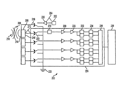
[0043] In Fig. 2 is shown an ultrasonic transducer drive 200 according to a
first
embodiment of the invention. Ultrasonic transducer drive 200 may be used in a
relatively small, inexpensive, and portable ultrasound imaging system 300 such
as
that shown in Fig. 6. Ultrasonic transducer drive 200 may include a signal
generator 202 for producing an outgoing signal 204. In several embodiments,
outgoing signal 204 may be an electrical signal, an electro-magnetic signal,
or an
optical signal.
[0044] If outgoing signal 204 is an optical signal, cross-talk between the
circuits of
' ultrasonic transducer drive 200 may be reduced or eliminated, since optical
signals
do not, in general, interfere with one another. This may allow ultrasonic
transducer
drive 200 to be made smaller than an equivalent electronic device by
increasing the
density of the circuits. In one case, outgoing signal 204 may be processed as
an
optical signal and converted to an electrical signal to drive a transducer. An
integrated circuit comprising ultrasonic transducer drive 200 may be
fabricated out
of gallium-arsenide (GaAs) so that the both the optical circuits and the
electrical
circuits can be fabricated on the same device. In another case, a transducer
utilizing sono-luminescence to convert light directly into sound may be used,
dispensing entirely with any need for an electrical-optical interface.
[0045] In several embodiments, signal generator 202 may be a storage device,
CA 02513447 2005-07-14
WO 2004/064620
PCT/US2004/000888
such as a read-only memory (ROM), an oscillator such as a crystal oscillator,
a
resonant circuit such as a resistor-inductor-capacitor (RLC) or tank circuit,
a
resonant cavity such as a ruby laser or a laser diode or a tapped delay line.
[0046] In the event that signal generator 202 is a storage device, outgoing
signal
204 may have been stored previously, to be read out when needed. In this
embodiment, several versions of outgoing signal 204 may be stored for use with
various objects 242 to be imaged. Ultrasonic transducer drive 200 may thus be
set
to produce a signal appropriate for a particular object 242 to be imaged by
choosing
one of the stored versions of outgoing signal 204.
[0047] In the event that signal generator 202 is an oscillator, outgoing
signal 204
may be a sinusoid of varying frequencies. In this case, outgoing signal 204
may be
generated at an arbitrarily high clock speed and still be forced through
filters of
arbitrarily small bandwidth. This may be advantageous, for example, if a wide
band
signal is inconvenient. A resonant circuit or a resonant cavity may work in a
similar
manner. Furthermore, an oscillator may be used to produce a range of
frequencies, from which a frequency that generates an optimum response may be
selected.
[0048] In the event that signal generator 202 is tapped delay line, outgoing
signal
204 could be generated in a manner similar to a spreading code in a code
division
multiple access (CDMA) format cell phone system. In this case outgoing signal
204
would not need to be a pure sinusoid, but may be a code with a fixed
repetition
length, such as a Walsh or a Gold code. This may, for example, allow an
autocorrelation length of outgoing signal 204 to be adjusted to enhance or
suppress
coded excitation of an incoming signal.
[0049] If signal generator 202 is a tapped delay line it may be followed by an
equalizer to bias or pre-emphasize a range of frequencies in outgoing signal
204.
In one embodiment, the equalizer may be an adaptive equalizer that operates on
an incoming signal analogous to the sound reflected by the imaged object 242.
In
this case, the incoming signal could be measured and the result applied to the
adaptive equalizer to compensate for frequency attenuation of the sound by
amplifying one or more frequencies of the incoming signal or outgoing signal
204 as
necessary. This may be useful if, for example, object 242 attenuates or
absorbs
CA 02513447 2005-07-14
WO 2004/064620
PCT/US2004/000888
sound to the point that no return signal is available for imaging. In one
embodiment, the adaptive equalizer could be placed in parallel with signal
generator 202 and in series with the incoming signal.
[0050] In one embodiment, an equalizer could be placed in series with signal
generator 202. In this case the equalizer could emphasize a particular
frequency or
frequencies in outgoing signal 204. The equalizer may, for example, place a
bias
or pre-emphasis toward lower frequencies on outgoing signal 204. This
embodiment may be appropriate if, for example, object 242 to be imaged is
expected to have features that attenuate lower frequencies significantly more
than
higher frequencies to the extent that imaging may be difficult. The converse
may
be true as well, in that the equalizer may have a bias or pre-emphasis toward
higher frequencies.
[0051] In one embodiment, signal generator 202 may include a generator
amplifier 226 for amplifying outgoing signal 204. Generator amplifier 226 may
pre-
emphasize certain frequencies of outgoing signal 204 to suit the attenuation
characteristics of object 242 to be imaged as well. Signal generator 202 may
also
include an oscillator to produce an appropriate modulation frequency, such as
a
radio frequency (RF) signal, with which to modulate outgoing signal 204.
[0052] Ultrasonic transducer drive 200 may also include a transducer 206 for
converting outgoing signal 204 to outgoing ultrasound 208 at a frequency of
outgoing signal 204. In one embodiment, transducer 206 may have a transmit
side
214 forming an interface with outgoing signal 204. In several embodiments,
transducer 206 may be a piezoelectric element, a voice coil, a crystal
oscillator, a
sono-luminescent transducer, or a Hall effect transducer. In one embodiment,
reversals of outgoing signal 204 produce vibration of .a surface of transducer
206 at
substantially the frequency of outgoing signal 204. In another embodiment,
reversals of outgoing signal 204 produce vibrations of a surface of transducer
206
at frequencies that are significantly higher or lower than the frequency of
outgoing
signal 204, such as harmonics of outgoing signal 204. This vibration may, in
turn,
produce successive compressions and rarefactions of an atmosphere surrounding
the surface of transducer 206, also at substantially the frequency of outgoing
signal
204. If the frequency of outgoing signal 204 is substantially higher than a
frequency
12
CA 02513447 2005-07-14
WO 2004/064620
PCT/US2004/000888
at which sound may be heard, the successive compressions and rarefactions of
the
atmosphere may be termed ultrasound.
[0053] In one embodiment, transmit side 214 may be connected operably to a
transmit switch 218. In several embodiments, transmit switch 218 may be an
electronic switch, an optical switch, a micro-mechanical switch, a transistor,
a field-
effect transistor (FET), a bi-polar transistor, a metal-oxide-semiconductor
(MOS)
transistor, a complementary metal-oxide-semiconductor (CMOS) transistor, a
metal-oxide-semiconductor field-effect transistor (MOSFET), or a clamp diode.
Transmit switch 218 may be connected switchably to signal generator 202 and a
reference potential 220.
[0054] If outgoing ultrasound 208 is reflected by object 242, some of outgoing
ultrasound 208 may return to ultrasound imaging system 300 as reflected
ultrasound 210. In one embodiment, outgoing ultrasound 208 may be delayed or
attenuated partially by object 242. A first portion 248 of outgoing ultrasound
208,
for example, may be reflected immediately upon encountering a nearer surface
244
of object 242 while a second portion 250 of outgoing ultrasound 208 is not
reflected
until it encounters a further surface 246 of object 242. A round trip of
second
portion 250 will thus be longer than a round trip of first portion 248,
resulting in a
delay of second portion 250 relative to first portion 248, as well as delays
of both
first and second portions 248, 250 relative to outgoing ultrasound 208.
Furthermore, second portion 250 may be damped or attenuated by a material of
object 242. The delays may be measured for disparate points of object 242,
,producing an image 276 of object 242.
[0055] In one embodiment, transducer 206 may convert at least a portion of
reflected ultrasound 210 to an incoming signal 212. In several embodiments,
incoming signal 212 may be an electro-magnetic signal, an electrical signal,
or an
optical signal. In one embodiment, transducer 206 may have a receive side 216
forming an interface with incoming signal 212.
[0056] In one embodiment, receive side 216 may be connected operably to a
receive switch 222. In several embodiments, receive switch 222 may be an
electronic switch, an optical switch, a micro-mechanical switch, a transistor,
a field-
effect transistor, a bi-polar transistor, a MOS transistor, a CMOS transistor,
a
13
CA 02513447 2012-10-15
MOSFET, or a clamp diode. Receive switch 222 may be connected switchably to a
signal receiver 224 and reference potential 220.
[0057] In one embodiment, signal receiver 224 may include a receiver amplifier
228 for amplifying incoming signal 212. In one embodiment, signal receiver 224
may further comprise a receiver pre-amplifier 230 for amplifying incoming
signal
212. In one embodiment, signal receiver 224 may include a sample-and-hold 232
for discretizing an amplitude of incoming signal 212. In one embodiment,
signal
receiver 224 may include an analog-to-digital A/D converter 234 for converting
incoming signal 212 to a digital signal.
[0058] In one embodiment, signal receiver 224 may further comprise a filter
270,
such as an analog "brick wall" filter, for filtering out-of-band frequencies
from
incoming signal 212. Filter 270 may be placed ahead of pre-amplifier 230 or
receiver amplifier 228, or both, to protect ND converter 234 from large out-of-
band
dynamics. Filter 270 may be dispensed with if, on the other hand, A/D
converter
234 is fast enough to tolerate large out-of-band frequencies. In this case,
incoming
signal 212 could be converted directly to the digital domain, and the number
of off-
chip components could be reduced.
[0059] In one embodiment, signal receiver 224 may include a register 236 for
storing incoming signal 212. In one embodiment, signal receiver 224 may
include a
digital signal processor 238 for processing incoming signal 212. In one
embodiment, signal receive switch 222 and signal receiver 224 may be
implemented as an integrated circuit. In another embodiment, any or all of the
components of signal receiver 224 beyond A/D converter 234 may be implemented
in software on a microprocessor. Implementation of signal receiver 224 as an
IC or
in software may reduce system size and complexity, and may require only a
single
common connection on transmit side 214 of transducer 206. Thus transmit
complexity may be reduced, but transmit focusin:j may also be rendered
difficult or
impractical. Simulations, however, have shown that reasonable spatial and
contrast resolution may achieved through receive focusing alone while
maintaining
reasonable signal to noise ratios (SNR). One example of such a receive-side
focusing scheme is described in PCT International Application Publication No.
W0US04000887
14
CA 02513447 2005-07-14
WO 2004/064620
PCT/US2004/000888
[0060] In one embodiment, transmit switch 218 may connect transmit side 214 to
signal generator 202 for a first predetermined period of time while signal
generator
202 generates outgoing signal 204. In this embodiment, receive switch 222 may
connect receive side 216 to signal receiver 224 for a second predetermined
period
of time while signal receiver 224 receives incoming signal 212. Transmit
switch
218 may connect transmit side 214 to reference potential 220 during
substantially
second predetermined period of time while signal receiver 224 receives
incoming
signal 212, and receive switch 222 may connect receive side 216 to reference
potential 220 during substantially first predetermined period of time while
signal
generator 202 generates outgoing signal 204.
[0061] In a second embodiment, shown in Fig. 3, signal receiver 224 may
receive
incoming signal 212 while signal generator 202 is generating outgoing signal
204,
in the manner of a full-duplex transceiver. In this embodiment, transmit
switch 218
and receive switch 222 may be dispensed with, and outgoing signal 204 may be
coupled to transmit side 214 while signal receiver 224 is coupled to receive
side
216. In this embodiment, an echo canceller 272 may be inserted between
outgoing
signal 204 and incoming signal 212 to isolate incoming signal 212 from
outgoing
signal 204. Echo canceller 272 may be an equalizer, such as an adaptive
equalizer. A voltage regulator 274, such as a diode running in reverse
breakdown
mode, may also isolate pre-amplifier 230 or receiver amplifier 228 from the
high
voltage levels of outgoing signal 204.
[0062] In a second embodiment, shown in Fig. 3, ultrasonic transducer drive
200
may also include a second transducer 258 having a second transmit side 260 for
converting outgoing signal 204 to a second outgoing ultrasound 262 and a
second
receive side 264 for converting at least a portion of reflected ultrasound 210
and at
least a portion of second reflected ultrasound 242 to a second incoming signal
266.
In this embodiment, second transmit side 260 may be connected operably to
transmit switch 218 so transmit switch 218 can connect second transmit side
260
switchably to signal generator 202 for substantially first predetermined
period of
time and connect second transmit side 260 to reference potential 220 for
substantially second predetermined period of time. In this embodiment, second
receive side 264 may be connected operably to a second receive switch 268 so
CA 02513447 2005-07-14
WO 2004/064620
PCT/US2004/000888
second receive switch 268 can connect second receive side 264 switchably to
signal receiver 224 for substantially second predetermined period of time and
connect second receive side 264 to reference potential 220 for substantially
first
predetermined period of time. Incoming signal 212 and second incoming signal
266 are thus carried over separate channels to signal receiver 224. In one
embodiment, signal receive switch 222, second receive switch 268, and signal
receiver 224 may be implemented as an integrated circuit.
[0063] In a third embodiment, shown in Fig. 4, ultrasonic transducer drive 200
may include an array of transducers 258-1 - 258-n, each having a transmit side
260-1 - 260-n for converting outgoing signal 204 to outgoing ultrasound 208
and a
receive side 264-1 - 264-n for converting at least a portion of reflected
ultrasound
210 to incoming signals 266-1 - 266-n. In this embodiment, each transmit side
260-
1 - 260-n may be connected operably to transmit switch 218 so transmit switch
218
, can connect all of transmit sides 260-1 - 260-n switchably to signal
generator 202
for substantially first predetermined period of time and connect all of
transmit sides
260-1 - 260-n to reference potential 220 for substantially second
predetermined
period of time. In this embodiment, each receive side 264-1 - 264-n may be
connected operably to a separate receive switch 268-1 - 268-n so each receive
switch 268-1 - 268-n can connect each receive side 264-1 - 264-n switchably to
signal receiver 224 for substantially second predetermined period of time and
connect each receive side 264-1 - 264-n to reference potential 220 for
substantially
first predetermined period of time. Receive switches 268-1 - 268-n thus form
an
array, and each incoming signal 266-1 - 266-n may be carried over a separate
channel to signal receiver 224.
[0064] In a fourth embodiment of invention, a method of driving an ultrasonic
transducer 206 may include the steps of generating an outgoing signal 204,
connecting a receive side 216 of transducer 206 to a reference potential 220,
transducing outgoing signal 204 to outgoing ultrasound 208 with transducer
206,
disconnecting receive side 216 of transducer 206 from reference potential 220,
receiving at least a portion of reflected ultrasound 210 at transducer 206,
transducing reflected ultrasound 210 to an incoming signal 212 with transducer
206, and converting incoming signal 212 to an image.
16
CA 02513447 2013-10-24
=
[0065] In a fifth embodiment of invention, the method of driving an
ultrasonic
transducer 206 may further include the steps of switching transmit side 214 of
transducer
206 to receive outgoing signal 204 while outgoing signal 204 is being
generated, switching
transmit side 214 of transducer 206 to reference potential 220 while reflected
ultrasound
210 is being received, or switching receive side 216 of transducer 206 to
signal receiver 224
while reflected ultrasound 210 is being received.
[0066] In a sixth embodiment, shown in Fig. 7, ultrasonic transducer
drive 700 may
include transducer 206 for converting outgoing signal 204 to outgoing
ultrasound 208 and
for converting at least a portion of reflected ultrasound 210 to incoming
signal 212. In one
embodiment, transducer 206 may have transmit side 214 and receive side 216.
[0067] In this embodiment, transmit side 214 may be connected
conductably to
signal generator 202 during at least first predetermined period of time, while
receive side
216 may be connected conductably to signal receiver 224 during at least second
predetermined period of time. In this embodiment, a shunt 290 may be
connectable
between receive side 216 and reference potential 220. In this embodiment,
signal generator
202 may generate outgoing signal 204 during at least substantially first
predetermined
period of time while shunt 290 connects receive side 216 to reference
potential 220. In this
embodiment, signal receiver 224 may receive incoming signal 212 during
substantially
second predetermined period of time while shunt 290 may be substantially open.
When the
RX signal is asserted, the transducer common node is connected to ground and
the receive
signal is developed across the preamplifier input. When the TX signal is
asserted, the off-
chip transmit amplifier drives a large voltage pulse onto the common node of
the array.
During this transmit pulse, all of the transducer current is to be shunted
through the on-chip
switching elements to the off chip voltage source reference potential 220.
[0068] In one embodiment, a second transducer 258 may have second
transmit side
260 for converting outgoing signal 204 to second outgoing ultrasound 262 and
second
receive side 264 for converting at least a portion of reflected ultrasound 210
and at least a
portion of second reflected ultrasound 242 to second incoming signal 266. In
this
embodiment, second transmit side 260 may be connected conductably to signal
generator
202 during at least substantially first predetermined period of time. In this
embodiment,
second receive side 264 may be connected conductably to signal receiver 224
during at
least substantially second predetermined period of time. In this embodiment,
second shunt
290 may be connectable between second receive side 264 and reference potential
220. In
this embodiment, second shunt
17
CA 02513447 2005-07-14
WO 2004/064620
PCT/US2004/000888
298 may connect second receive side 264 to reference potential 220 during at
least
substantially first predetermined period of time while signal generator 202
generates outgoing signal 204. In this embodiment, signal receiver 224 may
receive second incoming signal 266 during substantially second predetermined
period of time while second shunt 298 is substantially open.
[0069] In one embodiment, transmit side 214 may be connected operably to
transmit switch 218, transmit switch 218 may be connectable switchably to
signal
generator 202 and to reference potential 220, and transmit switch 218 may
connect
transmit side 214 to signal generator 202 for substantially first
predetermined
period of time while signal generator 202 generates outgoing signal 204 and
transmit switch 218 connects transmit side 214 to reference potential 220 for
substantially second predetermined period of time.
[0070] In one embodiment, receive side 216 may be connected operably to
receive switch 222, receive switch 222 may be connectable switchably to signal
receiver 224, and receive switch 222 may connect receive side 216 to signal
receiver 224 for substantially second predetermined period of time while
signal
receiver 224 receives incoming signal 212.
[0071] When incoming signal 212 is asserted, a common node of transducer 206
may be connected to reference potential 220 and incoming signal 212 may be
developed across an input of pre-amplifier 230. When outgoing signal 204 is
asserted, on the other hand, generator amplifier 226 may drive a large voltage
pulse onto the common node of transducer 206.
[0072] In one embodiment, substantially all of outgoing signal 204 may be
shunted through the on-chip switching elements to the off chip voltage source
RecBias while outgoing signal 204 is being asserted. For a 100 V outgoing
signal
204 with a 25 ns rise time and a transducer 206 capacitance of 4 pF, a peak
current of 16 mA may have to be absorbed by each receive channel transmit
switch
218. For a single channel this may be straightforward, but for a 1024 channel
chip,
over 16 Amperes of peak current may have to be shunted off chip! (Power
dissipation may not be an issue since the duty cycle may be typically less
than
0.1%.) An equivalent series resistance to RecBias may therefore be less than
0.2 ohms to keep on-chip voltage swings below 3V. The series inductance
further
18
CA 02513447 2012-10-15
exacerbates this problem. In one embodiment, the IC may be a dense ball-grid
array package. In another embodiment, the IC may be a flip-chip solder bump
arrangement. in this embodiment the IC may provide a large number of parallel
shunting paths and minimize series inductance and resistance.
[0073] Simulations have shown that the on-chip switching elements made with
standard CMOS transistors can be made compatible with the required peak
shunting currents. Bipolar transistors are also capable of switching the
required
current levels. Transmit switch 218 and receive switch 222 can be made with
commercially available high-voltage MOS or bipolar transistors.
[0074] It should also be clear that this may be compatible with multiple
transmit
signals. If the transducer fabrication is modified, one might create a
transducer
array with several transmit quadrants. This would allow some level of
rudimentary
transmit focusing while still reducing the number of high-voltage transmit
circuits
and simplify the protection of the receive circuits.
[0075] One skilled in the art would appreciate that a variety of tissue
information
may be obtained through judicious pulse transmission and signal processing of
received echoes with the current invention. Such information could be
displayed in
conjunction with or instead of the aforementioned echo information.
[0076] One such type of information may be referred to as color flow Doppler
as
described in U.S. Patent No. 4,573,477 to Namekawa et al., entitled
"Ultrasonic.
Diagnostic Apparatus," hereby incorporated by reference herein in its
entirety.
Another useful type of information may be harmonic image data as described in
U.S. Patent No. 6,251,074 to Averkiou et al., entitled "Ultrasonic Tissue
Harmonic
Imaging" and U.S. Patent no. 5,632,277 to Chapman et al., entitled "Ultrasound
Imaging System Employing Phase Inversion Subtraction to Enhance the Image,"
both of which are hereby incorporated by reference herein in their entirety.
Yet
another type of information that may be obtained and displayed may be known as
Power Doppler as described in U.S. Patent No. 5,471,990 to Thirsk, entitled
"Ultrasonic Doppler Power Measurement and Display System, ".
[0077] Angular scatter information might also be acquired using a method
described in a co-pending U.S. Patent Application No. 10/030,958, entitled
19
CA 02513447 2012-10-15
"Angular Scatter Imaging System Using Translating Apertures Algorithm and
Method Thereof," filed June 3, 2002,
Speckle may be a common feature of ultrasound images. While it may be
fundamental to the imaging process, many users find its appearance confusing
and
it has been shown to limit target detectability. A variety of so called
compounding
techniques have been described which could be valuable for reducing the
appearance of speckle in ultrasound transducer drive images. These techniques
include spatial compounding and frequency compounding, both of which are well
described in the literature.
[0078] One skilled in the art would appreciate, that the common practice of
frequency compounding could be readily applied to the current invention. By
transmitting a plurality of pulses at different frequencies and forming
separate
detected images using the pulses one may obtain multiple unique speckle
patterns
from the same target. These patterns may then be averaged to reduce the
overall
appearance of speckle.
[0079] The well known techniques of spatial compounding may also be applied to
the current invention. The most conventional form of spatial compounding,
which
we call two-way or transmit-receive spatial compounding, entails the
acquisition of
multiple images with the active transmit and receive apertures shifted
spatially
between image acquisitions. This shifting operation causes the speckle
patterns
obtained to differ from one image to the next, enabling image averaging to
reduce
the speckle pattern.
[0080] In another technique, which we term one-way, or receive-only spatial
compounding, the transmit aperture may be held constant between image
acquisitions while the receive aperture may be shifted between image
acquisitions.
As with two-way spatial compounding, this technique reduces the appearance of
speckle in the final image.
[0081] In many ultrasound applications the received echoes from tissue have
very small amplitude, resulting in an image with poor signal to noise ratio.
This
problem may be addressed through the use of a technique known as coded
excitation. In this method the transmitted pulse is long in time and designed
so that .
CA 02513447 2012-10-15
it has a very short autocorrelation length. In this manner the pulse is
transmitted
and received signals are correlated with the transmitted pulse to yield a
resultant
signal with good signal to noise ratio, but high axial resolution (short
correlation
length). This method could be readily applied in the present invention
ultrasound
transducer drive device and method to improve the effective signal to noise
ratio.
The coded excitation technique is described in U.S. Patent No. 5,014,712 to
O'Donnell, entitled "Coded Excitation for Transmission Dynamic Focusing of
Vibratory Energy Beam.
[0082] An aspect in fabricating a system like the present invention ultrasound
transducer drive is in construction of the transducer array. Both cost and
complexity
could be reduced by incorporating a transducer fabricated using
photolithographic
techniques, i.e. the transducer is formed using micro electro mechanical
systems
(MEMS). One particularly attractive approach has been described in U.S. Patent
No. 6,262,946 to Khuri-Yakub et al., entitled "Capacitive Micromachined
Ultrasonic
Transducer Arrays with Reduced Cross-Coupling ".
[0083] While the present invention may be embodied in many different forms, a
number of illustrative embodiments are described herein with the understanding
that the present disclosure is to be considered as providing examples of the
principles of the invention and such examples are not intended to limit the
invention
to preferred embodiments described herein and/or illustrated herein.
Broad Scope of the Invention:
[0084] While illustrative embodiments of the invention have been described
herein, the present invention is not limited to the various preferred
embodiments
described herein, but includes any and all embodiments having equivalent
elements, modifications, omissions, combinations (e.g., of aspects across
various
embodiments), adaptations and/or alterations as would be appreciated by those
in
the art based on the present disclosure. The limitations in the claims are to
be
interpreted broadly based on the language employed in the claims and not
limited
to examples described in the present specification or during the prosecution
of the
application, which examples are to be construed as non-exclusive. For example,
in
the present disclosure, the term "preferably" is non-exclusive and means
21
CA 02513447 2005-07-14
WO 2004/064620
PCT/US2004/000888
"preferably, but not limited to." In this disclosure and during the
prosecution of this
application, means-plus-function or step-plus-function limitations will only
be
employed where for a specific claim limitation all of the following conditions
are
present in that limitation: a) "means for" or "step for" is expressly recited;
b) a
corresponding function is expressly recited; and c) structure, material or
acts that
support that structure are not recited. In this disclosure and during the
prosecution
of this application, the terminology "present invention" or "invention" may be
used
as a reference to one or more aspect within the present disclosure. The
language
present invention or invention should not be improperly interpreted as an
identification of criticality, should not be improperly interpreted as
applying across
all aspects or embodiments (i.e., it should be understood that the present
invention
has a number of aspects and embodiments), and should not be improperly
interpreted as limiting the scope of the application or claims. In this
disclosure and
during the prosecution of this application, the terminology "embodiment" can
be
used to describe any aspect, feature, process or step, any combination
thereof,
and/or any portion thereof, etc. In some examples, various embodiments may
include overjlapping features. In this disclosure, the following abbreviated
terminology may be employed: "e.g." which means "for example;" and "NB" which
means "note well."
25
22