Note: Descriptions are shown in the official language in which they were submitted.
CA 02513459 2005-07-14
WO 2004/064598 PCT/US2004/001062
ULTRASONIC MONITOR FOR MEASURING
HEART AND PULSE RATES
CROSS-REFERENCES TO RELATED APPLICATIONS
[0001] The instant nonprovisional application is a continuation-in-part of
parent
nonprovisional patent application no. 10/346,296, filed January 15, 2003 and
incorporated by
refereizce herein for all purposes.
BACKGROUND OF THE INVENTION
a) Field of the Invention
[0002] The present invention relates to ultrasonic monitors for measuring
heart and pulse
rates in living subjects. Methods for measuring heart and pulse rates of
living subjects
through ultrasonic means are also encompassed by the instant invention.
b) Description of Related Art
Measuring Heart and Pulse Rates
(0003] Measuring heart and pulse rates in living subjects has been
accomplished by various
means. The pulse rate is commonly measured by lightly touching one's fingers
over an artery
and counting the rate of pulsation. The heart rate is usually measured by a
sensing device
using electrodes that monitor the electrical activity of the heart (e.g.,
contact monitors) based
on electrocardiograms (EKG OR ECG). Measuring rate values is a useful tool in
individualizing and optimizing exercise regimens. Individuals who want to
increase
endurance or performance aim for certain target heart rates to maximize
progression towards
their goals. Conversely, adults with a history of heart disease must avoid
exceeding a certain
heart or pulse rate to reduce unnecessary strain on the heart and resultant
injury.
[0004] The heart rate is the rate of contractions over a given time period,
usually defined in
beats per minute. A pulse can be defined as the rhythmical dilation of a
vessel produced by
the increased volume of blood forced into the vessel by the contraction of the
heart. The
pulse can be felt at many different points on the body, including the wrist
(radial artery) and
neck (carotid artery), which are among the most easily accessible points.
Since a heart
contraction almost always produces a volume of blood that can be measured as a
pulse, the
CA 02513459 2005-07-14
WO 2004/064598 PCT/US2004/001062
heart rate and pulse rate are usually the same. However, there are certain
situations where the
pulse rate may differ from the heart rate. For example, the body may generate
an irregular
heart beat or a premature heart beat. In this scenario, a heart contraction
would not force out
enough blood to be measured as a pulse and the measured pulse rate would be
different from
the heart rate.
[0005] Heart rate monitors that provide continuous heart rate readings rather
than a single
point measurement require wearing a chest strap. There are a few heart rate
monitors that do
not require a chest strap. Most, if not all, of these monitors do not provide
continuous heart
rate readings but measure the wearer's pulse and transmit that pulse upon
request. Most users
would have to stop exercising in order to get this type of measurement, which
is disruptive to
an exercise regimen. In US Patent Nos. 5,738,104 and 5,876,350 and European
Patent No.
086104581, Lo et al disclosed an EKG heart rate monitor that does not require
a chest strap
so that the user does not have to stop exercising to take a heart rate
measurement. All the
sensors and electronics are contained in a wristwatch. The software is
effective in filtering
out muscle motion noise. Therefore the user can walk and jog while taking a
single point
measurement. However, this technology still does not offer continuous
readings. Hence,
most users or heart patients that demand continuous heart rate readings choose
a monitor that
requires a chest strap. Most of the population, including the elderly, would
prefer a monitor
that does not require a chest strap. There are also portable patient monitors
(e.g., vital signs
monitors, fetal monitors) that can perform functions as diverse as arrhythmia
analysis, drug
dose calculation ECG waveforms cascades, and others. However, such monitors
are usually
fairly large (e.g., size of a small TV) and are connected to the patient
through specific wires.
The art has, thus, a need for an improved heart monitoring device,
specifically one that
provides continuous heart rate readings for both healthy and compromised
living subj ects
without the need for chest straps, wirings, or the like.
[0006] Since the advent of the wristwatch, the wrist has offered a convenient,
accessible,
and non-intrusive location for an individual to wear a mechanical device.
Moreover, the
shallow depth of the radial artery in the wrist offers a number of advantages
for allowing the
continuous detection of blood rate pulses. Many different sensor types for
pulse detection in
the wrist have previously been developed.
[0007] Im & Lessard, in "Proceedings of IEEE-EMBC & CMBEC", 2:1033-1034 (1995)
and Tamura et al., in "Proceedings of IEEE-EMBC & CMBEC", 2:1591-1592 (1995)
CA 02513459 2005-07-14
WO 2004/064598 PCT/US2004/001062
describe implementation. Pulse detection in heart rate measurement has been
implemented
by means of piezoelectric sensors where the mechanical stimulus generated by
the pressure
pulse is converted to an electrical signal for further signal processing.
[000] Dupuis & Eugene, in "IEEE Transaction on Instrumentation & Measurement",
49:498-502 (2000) describe use of a strain gauge differential pressure sensor
in a
measurement system, where a low pressure cuff was wrapped around the wrist and
then the
pressure modulation in the cuff caused by the pressure pulse was measured with
strain
gauges.
[0009] Sorvoja H., in her Licentiate Thesis, University of Oulu (1998 - in
Finnish) and
Ruha et al., in Proceedings of Biosignal 1:198-200 (1996) describe utilization
of new
pressure sensitive materials like electromechanical film (EFMi) and
polyvinylidene fluoride
(PVDF) in sensors for pulse detection in the radial artery
[0010] Gagnadre et al., in Electronic Letters, 32:1991-1993 (1998) describes
the use of
fiber optic sensors to detect heart rate. A multimode optical fiber was placed
between two
aluminum plates. The force generated by the pressure pulse caused variation in
the modal
distribution in the fiber and the pulse is detected using a photodetector.
[0011] Infrared optical sensors in cardiovascular pulse detection typically
measure the
optical power variation which is due to absorption or scattering when the
amount of blood in
the measurement volume varies. This kind of measurement, known as photo-
plethysmography (PPG), was first disclosed by Herztman, "Photoelectric
Plethysmography of
the fingers and toes in man", Proceedings of the Society for Experimental
Biology and
Medicine 37:1622-1637 (1937).
[0012] PPG is mainly used for measuring pulsation in a capillary network.
Workers such
as Hast, "Optical heart rate detection structures & methods. Thesis for the
Diploma Engineer
Degree", University of Oulo (Finnish), and Aritomo et al., "A wrist-mounted
activity and
pulse recording system", Proc. of 1st Joint BMES/EMBS Conf. 2:693 (1999), have
applied
PPG to measurements above the radial artery.
[0013] Sensors that monitor pressure pulses in the wrist such as mentioned
above suffer a
common problem. The pressure pulses are generally attenuated by the tissues
between the
artery and the sensor such that much of the high frequency components in the
signal are lost.
When the subject is in motion, muscle movement may create substantial noise at
the pressure
CA 02513459 2005-07-14
WO 2004/064598 PCT/US2004/001062
sensors. These noise signals are low frequency in nature. They will thus make
it very
difficult to identify blood pressure pulses reliably. Photo-plethysmography
(PPG) suffers
similar problem that when the interface between the photo detector and the
wrist is not stable
due to motion, the intensity of the transmitted or reflected light signal may
be significantly
disturbed.
[0014] The ambient lighting condition also plays an important role to the
effectiveness of
PPG technology. The various different technologies using strain gauge,
piezoelectric film
material, infrared optical coupler pair and fiber optic sensor can only
measure heart rate with
reasonable reliability when the subject is still. They are not practical for
sports, fitness and
rehabilitation applications where the subject is moving.
[0015] It is well known in the prior art to employ sonar technology to
identify moving
objects. A piezoelectric crystal may be used both as the power generator and
the signal
detector. In this case, the ultrasonic energy is emitted in a pulsed mode. The
reflected signal
is picked up by the same crystal after the output power source is turned off.
The time
required to receive the reflected signal depends upon the distance between the
source and the
object. The frequency shift, better known as Doppler shift, is dependent upon
the speed of
the moving object. This technique requires only one crystal but the detector
circuit will only
work after the transmitter power is turned off. It is conceivable to use this
method to detect
the motion of a blood vessel wall to extract the pulse rate information.
However, for
superficial blood vessels this technique requires very high speed power
switching due to the
short distance between source and object. In addition, muscle movement will
also generate
reflections that compromise the signal-to-noise-ratio in the system. The
muscle noise signal
in this case is very similar to the signal due to blood vessel wall motion.
Therefore, it is very
difficult to detect heart rate this way when the living subject is in motion.
The advantage of
this approach, however, is low cost and low power consumption. For continuous
mode two
piezoelectric elements may be used. Either may be used as the transmitter and
the other as
receiver or detector at a given time. These two elements can be positioned at
an angle to the
direction of the flow on opposite sides or on the same side of the conduit. If
they are on the
same side, the two crystals can be conveniently packaged into a module. The
flow rate or
flow velocity is proportional to the Doppler shift relative to the operating
frequency. The
main advantage of continuous mode for pulse rate application is that the
Doppler shift due to
blood flow is distinctly different from the shifts due to muscle artifacts or
tissue movement.
The shift due to blood flow is higher in frequency than that due to muscle
motion. Therefore,
CA 02513459 2005-07-14
WO 2004/064598 PCT/US2004/001062
even if the muscle motion induced signals are larger in amplitude, they may
still be filtered
out by a high pass filter in either analog or digital form to retain the blood
flow signals. In
this respect the ultrasound method is superior to infrared, pressure sensing
and even EKG
based technologies.
[0016] One device useful for the measurement of heart and pulse rates is an
electronic unit
worn on the wrist. Several such devices are known in the art. U.S. Patent No.
4,086,916
(Freeman et al.) discloses a cardiac wristwatch monitor having ultrasonic
transducers
mounted in the wrist strap portion. The transducers are encased in an epoxy
and covered
with an insulative coating. U.S. Patent No. 4,163,447 (Orr) discloses a wrist-
mounted
heartbeat rate monitor that relies upon light-emitting diodes. U.S. Patent No.
4,256,117
(Perica et al.) discloses a wrist-mounted combination stopwatch and cardiac
monitor that uses
a pressure transducer to measure pulse rate.
[0017] In Freeman's invention, a wristwatch was intended to offer a continuous
pulse rate
monitor. However, ultrasonic energy is prone to diffraction and attenuation at
the interface of
two media of different densities. Any air gap at the interface or any air
bubbles in the media
will also make ultrasonic energy transfer unreliable. Therefore, it has been a
standard
practice to apply water or an aqueous gel between the transducer module and
the living
subject to eliminate any air gap. Unfortunately water and aqueous gels dry up
quickly in
open air. For continuous rate monitoring, the requirement to apply water or
gel frequently is
not acceptable. In U.S. Patent Nos. 6,371,920 B1 and 6,394,960 B1 attempts
were made to
overcome this problem by using an array of small transducers protruding from
the support
surface to make firm contact with a living subject with no air gap in between.
However, this
increases the complexity and cost of the transducer device and its driving
electronics
significantly. The air gap will not be totally removed, either, due to body
hairs and the
variable condition of skin from person to person. In U.S. patent No. 6,447,456
B 1, two sets
of transducers are used at the radial artery and the ulnar artery. The idea is
to cope with the
compromised signal quality due to motion at the wrist that may create an air
gap from time to
time. With two sets of transducers the hope is that at least one of them will
reliably detect the
Doppler signal to identify the heart beat. The disadvantages of continuous
mode over pulsed
mode are higher cost and more power consumption.
CA 02513459 2005-07-14
WO 2004/064598 PCT/US2004/001062
BRIEF SUMMARY OF THE INVENTION
[0018] The present invention relates to an ultrasonic monitor for measuring
rate values of a
living subject, including heart rate and pulse rate. Due to continued advances
in piezoelectric
material and microelectronic technologies, an ultrasound based pulse rate
monitor system can
be miniaturized to reduce cost and power consumption.
[0019] One aspect of the invention provides an ultrasonic monitor for
measuring pulse rate
values in a living subject, including a module with at least one source of
ultrasonic energy, a
gel pad comprised of a polymer and from about 50 to about 95 % by weight of an
ultrasound
conductive diluent, wherein the gel pad is positioned in direct contact
between the module
and the living subject; an ultrasonic energy detector and associated hardware
and software for
detecting, calculating and displaying a readout of the measured rate values.
The gel pad is
made of a polymer having the following characteristics:
[0020] a) Hardness: Needle Penetration from about 5 to about 300 (1/10 mm)
according
to ASTM D15, preferably from about 25 to about 150, and most preferably from
about 30 to
about 50;
[0021] b) Tensile Stren_ tg-h from about 5 to about S00 psi according to ASTM
D412,
preferably from about 10 to about 300 psi, and most preferably from about 50
to about 200
psi; and
[0022] c) Elongation from about 50% to about 800% according to ASTM D412,
preferably from about 200% to about 700%, and most preferably from about 300%
to about
500%.
[0023] The gels are stable after stress and temperature cycling (with no oil
exuding out).
The display may optionally include electronics and software for analyzing the
rate values
from a living subject. Conversely, the module may include the electronics and
software for
analysis of the rate values.
[0024] Another aspect of the invention provides a method of measuring rate
values of a
living subject. The method includes providing an ultrasonic monitor as
described above and
contacting the monitor with the living subject.
CA 02513459 2005-07-14
WO 2004/064598 PCT/US2004/001062
BRIEF DESCRIPTION OF THE DRAWINGS
[0025] The present invention is best understood when read in conjunction with
the
accompanying figures which serve to illustrate the preferred embodiments. It
is understood,
however, that the invention is not limited to the specific embodiments
disclosed in the
figures.
[0026] Figure lA depicts a front view of an ultrasonic monitor of the instant
invention.
Shown here is a wristwatch with attached wristband (10) having a module (20)
with a gel pad
(30), wherein the gel pad contacts the skin of a living subject. The figure
also depicts the
display unit (40) which provides a readout of measured rate values.
[0027] Figure 1B depicts a front view of an alternative embodiment of an
ultrasonic
monitor in accordance with the present invention.
[0028] Figure 2 depicts a cross sectional view of a transducer module
assembly. The
substrate of the housing (10) may be metal or plastic. The transducers (20)
are molded in
ABS and permanently adhered to the housing. On top of the transducer module
(30), there is
an optional thin adhesive layer (40) which can be a lower oil content gel or
an appropriate
adhesive material. The top structure is the gel pad (50) that is in direct
contact with the living
subj ect.
[0029) Figure 3 depicts a block diagram of a typical ultrasound based heart
rate monitor
system.
[0030] Figure 4 depicts the block diagram of the software of this invention.
The amplified
Doppler signal after anti-aliasing filtering is sampled by an A/D converter in
a
microcontroller. The sampled data is further digitally filtered by a high pass
filter or a
combination of high pass and low pass filters. The output is applied with
either an absolute
value operator or a square operator followed by a stage of low pass filter.
Finally this
digitally processed data is used to determine the pulse rate.
[0031] Figures SA-C depict arrangements of two piezoelectric elements in a
transducer
module.
[0032] Figures 6A-C show depicts a few possible shapes of gel pads designed
for a given
bias angle and a given focal depth.
CA 02513459 2005-07-14
WO 2004/064598 PCT/US2004/001062
DETAILED DESCRIPTION OF THE INVENTION
a) Definitions and General Parameters
[0033] The following definitions are set forth to illustrate and define the
meaning and scope
of the various terms used to describe the invention herein.
[0034] The terms "ultrasonic" and "ultrasound" are used interchangeably herein
and refer to
a sound wave having a frequency between about 30 KHz and about 30 MHz. An
"ultrasonic
transducer" (i.e., a transducing means) is a device used to introduce sonic
energy into a test
object (e.g., living subject) and also to detect reflected energy from the
object as in the instant
invention. Typical of this type of device are piezoelectric crystals which
respond to electric
pulses from an instrument with a mechanical pulse, and to mechanical pulses
(reflected
energy) from the test object with electrical energy detectable by the
instrument. Ultrasound
may also be used as a sound wave imaging technique used to examine a part of
the body
(e.g., breast, abdomen, heart) in order to evaluate a specific tissue or
progression of a
diseased tissue. In addition, ultrasound is used to monitor fetuses and their
growth.
1 S [0035] A "rate value" as used herein, refers to a value that can be
measured. A rate value
of the instant invention includes, but is not limited to, a heart rate, pulse
rate, fetal heart rate,
and fetal pulse rate.
[0036] The term "module with transducing means" refers to the assembly that
contains the
piezoelectric transducer. See, for example, Figure 2. The module may
optionally include
electronics for analysis of the rate values.
[0037] The term "thermoset gel" as used herein refers to a gel that is
generally made of a
chemically bonded three-dimensional elastomeric network which entraps a large
amount of
low volatility liquids or diluents. The elastomeric network is permanent and
cannot be
reversed to a liquid state through heating. A certain amount of diluent is
necessary in order to
ensure good conformability of the gel to the skin and low attenuation for
ultrasound
transmission while still maintaining the load bearing properties. The gel can
be used at a
temperature that ranges from -30°C to +70°C, wherein the gel
maintains its shape and load-
bearing elastic properties. A "silicone gel" or a " polyurethane gel" is an
example of a
thennoset gel. Prior to this invention, thermoset gels have not been used as
ultrasound
transmission media.
CA 02513459 2005-07-14
WO 2004/064598 PCT/US2004/001062
[0038] The term "thermoplastic gel" as used herein refers to a gel that is
generally made of
a thermoplastic elastomer with a large proportion of interdispersed diluent.
Thermoplastic
elastomers include block copolymers such as styrene-butadiene-styrene, styrene-
isoprene-
styrene, styrene/ethylene-co-butylenes/styrene, and styrene/ethylene-co-
propylene/styrene.
The styrene end blocks form glassy domains at room temperature. The glassy
domains act as
physical crosslinks that provide the elastomeric properties of the polymer.
During heating
above the glass transition temperature of styrene, i.e., about 100°C,
the glassy domains melt
and the polymers revert to a liquid state. During cooling, the glassy domains
re-form again.
Hence, the process is reversible. Other block copolymers, such as ethylene-
(ethylene-co-
butylene)-ethylene copolymers which contains crystalline polyethylene end
blocks, can also
be used to prepare thermoplastic gels. Prior to this invention, thermoplastic
gels have not
been used as ultrasound transmission media.
b) The Ultrasonic Monitor
[0039] One aspect of the invention provides an ultrasonic monitor for
measuring pulse rate
values in a living subject, including a module with at least one source of
ultrasonic energy
(transducer), a gel pad comprised of a polymer and a mineral oil, wherein the
gel pad is
positioned in direct contact between the module and the living subject; an
ultrasonic energy
detector and associated hardware and software for detecting, calculating and
displaying a
readout of the measured rate values. The gel pad is made of a polymer having
the following
characteristics:
[0040] a) Hardness: Needle Penetration from about 5 to about 300 (1/10 mm)
according
to ASTM D15, preferably from about 25 to about 150, and most preferably from
about 30 to
about 50;
[0041] b) Tensile Strength from about 5 to about 500 psi according to ASTM
D412,
preferably from about 10 to about 300 psi, and most preferably from about 50
to about 200
psi; and
[0042] c) Elon_ation from about 50% to about 800% according to ASTM D412,
preferably from about 200% to about 700%, and most preferably from about 300%
to about
500%.
[0043] In a preferred embodiment of the invention, the monitor is a wristwatch
with
attached wristband, wherein the module is attached to the wristband. In
another preferred
CA 02513459 2005-07-14
WO 2004/064598 PCT/US2004/001062
embodiment the transducer includes a first and a second piezoelectric crystal,
wherein the
crystals are positioned at an angle to each other, and wherein the angle is
determined based
on the distance of the transducer to the living subject. The first
piezoelectric crystal is
energized by an original ultrasonic frequency signal, wherein the original
ultrasonic
frequency signal is reflected off the living subject and received by the
second piezoelectric
crystal. More specifically, the module includes a pair of piezoelectric
crystals at an angle to
each other, wherein the angle is determined by the depth of the object being
monitored. If the
object is a fetus deep inside a womb, the two crystals are placed parallel to
each other. If the
object is the radial artery of a human subject (e.g., adult, infant), the
angle of the two crystals
with respect to the direction of the blood flow would be about 0 to about
60°. One of the
crystals is energized at an ultrasonic frequency. The signal is then reflected
back by the
living subject and picked up by the second crystal. The frequency received is
either higher or
lower than the original frequency depending upon the direction and the speed
of the fluidic
mass flow. For example, when blood flow is monitored, the direction of flow is
fixed. Thus,
the Doppler frequency which is the difference between the original and the
reflected
frequency depends only upon the speed of the blood flow.
(0044] The ultrasonic monitor includes an ultrasonic frequency driver, an AM
or FM
detector, an amplifier, filter circuits and a microcontroller. The driver
circuit is composed of
an oscillator running at a frequency between about 30 KHz to about 30 MHz, an
impedance
matching network and a Class C power amplifier. Ultrasonic energy is delivered
to one of
the two piezoelectric elements in the module by the power amplifier. The other
element
picks up the reflected ultrasonic signal. This signal is amplified and then
amplitude
demodulated (AM) or frequency demodulated (FM) to yield the Doppler
frequencies. The
Doppler frequencies in audio range are further amplified and filtered to avoid
aliasing before
they are digitally sampled and processed by a microcontroller with built-in
analog-to-digital
converter and software. The software digitally filters out the noise signals
due to muscle
artifacts by a high pass filter with a 3-db corner frequency at about 10 to
about 1500 Hz
depending on the original ultrasound operating frequency. Following that, a
square operation
and a low pass filter will further condition the signal appropriately for
heart rate arbitration.
The 3-db corner frequency of the low pass filter is about 500 to about 5000 Hz
depending
upon the original ultrasound operating frequency. The heart rate arbitration
logic in the prior
art of Lo et al. may be applied to this invention with minor modifications.
to
CA 02513459 2005-07-14
WO 2004/064598 PCT/US2004/001062
[0045] The module may optionally include electronics and software for
analyzing the rate
values of the living subject, such as heart rate or pulse rate. Alternatively,
the display unit
may include the electronics and software for analyzing the rate values. As
such, there are at
least two alternative embodiments with respect to the wrist watch ultrasonic
monitor.
[0046] In one embodiment of the invention, the transducers, the electronics
and the
software are all housed in the same module. The module is mechanically
attached to the
wrist band and it may be positioned at the radial artery of a living subject.
The gel pad faces
the wrist of the living subject and is held in place by the wrist band. The
two crystals (supf~a)
are located in the interior of the module right behind the gel pad. The
measured blood flow
and/or heart rate values can be sent to the watch display unit via wireless
means. In this case,
the module has a transmitter circuit and the display unit has a receiver
circuit. The carrier
frequency may be chosen based upon conventionally used frequencies, e.g. SKHz,
120I~Hz,
455KHz, 433MHz, 900 MHz, etc. These frequencies are used in various chest
strap heart
rate monitors. Currently, the most popular frequency used is 5 KHz. Therefore,
the module
with all the electronics and software included may be offered as a direct
replacement to the
existing chest strap products in the market. The display unit in this case is
the wristwatch
with wireless receiver circuit built-in. Optionally, the module can be
fastened separately on
its own strap adapted to fit another part of the living subject where blood
flow can be
conveniently monitored. This is the preferred approach since the battery
compartment in the
module may be designed to allow users to replace the battery with ease. The
frequency of
use and the length of time per use determine how frequently the battery needs
to be replaced
for a given type of battery.
[0047] In another embodiment of the invention (shown in Figure lA), the same
electronics
and software are placed within the watch display unit while the transducers
and gel pad are
housed within the module. Cormecting wires are molded into the wrist band to
connect to the
ultrasound driving circuit. In this case, a high energy density battery is
required to reduce the
frequency of battery change. Alternatively, a rechargeable battery may be
employed. The
battery will be charged wirelessly so that the watch unit is waterproof for
swimmers and
divers. As battery technology continues to improve in energy density and
lifetime, this
integrated approach may eventually be preferred. In another embodiment, the
monitor may
be held in place by or integrated into a head band for monitoring temporo
pulses.
11
CA 02513459 2005-07-14
WO 2004/064598 PCT/US2004/001062
[004] In still other embodiments in accordance with the present invention, for
example
embodiment 100 of Figure 1B, the transducers and gel pad are housed within a
first module
130 proximate to a first portion of the subject (i.e. the wrist of one hand),
while the
electronics and software and watch display unit are present within a second,
separate module
140 secured to another part of the subject (i.e. the wrist of the other hand).
The first (sensing)
module may send sensed information to the second (processing/display) module
through a
wireless (preferred) or wired communication medium. In accordance with still
other
embodiments of the present invention, the position of the various processing
functions may
be allocated in any manner between sensing and display modules in different
locations, for
example on different wrists as shown in the specific embodiment of Figure 1B.
[0049] Examples of rate values that can be measured with the ultrasonic
monitor include,
but are not limited to, heart rate values and blood pulse rate values. Such
rate values can be
obtained from human adults, infants, and fetuses or from other animals.
c) Polymers and Gels
[0050] The ultrasonic monitor includes a gel pad which is positioned in direct
contact with
the module and the living subject. Ultrasound energy does not propagate
efficiently through
air, thus a couplant (gel pad) is needed for efficient transmission between
the transducer and
the living subject. Gels in fluidic state may be used as couplants, however,
such fluidic gels
are likely t~ dry up quickly due to being water based. Hence, the instant
invention preferably
employs oil based gels in solid form to achieve efficient transmission between
the transducer
and the object. As such, the gel pad is made of a specific polymer which is
used to conduct
ultrasound waves such that the waves can be converted to measurable rate
values. In a
preferred embodiment, the polymer is a thermoset or thermoplastic gel. The gel
of the
present invention may include any elastomer type, elastomer molecular weight,
crosslinking
density, percentage of diluents, and the like. The gel pad may be about one
square centimeter
in size and its shape may be square, rectangular or round. Examples of
thermoset gels
include, but are not limited to, silicone or polyurethane gels. Silicone gels
can be based on
the reaction between a vinyl terminated polydimethylsiloxane,
polymethylphenylsiloxane, or
polydiphenylsilocaxane, and a hydride terminated polydimethylsiloxane,
polymethylphenylsiloxane, or polydiphenylsiloxane. Polyurethane gels can be
based upon the
reaction of polybutadienediol, polybutadienetriol, poly(ethylene-co-
propylene)diol,
poly(tetraethylene oxide)diol, polyethylene oxide)diol, or castor oil with
polyisocyanates
12
CA 02513459 2005-07-14
WO 2004/064598 PCT/US2004/001062
such as toluene diisocyanate, or methylene diisocyanates. Examples of
thermoplastic gels
include, but are not limited to, styrene-(ethylene-co-butylene)-styrene,
styrene-(ethylene-co-
propylene)-styrene, styrene-butadiene-styrene, styrene-isoprene-styrene
ethylene-(ethylene-
co-butylene)-ethylene and other elastomeric block copolymers.
[0051] The term "gel" is often used to describe a wide variety of materials
which may have
different properties. The art generally distinguishes three types of gels:
thickened fluids,
hydrogels, and stable soft elastomeric gels. Examples of thickened fluids are
toothpastes,
dishwasher detergents, and the like. These fluids are typically thickened by
fumed silica,
bentonite clay, or other inorganic thickening agents. Upon gentle shaking or
squeezing, this
type of gel flows readily in a liquid-like fashion. However, this gel cannot
recover its
original thickened shape. Such gels are, thus, not suitable for applications
where the gel
needs to take on a specific shape or form.
(0052] Hydrogels typically include water soluble, high molecular weight
polymers such as
polyvinyl alcohol), polyacrylamide, poly(acrylic acid), and the like.
Hydrogels also contain
a high percentage of water or water compatible fluids such as glycol. Hence,
hydrogels can
be characterized as water-like fluids or water compatible fluids, thickened by
a high
molecular weight organic polymer. Furthermore, this type of gel, depending on
the
composition, can be a fluid or elastic solid. If a lower molecular weight
water soluble
polymer and/or a high percentage of water is used, a fluid-like hydrogel is
formed. A fluid-
like hydrogel such as AQUASONICTM hydrogel is widely used as a medium for
ultrasonic
transmission. In fact, there are several commercial gel products used for
ultrasonic
transmission, often simply referred to as ultrasound gel or ultrasound
transmission gel. U.S.
Patent Nos. 6,328,695; 6,251,076; and 6,159,149 refer to the use of a gel as
transmission
medium with respect to their patented ultrasonic devices. If a high molecular
weight water
soluble polymer and/or a low percentage of water is used, the gel can form a
soft elastic solid
which is capable of carrying a moderate level of mechanical stress. The
elasticity is derived
from the temporary network formed by hydrogen bonding of water molecules to
the polar
groups of the polymers. U.S. Patent Nos. 5,265,614 and 5,078,149 as well as JP
Patent Nos.
59-49750 and 59-82838 describe the use of such gels based on polyvinyl
alcohol).
However, since all these fluids and gels are volatile, they tend to evaporate
even at room
temperature and need to be kept in a closed environment (e.g., container,
vacuum). Although
these fluids and gels may possess load-bearing elastic properties for a short
period of time,
they are not stable upon long term exposure to the environment. At elevated
temperature
13
CA 02513459 2005-07-14
WO 2004/064598 PCT/US2004/001062
such as 40°C and higher, the evaporation rate consistently increases,
thereby further
shortening the usefulness of the product. Furthermore, water freezes at
0°C, making this type
of gel or fluid unsuitable for subzero temperatures. Consequently, hydrogels
are only useful
as ultrasound transmission media for a limited application, i.e., where the
application does
not require the gel to last beyond a short period of time.
[0053] When the application requires a gel that can be used for days or
longer, stable soft
elastomeric gel types are required. The elastomeric gels contain an
elastomeric network with
a high percentage of diluents which are generally nonvolatile at ambient
temperatures. They
possess elastic and load bearing properties at ambient conditions for a
prolonged period of
exposure (e.g., several month to a few years). They are stable and maintain
elastic properties
over a wide temperature range, i.e., from subzero temperatures to 70°C.
The art distinguishes
two categories of stable soft elastomeric gels: thermoset gels and
thermoplastic gels.
Thermoset gels are made of a chemically bonded three-dimensional elastomeric
network
which entraps a large amount of low volatility liquids or diluents. The
elastomeric network is
permanent and cannot be reversed to a liquid state through heating. A certain
amount of
diluent is necessary in order to ensure good conformability of the gel to the
skin and low
attenuation for ultrasound transmission while still maintaining the load
bearing properties. In
the absence of the required amount of diluent, the gel would resemble common
rubber or
elastomer which generally have a hardness of greater than 15 Shore A (ASTM
D2240). For
example, U.S. Patent No. 4,901,729 describes the use of peroxide crosslinked
polybutadiene,
sulfur crosslinked polybutadiene, and silicone rubber as ultrasound
propagation media.
Examples of thermoset gels are silicone gels and polyurethane gels.
[0054] The elastomeric network of a silicone gel is formed by silicone rubber
which is
typically cured by reacting a hydride silicone rubber with a vinyl silicone
rubber in the
presence of a platinum catalyst. Both silicone rubbers are highly diluted with
a non-reactive,
low volatility silicone fluid prior to the reaction. The reaction can be
carned out at 110°C -
120°C for 30 minutes, or at room temperature for 4~ hours. The silicone
gels can also be
made by using a silane terminated silicone elastomer which can be cured by
exposure to
ambient moisture. At the end of the reaction, the final composition contains
about 5-45%
silicone rubbers and 95-SS% silicone fluid. A typical silicone gel composition
is exemplifed
in U.S. Patent No. 3,020,260, which is incorporated by reference herein. Some
commercially
available silicone gels include Dow Corning DC 3-4150, DC 3-4154, and Q3-6575;
Sylgard
14
CA 02513459 2005-07-14
WO 2004/064598 PCT/US2004/001062
527; Gelest Gel D200 and D300; and P065 2-part and F065 one-part. Other
silicone gel
suppliers include General Electric Silicones of USA, Wacker Chemie of Germany,
Shin-Etsu
of Japan, and others. Silicone gels have been used for filled prosthesis
devices as described
in U.S. Patent No. 4,455,691 and as sealants as described in U.S. Patent Nos.
5,290,826 and
5,245,980. U.S. Patent Nos. 5,747,694 and 5,900,554 and their foreign
equivalent, JP Patent
No. 9043076, describe the use of a silicone gel in sealing a pressure sensor.
U.S. Patent No.
5,457,352 describes the use of a silicone elastomer applied during the gel
phase of the
adaptation layer in an ultrasonic converter, wherein the composition contains
a large
proportion of high density metal oxide for damping or blocking the ultrasonic
wave.
[0055] The elastomeric network of a polyurethane gel is formed by reacting an
isocyanate
terminated rubber or oligomers (e.g., polybutadiene, polyisoprene,
polytetrahydrofuran, or
dimmer acid) with a hydroxyl terminated rubber or oligomers (e.g.,
polybutadiene,
polyisoprenee, ethylene-butylene rubber, ethylene-propylene rubber, castor
oil, or the like).
Each rubber or oligomer is highly diluted with a nonvolatile and compatible
diluent prior to
1 S the reaction. The diluents include mineral oils, vegetable oils, dibutyl
phthalate, dioctyl
phthalate, polybutenes, paraffmic oils, naphthenic oils, and the like. The
final composition
contains about 5-45% reactive rubbers and 95-55% total diluents. A typical
polyurethane gel
is described in U.S. Patent Nos. 5,083,940; 4,982,054 and 4,962,286, which
disclose the use
of polyurethane gels as sealant in electrical or telecommunication junction
boxes. GB Patent
No. 2,036,504 teaches the use of polyurethane rubber with International Rubber
Hardness
Degree (IRHD) of 15-50.
[0056] A thermoplastic gel is generally made of a thermoplastic elastomer with
a large
proportion of interdispersed diluent. Thermoplastic elastomers include block
copolymers
such as styrene-butadiene-styrene, styrene-isoprene-styrene, styrene/ethylene-
co-
butylenes/styrene (e.g., Kraton polymers by Kraton Inc). Other commercially
available block
copolymers include Septon polymers, which are styrene/ethylene-co-
propylene/styrene (e.g.,
by Kuraray of Japan). In both, Kraton and Septon polymers, the styrene end
blocks form
glassy domains at room temperature. The glassy domains act as physical
crosslinks that
provide the elastomeric properties of the polymer. During heating above the
glassy transition
temperature of styrene, i.e., about 100°C, the glassy domains melt and
the polymers reverse
to a liquid state. During cooling, the glassy domains re-form again. Hence,
the process is
reversible, unlike that in the thermoset gels. Other block copolymers, such as
ethylene-
(ethylene-co-butylene)-ethylene copolymers which contains crystalline
polyethylene end
CA 02513459 2005-07-14
WO 2004/064598 PCT/US2004/001062
blocks, can also be used to prepare thermoplastic gels. The crystalline end
blocks form
crystallites which act as physical crosslinks to give elastomeric properties,
rather than glassy
domains as in the styrene based block copolymers. During heating, the
crystallites melt and
revert to the liquid state. During cooling, the crystallites re-form again.
Similarly, the
process is reversible.
[0057] In order to form a gel with thermoplastic elastomers, a large amount of
low
volatility diluent (e.g., typically 65-95% diluent) is used together with 5-
35% block
copolymers. The block copolymer may be a styrene/ethylene-co-butylene/styrene
block
copolymer with a total molecular weight of 30,000 to 300,000. The molecular
weight of each
styrene block may range from 4,000 to 35,000, and the molecular weight of the
ethylene-co-
butylene may range from 22,000 to 230,000. The weight percentage of the glassy
polystyrene blocks is typically 20-40%, wherein the remaining 60-80% includes
the center
ethylene-co-butylene elastomer block. The suitable diluents include mineral
oil, paraffinic
oil, naphthenic oil, polybutenes, and the like, so long as they are compatible
with the rubbery
center portion of the block copolymers. Examples of gel composition based on
block
copolymers are described in U.S. Patent Nos. 4,369,284 and 4,618,213,
incorporated by
reference herein. U.S. Patent No. 4,618,213 describes the use of gels as toys
or as acoustic
isolators for noise reduction. U.S. Patent Nos. 5,994,446; 5,925,707; and
5,710,206 describe
thermoplastic gels for sealing applications. U.S. Patent Nos. 6,406,499;
5,985,383;
5,925,707; 5,830,237; and 5,766,704, describe the use of thermoplastic gels
for cushioning or
shoe sole applications. U.S. Patent Nos. 6,066,329 and 5,879,694 teach the use
of
thermoplastic gels for making transparent candles. U.S. Patent No. 5,830,136
teaches the use
of thermoplastic elastomer gel in optical sensors. All patents and
publications are
incorporated by reference herein.
[0058] Both thermoplastic and thermoset gels may be used in the instant
invention. The
gels used herein are generally defined by the following properties:
(i) Hardness: 5 < Needle Penetration < 300 (1/10 mm) according to ASTM D15,
preferably 25 < Needle Penetration < 1 S0, and most preferably 30 < Needle
Penetration < 50.
(ii) Stren th: 5 < Tensile Strength < 500 psi (pounds per square inch)
according to
ASTM D412, preferably from 10 to 300 psi, and most preferably from 50 to 200
psi.
(iii) Elon ag t~: 50% < Elongation < 800% according to ASTM D412, preferably
from 200% to 700%, and most preferably from 300% to 500%.
16
CA 02513459 2005-07-14
WO 2004/064598 PCT/US2004/001062
(iv) Stability: The gels are stable after a stress and temperature cycling
(with no oil
exuding out).
[0059] The gels have good adhesion to the plastic housing of the ultrasonic
transducer. The
plastic housing may include acrylonitrile-butadiene-styrene (ABS),
polycarbonate, nylon, and
the like. Preferably, the gels are bonded to the plastic housing to form an
integral unit.
However, the instant invention also encompasses alternative ways to attach
gels to the
ultrasonic transducer.
[0060] In a preferred embodiment of the invention, a thermoplastic gel is over-
molded, i.e.,
directly molded onto the plastic housing of a transducer (including a
piezoelectric acoustic
actuator and sensor), wherein specific molding techniques are employed. Such
techniques
are well known in the plastic industry. For example, the plastic encased
ultrasonic transducer
may be inserted into a mold, wherein a thermoplastic gel is heated to the
molten state and
injected into the mold by using an injection molding machine. The injection
time and
temperature of the gel are monitored to prevent damage to the transducer
itself. In its molten
state, the gel readily flows and eventually adheres to the plastic housing of
the ultrasonic
transducer (i.e., without using an additional adhesive at the interface
between the plastic and
the gel). However, in order to ensure a durable bond, it is preferable to
apply a thin layer of
primer or adhesive onto the surface of the plastic housing before the gel is
molded onto it.
One such suitable adhesive is a thermoplastic gel which has a lower oil
content than the gel to
be molded via injection. Several such lower oil containing thermoplastic gels
are
commercially available, such as Versaflex OM 6000 supplied by GLS Corporation
and
Monprene supplied by Teknor Apex Corporation. The extra layer of primer or
adhesive
functions as a tie-layer between the plastic housing of the transducer and the
acoustic
transmission gel. The plastic housing can be ABS, polycarbonate or nylon. The
surface of
the plastic housing is usually cleaned prior to applying the thin layer of
primer or adhesive
(e.g., with a solvent to remove mold release agents, greases, oils, and dirt).
Having a lower
oil content, the tie-layer has a higher concentration of polymer on the
surface, thus, it can
form a strong bond with the plastic surface. Since the tie-layer also contains
similar chemical
constituents as the acoustic transmission gel, it has good compatibility with
the gel at the
interface. Optionally, the tie-layer may contain additional ingredients that
further improve
adhesion to the plastic housing, such as adhesion promoters, compatibilizers,
coupling agents,
and the like.
17
CA 02513459 2005-07-14
WO 2004/064598 PCT/US2004/001062
[0061] In another preferred embodiment of the invention, the tie-layer is over-
molded by
injection molding. A two-stage insert molding process is preferred, wherein
the tie-layer is
molded first and the acoustic transmission gel is molded second. This process
is particularly
preferred for large scale manufacturing, wherein high quantities of product
are processed. In
an alternative embodiment, the adhesive is pre-dissolved in a suitable solvent
to reduce its
viscosity so it can be applied as a primer onto the plastic housing. In this
technique, the
solvent is allowed to evaporate before the over-molding with the acoustic
thermoplastic
transmission gel takes place. This is particularly useful if the production
volume is lower. In
yet another alternative embodiment, it is possible to cast the thermoplastic
gel onto the tie-
layer coated plastic housing of the transducer surface, instead of injection
molding. In this
technique, the thermoplastic gel is heated to above 150°C, preferably
above 160°C, and most
preferably above 170°C, and then poured onto the plastic housing of the
transducer (which
was inserted into a mold). At those temperatures the thermoplastic gel is
fluid and can be
poured with relative ease. The heating temperature is usually kept below
180°C to prevent
excessive fuming. The flash point of the mineral oil which is used as the
diluent in the
thermoplastic gel is about 220°C.
[0062] Commercially available adhesives may also be used in the instant
invention (e.g.,
adhesives such as EC6000 manufactured by ECLECTIC PRODUCTS, INC., Carson,
California 90745). Commercially available adhesives can be employed to bond
the acoustic
transmission gel onto the plastic housing (e.g., EC6000 adhesive can be
brushed onto the
surface of plastic housing as thin layer prior to the over-molding of the
acoustic transmission
thermoplastic gel).
[0063] In another embodiment of the instant invention, a thermoplastic gel is
directly
molded onto the transducer, i.e., the piezoelectric acoustic actuator and
sensor rather than
onto a plastic housing which contains the transducer. The injection or casting
temperature of
the thermoplastic gel is carefully monitored to prevent damage to the
piezoelectric actuator
and sensor by the high temperature. If an adhesive or primer is used, it is
applied directly
onto the surface of the piezoelectric units prior to overmolding.
(0064] In another preferred embodiment of the invention, a thermoset gel, such
as silicone
or polyurethane, is cast onto the ultrasonic transducer. The gel may be cast
directly onto the
transducer device itself or onto the plastic housing. Thermoset gels are also
available through
commercial suppliers and are generally provided in a two-part liquid form
(i.e., the gel is then
18
CA 02513459 2005-07-14
WO 2004/064598 PCT/US2004/001062
mixed in a preset ratio according to the manufacturer's instructions). The
thermoset gel
mixture is cast around the transducer which is previously put inside a mold
prior to casting.
The casting is left in the mold and heated to a desired temperature to
complete curing of the
gel. Silicone gels can be cured at an ambient temperature of about 23 C for 48
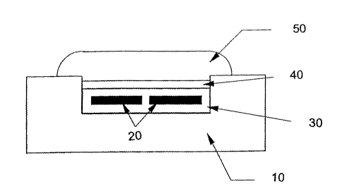
hours, or at
S 120°C for 1 hour. For polyurethane gels, the initial curing
temperature is 1 hour at ambient
temperature of about 23 C, followed by post curing at 100°C for 16
hours. When using
thermoset gels in the instant invention, it is also possible to use an
adhesive or a primer to
ensure good bonding at the interface. For silicone gels, a RTV silicone
adhesive or primer
can be employed. For polyurethane gels, a polyurethane based adhesive is
preferred. In an
alternative embodiment, thermoset gels are applied to the transducer by liquid
injection
molding. The two gel parts are stored in separate tanks, after which they are
pumped into an
inline static mixer according to the desired preset ratio. The mixture is then
injected into the
mold to encapsulate the transducer.
d) Low Frequency Operation
[0065] The application of principles of sonar technology to monitor blood flow
in
accordance with embodiments of the present invention offers the advantage of
retaining the
full frequency content of the signal received. This is achieved by converting
signal received
from the moving target (such as flowing blood), into a Doppler shift in
frequency.
[0066] Specifically, a first piezoelectric device generates an operating
(carrier) ultrasound
signal at a given frequency. The velocity of the moving material within a
subject modulates
this carrier frequency, in a manner analogous to conventional frequency
modulation
technology utilized in an FM radio broadcast. The frequency of the Doppler
shift is linearly
proportional to the velocity of the moving material within a subject.
[0067] A second piezoelectric device picks up the frequency-modulated signal.
The
Doppler shift frequencies are then converted back to the original signal.
[0068] The Doppler effect is employed as a vehicle to transform non-invasively
and
truthfully, the signal of interest (e.g. blood flow pulses) into a voltage
signal. The specific
Doppler frequencies received have no bearing on the specific frequency content
of the
received signal of interest. The Doppler frequencies serve merely as the media
for translation
of the motion of the blood to an electrical signal, from which heart rate and
other vital
information can be computed.
19
CA 02513459 2005-07-14
WO 2004/064598 PCT/US2004/001062
[0069] In theory, independence of blood flow signal from Doppler frequency and
from the
operating/carrier frequency should render all operating frequencies suitable
for use in
accordance with embodiments of the present invention. However, in practice a
number of
important factors must be considered in selecting an operating/carrier
frequency.
[0070] Certain factors favor using a high operating/carner frequency. For
example, the
wrist offers an relatively accessible and convenient location for positioning
the monitoring
device. The relatively shallow focal depth of the radial artery in the wrist
suggests using
ultrasound energy of high frequency suitable for interrogating such shallow
focal depths.
[0071] The size and weight of the device also favors use of a high
operating/carrier
frequency. In general, the smaller an electromechanical resonator, the higher
its emitted
frequency. For a device intended to be worn on the wrist during active
physical exercise, the
size of the transducer and hence its possible range of output frequency, is
limited.
[0072] Still other factors favor the use of a low operating/carner frequency.
[0073] For example, electromechanical transducers operating at a high
frequency tend to
vibrate more rapidly and consume more power than transducers operating at
lower
frequencies. For a blood flow monitor intended to be worn on the wrist, the
available power
supplied by a small battery is limited, and transducer actuation at lower
frequencies is
indicated. The AM or FM amplifier and demodulation circuits in the system will
also
consume less power at lower operating frequency. In principle, the power
consumption is
linearly proportional to the operating frequency.
[0074] Given at least the above consideration of power consumption, and
despite the
disadvantages of blood pulse sensing utilizing low carrier/operating
frequencies described
above, in accordance with certain embodiments of the present invention, it may
be valuable
to detect blood flow utilizing ultrasound energy having a frequency of 2 MHz
or less.
[0075] A number of design factors facilitating heart rate monitoring of the
radial artery
utilizing applied operating/carner frequencies of 2 MHz or less, have been
discovered. These
design factors are shown and described below in connection with Figures 5A-C.
[0076] Figure 5A shows a simplified schematic view of one embodiment of a
device for
heart rate monitoring in accordance with the present invention. Piezoelectric
transducers
520a and 520b are positioned within transducer module 530, separated by a
distance d.
Piezoelectric transducer 520a emits ultrasound signal 550 at the
operating/carner frequency,
CA 02513459 2005-07-14
WO 2004/064598 PCT/US2004/001062
to focal point F of vessel 552 having blood flowing therethrough in the
directions indicated.
Blood vessel 552 is positioned at a focal depth D from transducers 520a-b.
[0077] As blood flows through vessel 552 in the directions indicated, movement
in the wall
of a blood vessel, and in the moving mass of the flowing blood itself, create
shifts in the
Doppler frequency.
[0078] The direction of motion of the blood vessel wall is transverse to the
direction of
blood flow. The amount of transverse motion of the vessel wall is restricted
by its stiffness.
Moreover, the resulting acoustic signal is also dampened by surrounding
tissues, such that the
amplitude and high frequency content of this form of acoustic signal are
compromised.
[0079] By contrast, the mass of the blood driven through the vessel by blood
pressure
pulses, moves relatively freely. When the blood cells are free to move through
the vessel
under this applied pressure, some will travel faster than the others. These
faster-moving cells
will yield higher Doppler frequencies.
[0080] These higher Doppler frequencies can in turn be demodulated into higher
voltage
signals. Therefore, the demodulated signal has larger amplitude. Since the
faster blood cells
have high mobility, the demodulated voltage signals presenting them, will also
be of high
frequency. Since these high frequency signals have higher amplitudes, they
have a much
better chance at being retained after filtering out of the low frequency noise
signals.
[0081] Because of this high frequency component of the mass of blood moving
through the
vessel, even large amplitude, low frequency (< 10 Hz) signals induced by
muscle motion can
be filtered out by a single-stage or a multiple-stage high pass filters in
either analog and/or
digital form. Heart rate information can thus be effectively obtained from the
remaining
high frequency content of the blood flow signal.
[0082] In order to emphasize the high frequency Doppler shift containing
important blood
flow information, Figure SA shows transducers 520a and 520b oriented at an
angle relative to
the direction of flow of the blood. Specifically, emitted ultrasound energy
signal 550 is
incident to vessel 552 at an angle 01, and Doppler-shifted ultrasound energy
signal 554 is
reflected from vessel 552 at an angle 02. This angular orientation of the
transducers relative
to the direction of movement of blood within the vessel can be expressed as
the bias angle:
(1) bias angle = %a(92+01)
21
CA 02513459 2005-07-14
WO 2004/064598 PCT/US2004/001062
[0083] Positioning the two piezoelectric elements of Figures SB-C at a bias
angle of less
than 90° relative to the direction of blood flow, enhances the Doppler
shift in the received
signal according to the following equation:
(2) Fd = 2FdV*cos0/C, where:
Fd = Doppler frequency;
V = flow velocity;
0 = angle of incidence and reflection (82=01) of energy relative to flow
direction; and
C = speed of sound in tissue.
[0084] Per Equation (2), exploitation of the bias angle factor enhances the
Doppler shift of
the received ultrasound signal, according to the component of incident
ultrasound energy
lying in the same direction as the movement (represented by the cosine). This
enhanced
Doppler shift increases the signal-to-noise-ratio at the output of the FM
detector (or the
frequency-to-voltage converter).
[0085] Another design factor which can be exploited to optimize sonar
detection of blood
flow is the orientation of the transducers relative to one another in the
module. Figures SA-C
also shows transducers 520a and 520b inclined relative to each other by a roof
angle:
(3) roof angle = ~2(e2-01)
[0086] The roof angle and distance (d) between the transducers, determines
focal depth
(D). The larger the roof angle, the shallower the focal depth.
[0087] As described above, the bias angle design factor may be exploited to
enhance the
strength of the signal at the output of the demodulator. By contrast, the roof
angle design
factor may be exploited to better focus applied ultrasound energy on the
shallow radial artery,
especially ultrasound energy applied at low operating frequencies.
[0088] Figure SB shows a simplified schematic view of another embodiment of
the present
invention, wherein transducer 560a emitting ultrasound energy 562 to vessel
564 positioned
at much deeper focal depth D', is inclined at a much smaller roof angle and at
a distance (d')
relative to second transducer 560b also present within transducer module 568.
[0089] Utilizing a large roof angle can allow applied ultrasound energy to be
focused at a
shallow focal depth, for example as is offered by the radial artery. Such an
embodiment is
shown in Figure SC, wherein transducers 570a and 570b interrogating radial
artery 572
22
CA 02513459 2005-07-14
WO 2004/064598 PCT/US2004/001062
positioned at a relatively shallow focal depth are oriented at a large roof
angle and separated
by a relatively short distance d"
[0090] Based on the above, utilizing an appropriate combination of frequency,
bias angle,
roof angle, and transducer spacing, are each important to determine
effectiveness of sonar
technology for monitoring heart rate at the radial artery. As the radial
artery and hence focal
distance (D) typically lies between about 3-10 mm, the roof angle may range
from about 0-
60°, and preferably between about 5-45°. Under these conditions,
the distance between
emitting and receiving transducers will lie between about 0.5-20 mm, and
preferably between
about 1-10 mm.
[0091] By virtue of its position between the transducers and the flowing
blood, the shape
and the thickness of the gel pad can offer additional design parameters to
allow apparatuses
in accordance with the present invention flexibility in determining bias
angle. Figures 6A-C
depict a number of possible different shapes of gel pads 50, which are
designed for a given
bias angle and a focal depth.
[0092] Figure 6A shows the gel pad 50 formed in a rectangular shape. Figure 6B
shows the
gel pad 50 formed in a wedge shape, and Figure 6C shows the gel pad 50 formed
in a
trapezoidal shape. The dimensions of these gel pad shapes are based on the
desired bias
angle and the depth of the object whose movement is to be detected.
[0093] All documents cited in the above specification are herein incorporated
by reference.
Various modifications and variations of the present invention will be apparent
to those skilled
in the art without departing from the scope and spirit of the invention.
Although the
invention has been described in connection with specific preferred
embodiments, it should be
understood that the invention as claimed should not be unduly limited to such
specific
embodiments. Indeed, various modifications of the described modes for carrying
out the
invention which are obvious to those skilled in the art are intended to be
within the scope of
the following claims.
23