Note: Descriptions are shown in the official language in which they were submitted.
CA 02513766 2005-07-20
WO 2004/067881 PCT/US2004/000636
IMPROVED METHODS AND APPARATUS
FOR FENCING AND OTHER STRUCTURES
REFERENCE TO RELATED APPLICATIONS
[0001] This invention relates to improvements in fencing systems and other
outdoor structures, and more particularly relates to improved apparatus and
methods
of construction and use that allows the function and uses of the structure to
be
expanded and the construction, function and appearance of the structure to be
selectively adjusted or changed to meet varying conditions of display and use.
The
invention is particularly suitable for use with fencing systems and other
outdoor
structures constructed from plastic materials such as PVC.
BACKGROUND INFORMATION
[0002] Fencing is commonly used in public and private locations to provide
security by barring entry to the enclosed locations to provide privacy, or to
improve
the aesthetic appearance of the area. Most fencing has a fixed structural
design. The
fence remains permanently in essentially the same condition of appearance and
use
after it is installed in the desired location. Expensive maintenance is often
required
to preserve the original condition of the fence. Any substantial change in the
function, use or appearance of the fence usually requires laborious activity
such as
reconstruction or painting. These prior fence constructions are not adaptable
for
performing additional functions and are not changeable or adjustable to
provide the
fence with a new or different use or appearance.
[0003] The arrangement and appearance of the fencing are particularly static
or
difficult to change when the fence is constructed of plastic materials such as
polyvinyl chloride (PVC) and the like, a type of fencing that is becoming
increasingly more prevalent. Plastic fencing typically must have a selected
design
and be manufactured, such as by molding or extrusion off site at a factory.
Only
minor variations in the structure of the PVC or other plastic fencing can be
CA 02513766 2005-07-20
WO 2004/067881 PCT/US2004/000636
accomplished at the site where the fence is to be installed to vary the use or
appearance of the structure or adapt the structure to perform additional
functions.
Major changes in construction or design would require costly changes to the
manufacturing process to create the different parts of a fence at the factory.
The
costs of storing or inventorying the number of different component parts
having
different functions or appearances is also very substantial.
[0004] The color and appearance of PVC or other plastic fencing or outdoor
structures such as railing and decking are also difficult to change. Plastic
materials
are susceptible to degradation in sunlight due to the effect of ultraviolet
rays. A
plastic composition including titanium dioxide, a well known white pigment,
provides a measure of protection from this potential degradation of the
material when
exposed to an outside environment. As a result, plastic fencing is usually a
white or
light color when treated with titanium dioxide or the like to minimize the
possibility
of degradation that may occur.
[0005] Some of these same disadvantages also arise with other outdoor
structures,
such as an outside rail or a deck that is constantly exposed to the elements.
For
example, it is difficult to change the function or appearance of an outdoor
rail or
deck component once it is installed in place, particularly if the structure is
constructed from a plastic material such as PVC. Substantial costs would also
be
involved in attempting to manufacture and inventory the different components
needed to selectively change the function or appearance of the structure.
[0006] Many current designs for fencing, railings and decks are also difficult
to
use with electrical wires, or fluid or air lines, and cannot readily
accommodate the
addition of useful attachments such as hangers for tools or utensils, worlc or
support
surfaces or the like. Such additional features and functions are particularly
difficult
to add to a fence or other structure manufactured at an off site factory from
a plastic
material such as PVC. Many prior structures would have to be substantially
reconstructed or replaced to be useful with electrical wires, fluid lines or
various
attachments.
CA 02513766 2005-07-20
WO 2004/067881 PCT/US2004/000636
BRIEF SUMMARY
[0007] This invention provides improved apparatus and methods of construction
and use for fencing and other outdoor structures that allow the structure to
be readily
adapted to perform additional functions or changed to vary the use or
appearance of
the structure. In utilizing this invention the fencing, as an example, would
not
merely perform a static function such as dividing areas, providing privacy or
barring
entry to an area. With this invention the structure is readily adapted for
additional
features or functions and can be changed or adjusted easily for a different
appearance
or use. A fence incorporating this invention can be adapted or adjusted
selectively to
adapt to changes in lighting, such as changes in sunlight; to vary viewing or
privacy
conditions; to enhance security; to regulate ventilation or airflow; to
collect solar
energy; to adapt the structure to accommodate changes in seasons or holidays;
to
attach implements, tools or decorative items, to provide distribution channels
for
electrical wiring or air or water conduits, and to permit other desired
adjustments or
changes. The adjustable components of the fencing can be releasably locked
into the
selected position after the desired adjustment is made. In one aspect of the
invention
the improved structure provides a readily accessible compartment or pathway
for
receiving devices such as wiring or fluid lines, for storing items such as
wires and
hoses or for retaining items such as floral or garden arrangements, bird seed
feeders
or the like. The improved structure further includes an attachment feature
that allows
other components such as hangers or support structures to be easily attached.
[0008] The invention further provides apparatus and methods to readily change
the appearance of the structure to suit particular needs or desires. The
structure such
as a fence, railing or deck component can be. varied after installation by
changing the
color, texture or other appearance of the structure in a low-cost and
efficient manner.
By utilizing this invention with PVC or other plastic fencing, railing or
decks can be
changed from the traditional light or white colors to other shades of colors
including
darker colors and/or different textures. Changes in the appearance of the
structure
can be done to accommodate the changes in seasons or holidays, to match or
CA 02513766 2005-07-20
WO 2004/067881 PCT/US2004/000636
coordinate with the colors of other structures such as adjacent houses, to
improve
visibility or safety, or to suit other needs or desires of the user.
[0009] In general the present invention relates to a method and apparatus for
an
outdoor structure that is capable of adjustment to vary the conditions of use.
When
used as a fence, this system includes fence rails for supporting a portion of
the fence
and movable fence members. Supporting structure support the fence members on
the rails and allows them to be selectively adjusted to a plurality of
positions and
releasably locked into these selected positions. The invention provides a
method and
apparatus for altering or modifying the appearance of an outdoor structure
such as a
fence, railing or deck member. Each of the outdoor members include a structure
having a selected face provided with a gripping element. A separate panel
having a
different selected appearance or color is engaged with the gripping element to
modify the face of the outdoor structure. The member in accordance with
invention
further can define a compartment or pathway which is readily accessible and
closable for receiving and storing a variety of obj ects.
[0010] Further obj ects and advantages of the present invention will become
apparent from a description of the several embodiments as set forth in the
following
description and drawings.
BRIEF DESCRIPTION OF THE DRAWINGS
[0011] Figure 1 is a side elevation view of an adjustable fence in accordance
with
this invention;
[0012] Figure 2 is a top plan view of the adjustable fence shown in Figure 1;
[0013] Figure 3 is a side elevation view of the fence shown in Figure 1 with a
portion of the fence components cut-away to show one embodiment for the
adjustable support and fastening system of the fence;
[0014] Figure 4 is a cross-sectional view taken along the line 4-4 in Figure 3
showing a cross-section of the support and fastening means in more detail;
[0015] Figure 5 is a front elevation view of a plunger housing for a second
embodiment for the adjustable support and fastening system for the fence;
CA 02513766 2005-07-20
WO 2004/067881 PCT/US2004/000636
[0016] Figure 6 is a top view of the plunger housing as shown in Figure 5;
[0017] Figure 7 is a side elevation view of the plunger housing shown in
Figures 5 and 6;
[0018] Figure 8 is a front elevation view of a plunger for use with the
housing
shown in Figures 5 through 7;
[0019] Figure 9 is a top view of the plunger shown in Figure 8;
[0020] Figure 10 is a front elevation view of a third embodiment for the
adjustable support and fastening system for a fence in accordance with this
invention;
[0021] Figure 11 is a side cross-sectional view of the system taken along the
line
11-11 in Figure 10;
[0022] Figure 12 is a perspective view of the collapsible tensioning insert
used in
the third embodiment of the fence support and fastening system shown in
Figures 10
and 11;
[0023] Figure 13 is a front elevation view of further components of the
adjustable
support and fastening system for the fence in accordance with the present
invention;
[0024] Figure 14 is a bottom view of the fence components shown in Figure 13;
[0025] Figure 15 is a plan view showing optional indexing profiles for use
with
the adjustable fence system;
[0026] Figure 16 is a cross-sectional view of a further embodiment of the
present
invention showing a system for adjusting the color or appearance of a fence or
outdoor structure or for providing the structure with additional functions;
[0027] Figure 17 is a cross-sectional view of the embodiment shown in Figure
16
shown with a changeable insert in place in the system;
[0028] Figure 18 is a front view of a fence system depicting several
illustrative
changes which can be made to the structure shown in Figures 16-17;
[0029] Figure 19 is a cross-sectional view of a still further embodiment of
the
present invention showing another structure for changing the appearance or
function
of a fence or outdoor structure;
CA 02513766 2005-07-20
WO 2004/067881 PCT/US2004/000636
[0030] Figure 20 is a cross-sectional view of the embodiment shown in Figure
19
with a changeable insert in place; and
[0031] Figure 21 is a cross-sectional view of a structure including a
changeable
insert in the foam of a solar panel;
[0032] Figure 22A is a cross-sectional view of an improved fence rail in
accordance with this invention provided with an openable first compartment and
an
attachment system which also provides an additional accessible compartment;
[0033] Figure 22B is a cross-sectional view of a second embodiment for a
modified fence rail;
[0034] Figure 23 is a cross-sectional view of a third embodiment for a fence
rail
having a single enlarged compartment;
[0035] Figure 24 is a cross-sectional view of a fourth embodiment of a fence
rail
with an openable compartment and multiple additional compartments;
[0036] Figure 25 is a cross-sectional view of fifth embodiment of an improved
fence rail including an openable compartment and pre-formed conduits;
[0037] Figure 26 is a cross-sectional view of a sixth embodiment of the
improved
fence rail including an openable compartment and additional conduits; and
[0038] Figure 27 is a front elevational view of a fence system including an
improved fence rail and adjustable fence members.
[0039] Figure 28 is a perspective view of a fence system adapted to support
removable containers such as flower boxes, bird feeders and the like ;
[0040] Figure 29 is a front elevational view of a fence rail with a
compartment or
pathway retrofit to an existing fence;
[0041] Figure 30 is an end view of the fence in Figure 29;
[0042] Figure 31 is a top view of the fence in Figure 29;
[0043] Figure 32 is a front view of a further embodiment of the fence system;
[0044] Figure 33 is a side view of Figure 32;
[0045] Figure 34 is a cross-sectional view of a universal attachment mechanism
that can be incorporated into a fence system;
CA 02513766 2005-07-20
WO 2004/067881 PCT/US2004/000636
7
[0046] Figure 35 is a partial sectional view of a fence including the
universal
attachment mechanism;
[0047] Figure 36A is a perspective view of a modified fence rail
[0048] Figure 36B is a cross-sectional view of the modified rail shown in
Figure
36A;
[0049] Figure 37 is a partial sectional view of a further embodiment for an
adjustable outdoor structure provided with support members that allow for
infinite
adjustment;
[0050] Figure 37A is a removed top view of a clamp mechanism shown in Figure
37; and
[0051] Figure 38 is a partial elevational view of a pivot support for use with
the
system shown in Figure 37.
DETAILED DESCRIPTION OF THE DRAWINGS AND THE PRESENTLY
PREFERRED EMBODIMENTS
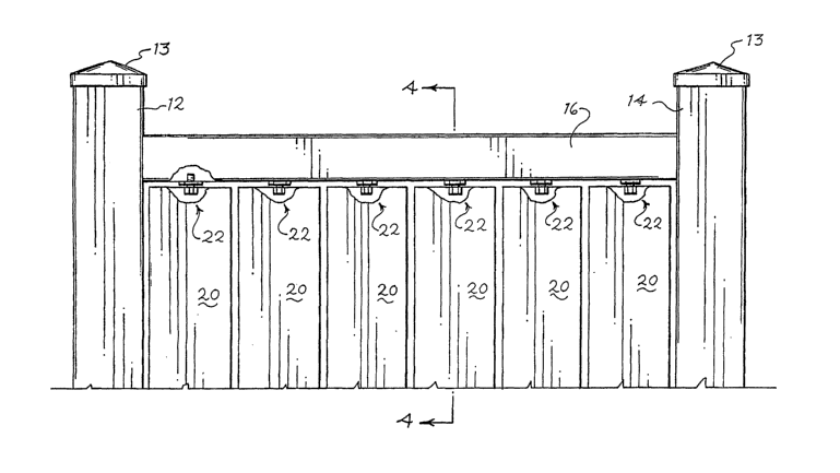
[0052] Figure 1 illustrates a front elevational view of a portion of the fence
10
constructed in accordance with the present invention. The fence 10 includes
vertical
fence posts 12 and 14 and top and bottom horizontal fence rails 16 and 18. End
caps
13 are placed on the upper ends of the supporting fence posts 12 and 14. In
the
preferred embodiments these components of the fence 10 are hollow and can be
constructed from plastic materials such as polyvinyl chloride (PVC). The
plastic
members can be injection or blow molded, or extruded, and the like.
[0053] The Fence 10 includes a series of fence members or pickets 20
positioned
between the top and bottom fence rails 16 and 18. The illustrated fence
members 20
are vertical but the members can be arranged horizontally, diagonally or in
other
positions that may be desired. These fence members or pickets 20 can be
selectively
and readily adjusted to change the use, function, or appearance of the fence
10.
[0054] Figures 1 and 2 illustrate the fence members 20 being positioned in
several
different orientations for illustrative purposes. As seen in Figure l, each
fence
member 20 is movably supported on the upper fence rail 16 by an upper support
CA 02513766 2005-07-20
WO 2004/067881 PCT/US2004/000636
structure 22 and supported on another rail 18 by an additional support
structure 24.
The illustrated fence includes two rails but it will be appreciated that
additional rails
can be provided on the fence.
[0055] Figures 3 and 4 illustrate the detailed construction of one embodiment
for
the upper support structure 22 for each of the fence members 20. As seen in
Figure 4, this upper support structure 22 includes a threaded fastener 26
which is
secured by a friction fit, adhesive or other suitable means to an aperture
provided in
the top of the fence member 20. One end portion of the fastener 26 can talee
the form
of a hex-head 26A and the other end of the fastener includes a threaded
portion 26B.
The fastener 26 can be provided with an aperture 28 which provides a channel
through which components such as electrical wiring, fluid or air lines or the
like can
be extended to communicate between the inside hollow portions of the rail 16
and
the fence member 20.
[0056] The fence rail 16 is provided with an aperture which receives the
threaded
end 26B of the fastening member 26, as illustrated in Figure 4. The upper
support
structure 22 also includes a threaded locking nut 27 designed to engage with
the
threaded portion 26B of the fastener 26. The locking nut 27 is preferably hex-
shaped
so that it can be rotated manually or by using a conventional wrench or other
tool to
raise or lower the locl~ing nut 27 on the fastener 26. Rotation of the member
20 is
permitted when the locking nut 27 is spaced from the upper rail 16. The nut 27
may
be used to lift the member 20 for rotation. This arrangement for the upper
support
structure 22 permits the fence member 20 to be rotated about a vertical axis
by
rotation of the fastener 26B within the aperture in the rail 16 and the
resulting
rotation of the fence member 20 with respect to the rail 16. The locking
member, as
shown in Figure 4, is placed between the fence member 20 and the end rail 16
on the
fastener 26.
[0057] Once the fence member 20 is positioned in the desired location through
the rotation about the vertical axis, the locking nut 27 can be advanced on
the
threaded portion 26B of the fastener 26 against the rail 16 to releasably lock
the
fence member 20 in the selected position. If it is later desired to move the
fence
CA 02513766 2005-07-20
WO 2004/067881 PCT/US2004/000636
member 20 into a different selective position, the locking nut 27 can be
rotated to
release the fence member 20 and permit the member to once again rotate with
respect
to the rail 16. In this manner, the fence member 20 can be moved into a
variety of
orientations between the upper fence rail 16 and the lower fence rail 18 to
adapt the
fence for performing additional functions or to give the fence a different
appearance.
[0058] Figures 5 through 9 illustrate a second embodiment for the upper
support
structure associated with each of the fence members 20. In this embodiment,
the top
end of each hollow fence member 20 is provided with an end cap 28. This end
cap
28 is held in place by a friction fit, adhesive or other suitable means, and
includes a
tab 30 which can be used to move the fence member 20 for rotation. The tab 30
is
preferably positioned on the inside face of the fence member 20 to enhance the
security provided by the fence. The end cap 28 also carries a plunger housing
32
which receives a spring loaded plunger 34 having a compression coil spring 39,
as
shown in Figures 8 and 9. A pin 29 within the housing 32 retains the spring 39
in
place. A base portion 36 has a circular element 38 and a shoulder 36A. The
plunger
34 fits within the housing 32. The circular element 38 is rotatably positioned
in an
aperture in the lower part of the rail 16 and allows the member 20 to be
rotated with
respect to the rail. Flange 36B on the plunger base 36 retains the base 36 in
place
within the plunger housing 32. The shoulder 36B engages the top rail 16 so
that the
spring 39 urges the member 20 downwardly and releasably secures the member in
a
selected position by cooperating with the lower support structure 24 of the
fence in
accordance with this invention. As shown in Figure 9, an aperture 35 can be
provided in the center of the plunger assembly 34 to define a passage for
wires or
fluid lines or the like and thereby permit communication between the fence
member
20 and the hollow rail 16. The fence member 20 can be formed to be hollow or
have
an opening to receive the wires, fluid lines or other objects.
[0059] Figures 10 through 12 illustrate a third embodiment for the upper
support
structure usable in the fence assembly in accordance with this invention. In
this
embodiment, the upper end of the fence member 20 is provided with a pivot pin
40
and the adjacent lower portion of the upper fence rail 16 is provided with a
CA 02513766 2005-07-20
WO 2004/067881 PCT/US2004/000636
collapsible tensioning member 42. Preferably, the width of the tensioning
member
42 is selected to be at least substantially the same as the width of the
fencing member
20, as shown in Figure 10. Alternatively, the tensioning member 42 can extend
along the length of the rail 16 and can be attached to or formed on the rail.
In this
manner, the open space between the fence member 20 and the rail 16 is closed
by the
tensioning member 42. The member 42 will thus improve the privacy or
protection
provided by the fence 10. The lower portion of the tensioning member 42 is
provided with an aperture 44 to receive the pin 40, as shown in Figures 11 and
12.
[0060] In accordance with this embodiment of the invention, the tensioning
member 42 is constructed from a pliable material such as flexible plastic or
elastomeric material. With this construction, the tensioning member 42 will
flex and
allow the fence member 20 to be moved against the biasing force of the
tensioning
member 42. When a moving force is applied to the fence member 20, the
collapsible
tensioning member 42 allows the member 20 to be rotated into the desired
position.
The member 42 then applies a tensioning biasing force to the member 20 to
releasably secure the fence member 20 in the selected position.
[0061] Figures 13 through 15 illustrate a design for a second support
structure 24
for each of the fence members 20 in accordance with the present invention. One
component of the illustrated lower support structure comprises an insert 50
designed
to be fixed by suitable means to the adjacent end of each fence member 20. The
insert 50, as shown in Figure 13, includes a pivot pin 52 positioned in the
central
portion of the insert. This pin 52 preferably has a tapered end 54 to
facilitate the
guiding of the pin 52 into place. The insert 50 further includes detent
members 56
which are spaced about the periphery of the pin 52 as shown in Figures 13 and
14.
These detent members 56 have a selected shape and are positioned around the
pin 52
in a uniform pattern. In the illustrated embodiment shown in Figure 14, the
detent
members 56 comprise a plurality of radial extensions spaced uniformly 60
degrees
apart around the periphery of the pin 52. The pin 52 can also include an
aperture 55
defining a passage for wire or fluid or air lines or the like which can be
extended
CA 02513766 2005-07-20
WO 2004/067881 PCT/US2004/000636
11
between for communication between the interior of the fence member 20 and the
interior of the lower rail 18.
[0062] Figure 15 illustrates alternative configurations for the lower rail 18
of the
fence 10 in accordance with the present invention. The upper portion of the
rail 18 is
provided with an indexing and locking aperture 58A configured to receive the
pin 52
and engage with detent members 56 on the lower support structure 50. Several
alternative locking apertures 58B-E are also illustrated in Figure 15. Each of
these
apertures 58A-E have a periphery with a selected pattern of detent surfaces
60A-E
designed to cooperate with complementary detent members 56 on the lower
support
structure 50. The detents 56 can be arranged to be a selected number of
degrees
apart around the periphery of the pin 54 to be compatible with the
corresponding
shape of the aperture 58A-E and the detent surfaces 60A-E. Locking aperture
58A is
compatible with the detent members 56 in the illustrated embodiment. The
particular
configuration for the detents 56 and the corresponding peripheral apertures 60
in the
openings 58A-E can be chosen to provide a selected number of fixed positions
for
the adjustable fence member 20. The illustrated detents 56 and the apertures
60A are
positioned 60 degrees apart. If the lower support structure is to be
retrofitted to an
existing fence the apertures 58A-E can be provided on a separate member that
can be
fastened to the fence rail.
[0063] The lower support structure 50 shown in Figures 13-15 is usable with
any
of the above-described embodiments of the upper support structure 22 to
provide the
fence 10 with support means which permits each fence member 20 to be
adjustably
positioned and releasably retained in a selected position with respect to the
fence
rails 16 and 18. If the infinitely variable support structure shown in Figure
37 is used
the lower support structure would be simplified as shown in Figure 38.
[0064] If the upper support structure 22 shown in Figures 3 and 4 is used, the
locking member 27 is rotated downwardly away from the upper fence rail 16.
This
will permit the fence member 20 to be raised and rotated with respect to the
rail 16
and the lower rail 18 to the selected orientation. The member 20 rotates on
the pin
52 until the member 20 is in the desired position, and the corresponding
detent 56 is
CA 02513766 2005-07-20
WO 2004/067881 PCT/US2004/000636
12
in place within the locking aperture 58A-E on the bottom rail 18. The locking
member 27 then can be advanced on the thread 26B against the top rail 16 to
limit
the upward movement of the member 20 and lock the fence member 20 in the
selected location.
[0065] If the embodiment for the upper support structure comprises the spring
plunger 34 shown in Figures 5 through 9, or the collapsible tensioning insert
42
shown in Figures 10 through 12, the adjustment of the associated fence member
20 is
accomplished by gripping the tab 30 on the fence member 20 and applying a
moving
force. This force will act against the bias of the spring loaded plunger 34
shown in
Figure 8, or against the collapsible tensioning member 42 shown in Figures 10-
12 to
permit the fence member 20 to be rotated into a selected position. Once the
member
20 is in the desired position, release of the tab 30 will permit the bias of
the plunger
34 or the collapsible tensioning member 42 to apply a biasing force to the
fence
member 20.
[0066] The lower support structure 50 on each fence member 20 operates in
essentially the same manner as described above for each embodiment of the
upward
support structure. In each embodiment, the force of gravity and the weight of
the
fence member 20, assisted in some embodiments by a downward biasing force,
will
cause the detents 56 to be captured by the corresponding compatibly configured
recesses 60A-E in the indexing and locking aperture 58A-E. The engagement
between the detents 56 and the corresponding apertures 60A-E will releasably
lock
the associated member 20 in place. If the fence member 20 is to be adjusted
further,
the upward lifting force on the member 20 will disengage the detents 56 from
the
associated recesses 60A-E of the apertures 58A-E in the lower rail 18. The
fence
member 20 can then be rotated into a desired position and released. Gravity,
assisted
by a biasing force, will re-engage the detents 56 with the appropriate
recesses 60A-E
in the lower rail 18 to once again releasably lock the fence member 20 in a
desired
location.
[0067] The fence members 20 including the support structures described above
therefore can be adjusted to change the function, use or appearance of the
fence 10.
CA 02513766 2005-07-20
WO 2004/067881 PCT/US2004/000636
13
If maximum security or privacy and minimum visibility through the fence are
required, each of the fence members 20 can be positioned to be essentially
parallel
with the upper and lower fence rails 16 and 18. In the embodiment shown in
Figures
10-12, the upper support structure including the collapsible tensioning member
42
will close the space between the upper portion of the member 20 and the upper
rail
16 to further reduce the visibility through by the fence 10. Alternatively,
each fence
member 20 can be individually or collectively adjusted into any selected
position
with respect to the fence rails. For example, if a position of 60 degrees for
the fence
members 20 would be desired to respond to the effect of the sunlight or wind,
provide privacy or perform other uses, one or all of the individual fence
members 20
can be adjusted to that selected angle as described above and locked into
place.
[0068] Figures 16-18 illustrate another aspect of the present invention which
allows the components of the fence 10 such as the posts, rails or pickets or
fence
members to be varied in appearance or changed in function in a different
manner. In
this embodiment, each fence member 20 is provided on one or more of its faces
with
adhering or gripping elements. In the illustrated embodiment the gripping
elements
comprise a pair of channels 70, as clearly shown in Figures 16 and 17. These
channels 70 are preferably formed in place when the member 20 is manufactured
from a plastic material such as PVC. In Figures 16 and 17, each channel 70 is
positioned along the edge of a face of the member 20 and forms a groove 72
along
each edge. The gripping elements may also comprise grooves formed within the
sides of the fence members 20. As shown in Figure 17, a separate member such
as a
panel member 74 can be inserted into the grooves 72. The panel 74 will be
removably held in place along each side of the fence member 20 by the channels
70.
A suitable detent can be provided to prevent the panel 74 from sliding out of
the
channels 70.
[0069] The panel 74 is selected to have a color, texture or shape different
from
the color or texture of the associated fence member 20. If the fence member 20
is
formed from a plastic material such as PVC, the usual color for the fence
member is a
light or white color. The changeable panel member 74 can be made from a
material
CA 02513766 2005-07-20
WO 2004/067881 PCT/US2004/000636
14
such as vinyl sheeting, and selected to change the color or texture of the
member 20.
The panel 74 also provides additional protection for the fence member 20 such
as
protection from ultraviolet rays.
[0070] Vinyl sheeting, such as used in vinyl siding for homes, is very useful
for
forming the separate panel members 74. Vinyl sheeting is readily available in
a
variety of colors and textures, and can be economically formed or sized to be
positioned on outdoor structures of different dimensions. The use of vinyl
sheeting
to change the appearance or texture of an outdoor structure in accordance with
this
invention results in substantial economic and manufacturing benefits. The need
to
manufacture and inventory a substantial number of structures or components of
varying colors and textures is reduced. Instead, the basic components of a
structure
such as a fence can be modified by providing a supply of readily available and
economically manufactured vinyl sheets of different colors or textures.
[0071] Figure 18 shows a fence system similar to the system shown in Figure 1
but modified to include inserts 75A-75F on the faces of the fence members 20.
For
illustrative purposes, each insert 75A-75F is shown in Figure 18 as having a
different
color, e.g., green, yellow, blue, orange, brown and silver, respectively. The
fence
panels could also comprise solar panels 90, as shown in Figure 21, or panels
having a
selected texture. As noted above, these changeable panels can be selected for
a
variety of purposes, such as to change a portion of a fence to match the color
of a
nearby house, to reflect holidays or changes in seasons for providing the
fence with
decorative patterns, to display messages, to collect solar energy, or for
other uses.
[0072] Figures 19 through 21 illustrate further embodiments of the system for
changing the appearance or function of the fence 10 in accordance with this
invention. In Figure 19, a generally u-shaped channel member 80 is designed to
be
retrofitted onto an existing fence member 20. The channel member 80 can be
adhered to the face of the member 20 by a suitable adhesive, or held in place
by other
forms of fasteners. The channel member 80 defines a channel 82 at each edge of
the
member 20 which creates grooves 84.
CA 02513766 2005-07-20
WO 2004/067881 PCT/US2004/000636
[0073] Figure 20 illustrates the fence member 20 in Figure 19 having a channel
member 80 joined to its face and further having an insert member 89 positioned
in
place in the grooves 84. This channel member 80 and/or the insert member 89
can
have a different color, texture or shape as compared to the appearance and
material
forming the fence member 20. Each fence member 20 including the channel member
80 can be changed by selecting the inserts 89 to suit the particular use or
appearance
desired for the fence member. Other inserts such as the panels 74 or the solar
panel
90 shown in Figure 21 can be inserted within the channel member 80.
[0074] Figure 21 illustrates a further aspect of the present invention where
the
structure inserted onto the face of the fence member 20 comprises a solar
energizing
element or laminate such as a solar panel 90. In this embodiment each of the
fence
members 20 that carry a solar panel 90 will be capable of collecting solar
energy
from the sunlight. The above-described upper and lower adjustable supports for
each fence member 20 can be used to position the fence members 20 to maximize
the
effectiveness of the solar panels 90 in response to the changes in seasons, or
to
accommodate other changes in environmental conditions. Suitable conducting
wires
or fittings and connectors can be included in the structure to distribute the
energy
collected by the solar panels 90. For example, electrical wires 91 can be
connected
to the solar panel 90 and extended through suitable holes in the fence member
20.
The wires 91 can be connected to other wires, fittings or connectors. in the
fence
system
[0075] The embodiments of the invention shown in Figures 16-21 can be used to
change the appearance of the fence member 20 for a variety of purposes. As an
example, the structure can be used to change a normally white fence to a
darker color
that matches or complements the color of the associated house or other
structure.
The fence member 20 can be changed in appearance to reflect the seasons or
holidays or other events important to the user. Alternatively the panels 74
can added
to the fence member 20 to carry a message such as an advertisement. Other
functions, such as the collection of solar energy by the solar panels 90, can
be added
to the fence.
CA 02513766 2005-07-20
WO 2004/067881 PCT/US2004/000636
16
[0076] The embodiments of the invention illustrated in Figures 16 through 21
can
also be used in other outdoor structures such as railings or deck members or
the like
to change the appearance, color, texture or function of the structure. The
insert
panels 80 and 90 can be used to produce the desired change to the rail or the
deck
member.
[0077] Figure 22A illustrates an improved fence rail 100 which can be
incorporated into a fence. This fence rail 100 can be used as a replacement
for the
top fence rail 16 or the bottom fence rail 18. The fence rail 100 can be made
from
plastic such as PVC. The rail 100 is manufactured, such as by molding or
extrusion,
to have multiple compartments such as a lower compartment 102 and an upper
compartment 104. Both of these compartments 102 and 104 preferably extend for
the length of the rail 100. In an alternative embodiment the compartment 104
can
include a vertical divider 105, as shown in dotted lines in Figure 22A. This
divider
105 forms a plurality of compartments and adds strength to the rail. One side
of the
lower compartment 102 in this embodiment is provided with an access opening
106.
This access opening 106 is also formed into the rail 100 and also preferably
extends
for the length of the rail. The access opening 106 provides the fence rail 100
with an
opening for receiving attachment devices such as the hanger 108 or the like,
as
shown in Figure 22A. The hanger 108 or other suitable fastening device can be
inserted within the access opening 106 and used to support a variety of items
on the
fence rail 100. The hanger 108 or other suitable devices can be received
within the
opening 106 for supplying decorative items, outdoor gardening or cooking
implements, support surfaces for flower pots, garden hose supports, and the
like.
[0078] The access opening 106 in the rail 100 further provides access to the
lower
compartment 102. The compartment 102 therefore can receive through the opening
106 additional items such as electrical wires or conduits that would desirably
be
contained within the compartment 102 along the length of the rail 100.
[0079] The upper portion of the rail 100 as illustrated Figure 22A includes an
openable top 110. This top 110 can be joined to the rail 100 so that a
flexible hinge
joint 112 one end of the top 110 to the rail 100. The top 110 can be moved
about the
CA 02513766 2005-07-20
WO 2004/067881 PCT/US2004/000636
17
hinge 112, as shown by the arrow in Figure 22A to open and close the
compartment
104. The outer end of the top 110 includes a first latch element 114 which is
dimensioned to engage and be retained by a compatible second latch element 116
provided on the adj acent top portion of the rail 110. The latch elements 114
and 116
can be releasably engaged by moving the top 110 downwardly to bring the latch
elements 114 and 116 into engagement. In this manner, the compartment 104 of
the
rail 100 can be selectively opened and closed and is readily accessible for
use.
[0080] By this arrangement, items such as water hoses, air lines or electrical
wires can be placed within the upper compartment 104 through the opening
created
by the opened top 110. After the object is in place, the top 110 can be closed
by
engaging the locking elements 114 and 116. The upper compartment 104 can be
used to store items and create pathways for larger items such as electrical
wires or
hoses which would not readily fit within the access opening 106 of the lower
portion
102. Moreover, the compartments 102 and 104 in the rail 100 can be used to
separate items such as electric wires and water lines as desired. The conduits
or
wires provided within the compartments 102 or 104 of the rail 100 can be
connected
to similar components in other parts of the fence such as the fence members 20
through the apertures described above.
[0081] Figure 22b shows a modified fence rail 100B which includes lower and
upper compartments 102B and 104B and an access opening 106B. The upper
compartment 104B in this embodiment of the rail 100 is closed. The lower
compartment 102B is accessible through the opening 106B, as shown in Figure
22B.
The closed upper compartment 104 provides the rail 100 with increased rigidity
and
stiffness. At the same time, the access opening 106B permits the rail 100 to
receive
appliance hangers such as the hanger 108 shown in 22A, or other items. As
discussed with respect to the embodiment in Figure 22A, the opening 106B can
also
receive items such as wires or other conduits within the compartment 102B.
[0082] Figure 23 illustrates a third embodiment for a rail. In this embodiment
the
rail 120 is provided with a single enlarged compartment 122. A movable top 124
is
attached to the rail 120 by a flexible hinge 126. As described above with
respect to
CA 02513766 2005-07-20
WO 2004/067881 PCT/US2004/000636
18
the embodiment of Figure 22A, the upper portion of the top member 124 includes
a
latch element 128 which is adapted to engage with a mating latch element 129
on the
rail 120. The rail 120 can be opened and closed by engaging or disengaging the
latch
elements 128 and 129. The compartment 122 is readily accessible to receive
larger
items such as larger water hoses, electrical wires, or the like. The
compartment 122
in this embodiment also can be sufficiently large to act as a storage
compartment.
[0083] Figure 24 illustrates a still further embodiment of an improved rail
130.
The fence rail 130 has reinforcing ribs 132 in the rail to provide rigidity or
stiffness.
The upper portion of the rail 130 defines a compartment 134 for receiving
items such
as hoses, electrical wires or air lines, or for storage purposes. As described
with
respect to the embodiment shown in Figures 22A and 23, the upper portion of
the rail
130 includes a top 136 which is connected by a flexible hinge 137 to the body
of the
rail 130. Latch elements 138 and 139 are provided to releasably secure the top
136.
[0084] Figure 25 illustrates a rail embodiment 140 which includes conduits 141
and 142 integrally formed within the rail. The conduits 141 and 142 are
positioned
in the lower portion of the rail and extend the full length of the rail. These
conduits
141 and 142 can provide integrated passageways for fluids such as air or
water, or
for other items such as electrical wires. The upper portion of the rail 140
defines a
compartment 144. A top 146 is connected by a flexible hinge 147 to the rail
140.
The outer end of the top portion 146 includes latching element 148 which
cooperates
with a compatible latch element 149 on the rail 140. The compartment 144 is
thus
readily accessible by means of opening or closing the top portion 146.
[0085] Figure 26 shows another embodiment of a fence rail 150 with passages
laid in place within the rail. The plurality of smaller passageways 151 are
adapted to
form conduits or to receive smaller items such as electrical wires. A larger
integral
passageway 152 forms a larger conduit or can receive larger wires or the like.
Access to the upper portion of the rail 150 is permitted by the movable top
portion
156 which provides access to the upper compartment 154 by means of a flexible
integral hinge 157. Latching elements 158 and 159 on the adjacent ends of the
rail
150 and the top 156 permit easy access to the top compartment 154.
CA 02513766 2005-07-20
WO 2004/067881 PCT/US2004/000636
19
[0086] Figure 27 illustrates a fence system incorporating the above-described
adjustable fence members, such as described above with respect to Figures 1-3,
in
combination with an improved fence rail 100 as shown in Figure 22A. The fence
rail
100 is supported between fence posts 12 and 14 and, in turn, provides upper
support
for each of the adjustable fence members 20. The access opening 106 in the
fence
rail 100 permits attachments such as the hanger 108 to be added to the fence.
The
access 106 also would permit items such as electrical wires to be placed
within the
lower compartment 102 of the rail 100, as shown in Figure 22A. Similarly, the
openable top portion 110 of the fence rail 100 provides ready access to the
upper
compartment 104. The compartment 104 could also be provided in another lower
rail of the fence. In this maimer, items can be stored in a rail of the fence,
or the rail
compartment 104 can be used to place items such as electrical wires, water or
air
lines along the length of the rail 100.
[0087] In Figure 28, the top fence rail 100, having a construction such as
shown
in Figure 23 , has a top 124 which permits a compartment 122 which could be
selectively opened and closed. This compartment 122 in this embodiment
contains a
series of insertable containers 112 adapted to support items such as floral
arrangements, or bird seeders, or the like. A plurality of these containers
can be
stationed along rail 100 in the compartment 122 to provide the fence structure
with
containerized materials such as floral arrangements, bird feeders. Insect
repellants,
net systems or the like,
[0088] Figures 29-31 illustrated further the embodiment of the invention where
an existing fence structure is retrofitted to have a rail including an
accessible
compartment. In this embodiment a fence system including fence members 20
supported on upper and lower rails 16 and 18 by fence post 12 and 14 is
provided
with a retrofit elongate rail 120. As shown in Figures 29-31 rail 120 is
extended
laterally along the fence system and supported by the fence posts 12 and 14.
Alternatively, the rail 120 can be supported by the preexisting fence rail 16.
This
fence rail 120 is similar to the rail having an accessible compartment such as
shown
CA 02513766 2005-07-20
WO 2004/067881 PCT/US2004/000636
in Figures 22A-26. The rail includes a movable cover 122 which can be opened
and
closed to provide ready access to the compartment 124 within the rail. As
described
above, the compartment provided in the rail 120 can receive a variety of obj
ects such
as wires, fluid lines, floral containers and the like.
[0089] The embodiment of the fence system shown in Figures 32 and 33 provide
the fence with a device to raise or extend the fence to suit particular needs
or
functions. For example, the extension mechanism 130 can be used if the area
near
the fence is being used for a game to keep balls or other items within the
fenced area.
Additional screening can also be used in place of the net 132 to enhance the
privacy
of the fence.
[0090] Figures 34 and 35 show a universal attachment mechanism that can be
incorporated into the fence system of this invention. In this embodiment, the
compartment 104 within the fence rail 100 (with top 110 being removable if
desired)
is used to receive and support an attachment mechanism 140. The mechanism 140
can be dimensioned to fit securely within the compartment 104 and can extended
for
a selected length along the rail 100. Grooves or retaining surfaces 142 can be
provided to engage with the upper portions of the rail 100 and assist in
securing the
mechanism 140 in the rail. The upper portion of the mechanism 140 can be
dimensioned to extend out of the compartment 104 in the rail 100, as seen in
Figures
34 and 35 to support attachments.
[0091] Fastening grooves or recesses 144, 146 and 148 are provided in the top
portion of the mechanism 140. These recesses 144, 146 and 148 can be different
sizes or shapes and are designed to receive corresponding fastening elements
on
items which can be connected to and supported by the fence rail 100. For
example, a
working surface or table 150 can be joined in the recess 146 and a support
hook 152
can be connected in the recess 148. Other items with compatible fastening
elements
can be added to the fence rail 100 by use of this universal attachment
mechanism
140.
CA 02513766 2005-07-20
WO 2004/067881 PCT/US2004/000636
21
[0092] Figure 36 illustrates a modified rail that also can be used when it is
desired to perform functions such as collect solar energy, display signs or
the like on
the rail or change the color or texture of the rail. Figure 36A shows a
perspective
view of a triangular rail 160 which includes two angled upper surfaces.
Gripping
elements 162 are positioned on each corner of the rail 160 for receiving
panels 164.
These panels 164 can be made to have a selected color or texture, or can carry
a
message such as an advertisement. In addition panels 164 can comprise solar
panel
or laminate to collect solar energy. The angled upper surfaces of this
triangular rail
160 makes the panels very visible and positions a solar panel 164 for more
exposure
to the sun.
[0093] Figures 37, 37A and 38 illustrate a modified support structure for use
in
an adjustable fence in accordance with this invention. As seen in Figure 37
one end
of a fence member 20 is provided with an infinitely variable support structure
170
including a pivot pin 172. One end of the pin 172 is fixed in the fence member
20 by
a head 174. The other end extends into a positioning clamp assembly 176. The
clamp assembly 176 pivotally receives the pin 172 and is fixed within the
adjacent
fence rail 16. A flexible clamping ring 178 on the clamping assembly surrounds
the
pin 172 and includes a fastener such as the threaded bolt 180. This ring 178
is
connected to or integral with the assembly 176. Figure 38 shows a suitable
pivot pin
182 that is positioned in the other end of the fence member 20 and allows the
member to rotate with respect to the associated rail.
[0094] The arrangement for the variable support structure 170 shown in Figures
37, 37A and 38 can be used to move the fence member 20 into a plurality of
selected
positions with respect to the rail 16 by pivoting the member about the pins
172 and
182. Once the member 20 is in the desired position the bolt 180 can be
advanced to
tighten the clamp 178 around the pm 172. Since the clamp 178 is fixed to the
rail 16
through the clamp assembly 176, this clamping force will releasably secure the
fence
member in the selected position. An infinite number of positions are possible
for the
member 20 as a result of this embodiment for the support structure.
CA 02513766 2005-07-20
WO 2004/067881 PCT/US2004/000636
22
[0095] As described above, the support structures for the fence members 20
include apertures that can be used in combination with the compartments 102 or
104
in the top rail 100 to connect the fence members 20 with electrical wiring, or
with
conduits for receiving water or the life. The fence members 20 can further
include
inserts, such as the panels 74 or the solar panels 90 which can be connected
to wiring
in the rail 100. The functions of the fence 10 are substantially enhanced by
the
combined use of the features of this invention
[0096] The features and functions of the improved rails illustrated in Figures
22
through 26 can be adapted for use with other structures, such as hand rails or
decl~ing. Such structures would thereby be provided with accessible
compartments
and passageways for receiving items, such as wires or conduits, which enhance
the
function of the structure.
[0097] It is therefore intended that the foregoing detailed description be
regarded
as illustrative rather than limiting, and that it be understood that it is the
following
claims, including all equivalents, that are intended to define the spirit and
scope of
this invention.