Note: Descriptions are shown in the official language in which they were submitted.
CA 02513880 2005-07-20
WO 2004/065010 PCT/US2004/001639
METHOD AND SYSTEM FOR MICROFLUIDIC MANIPULATION,
AMPLIFICATION AND ANALYSIS OF FLUIDS, FOR EXAMPLE, BACTERIA
ASSAYS AND ANTIGLOBULIN TESTING
CROSS-REFERENCE TO RELATED APPLICATIONS
This application claims the benefit of U.S. Provisional Patent
Application Nos. 60/441,906, filed January 21, 2003, and 60/441,373, filed
January 21, 2003, both of ~nrhich are hereby incorporated by reference in
their
entirety.
BACC~GROUiIID OF TFIE Ii~~E~ITION
Field of the Invention
The present invention relates generally to microfluidic devices and
analysis methods, and more parkicularly, to microfluidic devices and methods
for the manipulation, amplification and analysis of fluid samples including,
for
example, blood platelet bacteria assays and antiglobulin testing'.
Descripfiion of the Related Art
Microfluidic devices have become popular in recent years for
performing analytical testing. Using tools developed by the semiconductor
industry to miniaturise electronics, it has bec~me possible to fabricate
infiricate
fluid sysfiems fihafi can be ine~zpensively mass-produced. Sysfiems have been
~0 developed fio perfi~rm a variefiy of analyfiical fiechnig~aes f~r fihe
aca~uisifiion and
pr~cessing ~fi inf~rmafiion.
CA 02513880 2005-07-20
WO 2004/065010 PCT/US2004/001639
The ability to perform analyses microfluidically provides
substantial advantages of throughput, reagent consumption, and automatability.
Another advantage of microfluidic systems is the ability to integrate a
plurality of
different operations in a single "lap-on-a-chip" device for performing
processing
of reactants for analysis and/or synthesis.
Microfluidic devices may be constructed in a multi-layer laminated
structure wherein each layer has channels and structures fabricated from a
laminate material to form microscale voids or channels where fluids flow. A
microscale or microfluidic channel is generally defined as a fluid passage
which
~0 has at least one internal cross-sectional dimension that is less than 500
tam and
typically between about 0. ~ tam and about 500 pam.
U.S. Patent i~o. 5,7~G,352, which patent is hereby incorporated
by reference in its entirety, is an example of a microfluidic device. The '352
patent teaches a microfluidic system for detecting the presence of analyte
~ 5 particles in a sample stream using a laminar flow channel having at least
two
input. channels which provide an indicator stream and a sample stream, where
the laminar flow channel has a depth sufficiently small to allow laminar flow
of
the streams and length sufficient to allow diffusion of particles of the
analyte
into the indicator stream to form a detection area, and having an outlet out
of
20 the channel to form a single mixed stream. This device, which is known as a
T-
Sensor, allows the movement of different fluidic layers next to each other
within
a channel without mia~ing other than by difFusion. A sample stream, such as
~~hole blood, a receptor stream, such as an indicator solution, and a
reference
stream, v~,~hich may be a hn~c~n analyte standard, arcs introduced into a
comm~n
25 microfl~aidic channel ~eithin the T-Sensor, and the streams fl~w neat to
each
other until they e~zit the channel. Smaller particles, such as ions or small
proteins, diffuse rapidly across fhe fluid boundaries, whereas larger
molecules
diffuse more slowly. Large particles, such as blood cells, show no significant
diffusion within the time the two flow streams are in contact.
30 Typically, microfluidic systems require some type of external
2
CA 02513880 2005-07-20
WO 2004/065010 PCT/US2004/001639
fluidic driver to function, such as piezoelectric pumps, micro-syringe pumps,
electroosmotic pumps, and the like. However, in U.S. Patent Application No.
09/684,094, which application is assigned to the assignee of the present
invention and is hereby incorporated by reference in its entirety,
microfluidic
systems are described which are completely driven by inherently available
internal forces such as gravity, hydrostatic pressure, capillary force,
absorption
by porous material or chemically induced pressures or vacuums.
In addition, many different types of valves for use in controlling
fluids in microscale devices have been developed. For example, U.S. Patent
~0 No. 6,432,22 describes one-way valves for use in laminated microfluidic
structures, U.S. Patent No. 6,581,899 describes ball bearing valves for use in
laminated microfluidic structures, and U.S. Patent Application No.
~0/~~4.,890,
which application is assigned to the assignee of the present invention,
describes a pneumatic valve interface, also known as a zero dead volume
~ 5 valve, for use in laminated microfluidic structures. The foregoing patents
and
patent applications are hereby incorporated by reference in their entirety.
Although there have been - many advances in the field, there
remains a need for new and improved microfluidic devices for manipulating,
amplifying and analyzing fluid samples.
20 ~ne example of an area needing new and improved microfluidic
devices is with respect to bacterial and antiglobulin analysis. Bacterial
sepsis
caused by bacterially contaminated platelets is the cause of blood transfusion
transmitted infections up to 250 times more often than HI~, hepatitis ~ or
l~Aest
mile virus. ~f thc~ ~. milli~n platelet units transfused each year in the
United
25 States, x,000 to 4,000 are contaminated with bacteria, and ~8~ to x,000
cases
of clinical sepsis result. Twenty to q.0 percent of patients ~~ith clinical
symptoms
die.
3
CA 02513880 2005-07-20
WO 2004/065010 PCT/US2004/001639
Current platelet bacteria assays
Platelet screening is not routinely performed in the US prior to
transfusion; however, AABB has proposed a new standard requiring pre-
transfusion testing of platelets for bacterial contamination.
Several methods are currently being used outside the US:
Standard cell culture: platelets are cultured in Petri-dish, and bacteria
are detected after staining. This method is very time consuming, is
not automated, and requires a significant amount of platelets.
Pall Sacferia ~etecti~n Sysfem (Pall B~S): uses changes in oxygen
concentration as a result of bacterial growth. Since bacteria consume
oxygen, abnormally low levels of oxygen in a platelet sample indicate
the presence of bacteria.
o ~i~f~lerieux's BacT/Alert system detects the presence of bacteria by
tracking their production of carbon dioxide.
~ h~ern~sy~stern is developing a system for bacterial detection in
platelets concentrates based on fluorescence detection after bacteria
labeling with a fluorescent marker.
BRIEF SUMMARY ~F THE INVENTI~N
Aspects of the current invention include a platelet-specific bacteria
assay system for urine and whole blood analysis. This system, known as the
BAC Card system, is based on the identification of bacterial ~NA detection
through bacteria lysing and subsequent isothermal ~f~A amplifiicati~n and
detection. Yet an~ther embodiment of the present: invention provides analysis
and detection of urine to determine the presence of seazually transmitted
diseases.
The following exemplary steps are performed on the microfluidic
card according to aspects of the present invention: collect a sample from the
blood platelet bag is placed on an inlet of the lab card; lyre bacteria (as
well as
remaining white cells) in a lysing channel; capfiure bacterial ~I~A onto a
solid
4
CA 02513880 2005-07-20
WO 2004/065010 PCT/US2004/001639
substrate in the amplification chamber; pump DNA primers, designed from
genes encoding the small subunit of the RNA molecule of the ribosome (16S
rRNA or SSU rRNA genes) over the solid substrate followed by wash buffers,
as the amplification chamber is exposed to an isothermal amplification
temperature profile; pump amplified 16S rRNA DNA over a lateral flow strip;
visual indication of the presence of bacterial DNA.
Further aspects of the invention include a microfluidic system for
typing antiglobulin assays including a substrate having flow channels therein,
an inlet port for receiving a blood sample, a filter for separating red cells
and
plasma, a system for mixing a portion of the plasma with appropriate reagents,
a heating source, a port for adding antiglobulin serum, and a window for
visually
reviewing the test results.
SRIEF DESCRIPTI~N ~F THE SEVERAL lllElii~S ~F THE DRAI~IINGS
Figure 1A illustrates a schematic of a microfluidic analysis card in
accordance with principles of the present invention. Figure 1 S is a cross
section of Figure 1A along line 1 B-1 B.
Figure 2 illustrates a schematic of an instrument for actuating fluid
flow in the microfluidic analysis card according to principles of the present
invention.
Figure 3 illustrates a process flowchart for a diagnostic device
performing microfluidic antiglobulin analysis in accordance with principles of
the
present invention.
Figure 4P~ illustrates a process flowchart f~r bacteria diagnostic
devices for detecting bacteria in platelets in accordance with principles of
the
present invention.
Figure 4.S is yet another embodiment of the present inven~:ion
illustrating a flowchart for processing a bacteria diagnostic device for
protecting
bacteria in platelets in accordance with principles of the present invention.
5
CA 02513880 2005-07-20
WO 2004/065010 PCT/US2004/001639
Figure 4C is a chart illustrating the steps of the flowchart
contained in Figure 4B.
Figure 5 is a schematic of the microfluidic device in accordance of
the flowchart of Figure 4.
Figure 6 is flowchart of an exemplary bacteria assay card in
accordance with principles of the present invention.
Figure 7A and 7B are illustrations of one embodiment of the
bacteria assay card illustrating the connection port for a syringe in
accordance
with principles of the present invention.
Figure ~ is a cross-sectional view of a heat transfer rod and plate
mounted in the heater block in accordance with principles of the present
invention.
Figure 9 is a cross-section of an insulation and platen assembly in
accordance with principles of the present invention.
Figure 10 is a chart of temperature vs. time to heat the system in
accordance with principles of the present invention.
Figure 11 is a graph of temperature vs. time in accordance with
principles of the present invention.
Figure 12 is a graph of temperature vs. time in accordance with
principles of the present invention.
Figure 13 is a graph of temperafiure vs. time in accordance with
principles of the present invention.
Figure 1q. is a graph temperature vs. time in accordance v~eith
principles ofi the present invention.
~ET~41LE~ ~ES~F~IPTI~i~ ~F TF-IE ll~~El~l'I~i~
As noted previously, the present invention relates to microfluidic
devices and methods utilising a plurality of microfluidic channels, inlets,
valves,
membranes, pumps, liquid barriers and other elements arranged in various
configurations to manipulate the flow of a fluid sample in order to prepare
such
6
CA 02513880 2005-07-20
WO 2004/065010 PCT/US2004/001639
sample for analysis and to analyze the fluid sample. In the following
description, certain specific embodiments of the present devices and methods
are set forth, however, persons skilled in the art will understand that the
various
embodiments and elements described below may be combined or modified
without deviating from the spirit and scope of the invention.
As illustrated in Figures 1A and 1 B, one embodiment of the
present invention includes a disposable lab card 100 device that is a
bacterial
assay system for urine and whole blood analysis. The system includes fluid
miniaturization capabilities in order to perform lysing and ~I~A capture. ~n-
card isothermal amplification is then performed in order to detect and
identify
bacteria in a sample.
Further aspects of the present invention include a microfluidic system for
isolation and amplification of ~i~lA from aqueous solutions and detection of
the
~I~A on a strip reader, including a disposable card for use, for example, in
analysis of E. coli in water as well as analysis of sexually transmitted
diseases
(ST~). According to one aspect of the invention, the card may include an
embedded membrane that permits quantities of fluid, for example,
approximately 100 ml of water or 10 milliliters of urine, to pass through the
membrane. As fluid passes through the membrane, the membrane filters out
cells and cellular debris. Any biological debris on the membrane may be lysed
and the ~fVA amplified via PCR amplification protocol (appropriate reagents
and thermal cycling conditions). The amplified ~I~A may then be transferred to
a lateral flow detection strip f~r the diagnostic read oat.
Further aspects of the invention include a micr~fl~aidic system for
~5 typing antigl~bulin assays. Thc~ Antiglob~alin card (the ~4H~ card)
addresses the
issue that many red cell antibodies are Igf~ and do not directly agglutinate
sensitized red blood cells. ~nce These antibodies or the complement activated
by these antibodies are attached to sensitized red blood cells, they are
detected
by the addition of an anti-human globulin or an anti-complement reagent. This
7
CA 02513880 2005-07-20
WO 2004/065010 PCT/US2004/001639
embodiment includes three areas: a microfluidic separator; a room-temperature
microfluidic circuit, and a 37 degree Celsius microfluidic circuit.
Bacterial Assay Microfluidic Card
Aspects of the current invention include a platelet-specific bacteria
assay system for urine and whole blood analysis. This system, fcnown as the
BAC Card system, is based on the identification of bacterial DNA detection
through bacteria lysing and subsequent isothermal DNA amplification and
detection.
All steps are performed on the microfluidic card. As compared to
prior arh methods, the whole process of the current invention will talze a
reduced
amount of time, for e~zample, less than 90 minutes; and will have an increased
sensitivity, for example, a sensitivity of approa~imately 100 bacteria/mL. The
following include exemplary steps in the process:
~ A sample is collected from the blood platelet bag is placed on an inlet
of the lab card
Bacteria (as well as remaining white cells) are lysed in a lysing
channel
Bacterial DNA is captured onto a solid substrate in the amplification
chamber
~ DNA primers, designed from genes encoding fihe small subunit of the
f~1~~4 molecule of the ribosome (16S rf~I~A or SSU rF~I~A genes) are
pumped through over the solid substrate follo~eed by ~,~ash buffers,
as the amplification chamber is e~cposed to an is~thermal
~5 amplification temperature profile
o R~mplified 16S rl~i~~4 Di~A is then pumped over a lateral flo~,v strip,
~~here the presence of bacterial DI~A is visually indicated
Figure ~ illustrates the bacterial assay card (BAC) interfacing with
an instrumentation sysfiem X00 that may be used to operate the BAC Card 100.
3
CA 02513880 2005-07-20
WO 2004/065010 PCT/US2004/001639
Antiqlobulin (AHG) Card
Yet another embodiment of the present invention is an assay card
for Antiglobulin testing, (the AHG Card).
The AGH Card addresses the issue that many red cell antibodies
are IgG and do not directly agglutinate the sensitized red blood cells. Once
these antibodies or the complement activated by these antibodies are attached
to sensitized red blood cells, they are detected by addition of an anti-human
globulin and or anti-complement reagent.
~ 0 As illustrated in Figure 3, according to one embodiment of the
present invention, a microfluidics based card will perform all functions
required
for the AS~/Rh and AHG assay on board the card. This embodiment includes
three areas:
I, a microfluidic plasma separator
~ 5 II. a room-temperature microfluidic circuit, and
III. a 37 ° C microfluidic circuit
Areas II and III are incubated at different temperatures using a
custom heat pad incubator. The AHG Card does not require any e~cternal
pumping or detection means. Fluids are moved through the card using
20 infiegrated on-card bellows pumps as described in applicants co-pending
application filed January 14, 2004 entitled IV11CR~FLIJI~IC ~E~IICES F~R
FLUI~ iI~AI~IPULATI~N AN~ ANALYSIS, serial number not yet assigned,
herein incorporated in its entirety by reference. Results are visually
interpreted.
25 In acc~rdance ~,~ith one aspect of the present invention, and according to
the
Flov,~ Chart shoevn in Figure 3 the following steps may be performed on the
card:
9
CA 02513880 2005-07-20
WO 2004/065010 PCT/US2004/001639
1. In Area I, a whole blood sample is microfluidically
separated into red cells (Sample 1 ) and plasma (Sample 2) without
centrifugation.
2. Sample 2 is separated into two aliquots - Sample 2a and
Sample 2b. Sample 2a is moved to Area II, and Sample 2b is moved to Area III.
3. In Area II, residual plasma proteins are removed from the
red-cell rich aliquot by diffusion-based separation, and the aliquot is
diluted in
saline to a 3-5°/~ of red cells concentration. Then, in three
individual
microchannels, Sample 1 is reacted with Anti-A, Anti-S, and Anti-~ reagents,
and the reactions are visually interpreted in the reaction windows.
Concurrently,
Sample ~a is reacted in two individual microchannels with A~ and ~ red blood
cells, and the reactions are also visually interpreted.
In Area III, the card is brought to 37° C; reagents, red cells,
SI and SII (diluted red cells) are incubated for 15-60 minutes with the
plasma. If
the serum contains an antibody specific for an antigen on the red cells, the
antibody will sensitize the cells (buff not agglutinate them, if the antibody
is IgG).
The mi~eture flows through a separation medium where proteins are removed
from the Sample. After a washing step, AHG serum is added in a microchannel,
and the test results are visually interpreted.
lnlith respect to the above-mentioned steps, step 1 discusses
microfluidically separating the blood sample into red cells and plasma without
centrifugation. This may be accomplished in a number of different ~eays. In
one embodiment, a diffiusion-based separation is used as discussed in U.S.
~5 Patent fro. 5,g3Z,100 herein incorporated by reference. The differential
transport requires an e~~traction fluid that has been omitted from the above
referenced flow diagram.
In yet another embodiment, particle lift effect may be used.
Particles flowing in the microchannel flow away from the wall leaving a layer
immediately adjacent to the channel that is particle-free. This thin particle-
free
CA 02513880 2005-07-20
WO 2004/065010 PCT/US2004/001639
layer may be stripped from the fluid flow by several means including
perforating
the wall of the channel, providing vents, or similar means. The particles
continue to migrate toward the center despite stripping off various particle-
free
fluid, and so the process may be repeated by providing a flow channel in the
loop.
In an alternative embodiment, a filter may be used filtering the
particle-free fluid. Typically, when a filter is used it literally clogs with
red cells,
however, according to the present invention only a small amount of plasma is
needed to perform the operation and therefore a filter is adequate.
In yet another alternative embodiment, a means of separate the
red cells and plasma includes using a tangential flow filter. In yet another
embodiment of the separation means, sedimenfiation may be used to allow the
blood sample to settle, thus allowing the red cells to slowly settle while
taping a
thin layer off of the flop. Again, due to the small quantity of plasma
required,
sedimentafiion is a viable alternative.
In yet another embodiment of the present invention, step 3 and
step 2 may be combined such that diffusion-based separation is used to
completely remove the plasma and plasma proteins from the red cell aliquot.
Step 3 calls for the reactions of the antibodies A, ~, and D
reagents with the blood sample. These combined flows may be mixed through
diffusion, sedimentation, and coagulation as disclosed in IJ.S. Patent No.
6,136,~~~ herein incorporated in its entirety by reference.
As further illustrated in the flowchart ~n Figure 4, and in
c~mbination e~,~ith the disci~sure contained above rec~ardinc~ the blood
typing
Z5 micr~fluidic system, the steps ~utlined with respect to the anti-gl~bulin
assay
may be performed on a single card or alternatively, may be periormr~d on te~o
or
more cards. It may be advantageous, for e~cample, to remove the functions
performed in area 3 in order to provide incubation e~hile maintaining room
temperature for the functions in area ~. However, in an alternative
embodiment,
it is possible to perform all of the functions outlined in areas 1, ~, and 3
and to
11
CA 02513880 2005-07-20
WO 2004/065010 PCT/US2004/001639
provide an on-card heating element such as resistor that specifically heats
and
incubates the plasma mixture.
In this embodiment of a microfluidic diagnostic system, due to the
fragile nature of the red cells and diluted red cells known as SI and SII,
these
reagents cannot be preloaded onto the card as, for example, the antibody-A, B,
and D reagents can be.
The heating means used to bring the portion of the card
containing the plasma mixture to 37°~ may be any known heating means
include a flat metal resistor, infrared heating, radiant heating, a Pettier
heater,
liquid heating, or other appropriate means.
Bacteria Assay general Description
According to one embodiment of the current invention, the Single
Analyte Diagnostic DevicelSystem (SADD/S) permits the isolation and
amplification of DNA from aqueous sample solutions. The amplified DNA will be
transferred from the filter membrane to a lateral flow detection strip that
will be
used for a diagnostic reading.
In one exemplary use, the device/system will be used for the
isolation and amplification of DNA found in a water sample for the detection
of
bacteria including EschericMia. coli., Sfaphylocoecus aureus, Pseudomonas
aeruginosa, Salmonella spp., Staphylococcus epidermidis, Klebsiella
pnournoniae, Enlerobacler cloacae, /3-Strepfioeoccus, Serrolia rr~arce~cens,
and/or ~aeillus oorou~.
The isolation and fluidic preparation for thermal amplificati~n ~,~ill
take place on the disposable card while in place on the instrument. The card
~,~ill be removed from the instrument for the incubation required to complete
the
Di~A amplification. ~4fter incubation, the card will be returned to the
instrument
where the amplified Di~A will be transferred to the detection strip for a
diagnostic reading.
12
CA 02513880 2005-07-20
WO 2004/065010 PCT/US2004/001639
Another use for the present invention is the isolation and
amplification of DNA from urine for the detection of sexually transmitted
diseases.
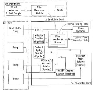
Figure 4A and 4B illustrate a schematic flowcharts illustrating
embodiments of the BAC card. Figure 4C provides a written description of
each step shown in the flowcharts of Figures 4A and 4B. Figure 4A illustrates
an embodiment having a Filter Membrane Module (FMM) that can be snapped
into the card after capturing the sample for analysis. Figure 4.B illustrates
an
embodiment having an FMM that is mounted in the microfluidic card.
The SADD system includes three major components:
o A diagnostic disposable microfluidic card which conia~ins filter
membrane that has target cells that have been filtered from
water samples, and a lateral flow detection sfirip which will be
used to detect the presence of E.coli or other bacteria in the
water samples tested;
~ An instrument supporting and controlling the fluidics on the
disposable card; and
The software that will allow instrument control to drive the
fluidics for amplification and detection.
The microfluidic card, instrument and software will be described in
further detail below.
~escri~tion of Dis~aosable f~icrofl~aidic hard
The SAD~/~ disposable microfluidic card is a multi-layer
~5 microfluidic Bard. Figures 1A, 1 B and 5 illustrate embodiments of the
microfluidic card. Figure 1A illustrates a microfluidic card 100 hawing a
membrane or filter 1 ~0 contained on the card. Also contained on the card is a
waste chamber or reservoir 130, a lateral flow detection strip 110, and
microfluidic valves 170 and microfluidic flow channels 170. The microfluidic
card 100 further may contain a port 14.0 for pipetting or otherwise dispensing
13
CA 02513880 2005-07-20
WO 2004/065010 PCT/US2004/001639
sample to the card. The microfluidic card 100 further contains microfluidic
pump
interface ports 150 in accordance with one embodiment of the present
invention. These interface ports 150 interface with the instrument system
described in further detail herein. In accordance with one aspect of the
current
invention, the microfluidic card may further contain an amplification chamber
130.
Figure 1 B is a cross section along line 1 B-1 B of the microfluidic
card of Figure 1A. Figure 1 B illusfirates exemplary locations within the
thickness of the card of various components of the card. IVlicrofluidic flow
channels 170 are positioned at various heights in the card so to interFace
with
valves, reservoirs and ports. ~ptional input port 140 extends to and opens to
an ea~terior of the card surface. Reservoirs, lateral flow strips, floew
channels,
valves and the lil~e are contained within the microfluidic card.
Figure 5 is another embodiment illustrating a microfluidic card 100
having a membrane or filter 120 contained on the card. Also contained on the
card is a waste chamber or reservoir 130, a lateral flow detection strip 110,
microfluidic reservoirs 520, 522, 524, 526, microfluidic flow channels 170,
and
an amplification chamber or reservoir. The microfluidic reservoirs 520, 522,
524, 526, may for example contain series II lysing, NASBA without enzymes,
NASBA with enzymes, an induction solution, detection solution, wash solution,
or other appropriate materials.
Figure 6 shows an illustratie~e schematic example of a~ microfluidic
card containing multiple independent systems for collection, lysing,
~~eashing,
amplification and detecti~n of a fluid sample in accordance Keith principles
of the
present invention.
Figures 7~4 and 7B illustrate yet another eazample of a microfluidic
card 700 according to principles of the present invention further including an
inlet port 710 in the microfluidic card 700. A syringe 720 is shown in Figure
7B
for introducing the liquid sample to the microfluidic card. Alternatively, a
pipette
or other appropriate device may be used. In one embodiment, the outlet 730
14
CA 02513880 2005-07-20
WO 2004/065010 PCT/US2004/001639
for the syringe 720 is configured to mate with the inlet port 740 of the
microfluidic card 700.
The BAC card may consist of the following components in
accordance with one embodiment of the present invention:
Laminate Layers: The layers are micro-machined laminates to
facilitate coordinated flow through the cards as prescribed. The assembled
laminates will form a card that is approximately 3.25 inches x 2.5 inches in
size.
The card thickness will vary depending on the number of layers.
Lateral Flow Strip: The lateral flow sfirip will be embedded into the
card laminate structure to facilitate the detection of isolated and amplified
~i~A
of the target cells. ~ne exemplary detection strip is 1.25 mm thick (.050
inch)
and approa~imately 2.5 - 3.0 mm wide by 25 mm in length.
Solution Reservoirs: Five solution reservoirs are on card to allow
the user to pipette onto the card the solutions for isolation, detection and
amplificafiion of target ~hIA. 'In the exemplary embodiment, three reservoirs
will
allow loading a minimum 40 pL of solution. Two reservoirs will allow the
loading
of approximately 10 pL of solution.
Waste Reservoir: The waste reservoir will allow the collection and
containment of fluids used during the isolation and amplification step of the
process. In the exemplary embodiment, the waste reservoir will collect
approximately 750 IaL of waste solution.
Filter l~dlembrane li9iodule: The filter membrane module is a
component that contains the filter membrane used to collect (bind) the target
cells ofi the sample. In the ea;em~alary embodimc~nf, the module will all~w
fiiltration ofi the 100 mL v~ater sample pri~r t~ thr amplification and
incubation
~arocess conducted on the card. In this embodiment, the filter material is a
0.17
mm (.007 in) thiclz nylon membrane of 13 mm diameter. ~fker filtering thc~
water
sample, the Filter f~embrane i~iodule (Fii~ii~l) will be removed from the
filtering
apparatus and inserted into the disposable card for further processing.
CA 02513880 2005-07-20
WO 2004/065010 PCT/US2004/001639
Performance/Compatibility Reauirements of the Microfluidic Card
In the exemplary embodiment, one design goal of the microfluidic
card is that microfluidic function of the card over a series of sample assays
as
outlined in this specification will have 95% confidence of greater than ~0%
reliability.
Operation of the card shall be such that during the Initialization
and Detection Process, all fluid will remain contained on the card. No leaking
of
the card shall be allowed.
The mafierials used in the design and fabrication of the disposable
card shall:
Allow aqueous fluids to fill channels without formation of bubbles
and voids that significantly affect successful function of the lab card.
Be compatible with the solutions and materials used for the
filtration, amplification and determination of the target sample. The
lamin~fies
shall not be dissolved or abraded by the solutions, and shall not cause the
fluids to become optically turbid after exposure.
Be compatible with the incubation temperatures and exposure
fiimes outlined in the thermo-cycling regiment of this specification.
Not leach components that will interfere with the filtration,
amplification and diagnostic detection of target material.
The disposable card shall be optically transparent in the area
used for reading the visual detection of the target material.
The disposable card shall be able to be used under normal
laboratory conditi~ns (10 - ~0 ~C and 5% - 90% relative humidity) e~,cept for
~5 thermal cycling processes, and be ~perable yap to 10,000 feet abovr~ sea
level.
The micr~fl~aidic card e~eill bc~ provided clean beat not sterile. Cards
~~ill be free of parficulates and other contamination that will interfere with
filtration, amplification and detection.
16
CA 02513880 2005-07-20
WO 2004/065010 PCT/US2004/001639
Product Specifications Accordinq to One Embodiment of the Present Invention
O n Off
Solution Amount Dimensions card card
Sample Water 100 mL X
Induction Solution 20-40 X
p,L
Series II Solution 20-40 X
~L
NASBA Master
Mix
w/o enzymes Solution 4-40 X
p,L
NASBA enzyme
Solution 4.-i3 X
pL
Detection Probe
Solution 2.5 wL X
TF~IS Buffer
Wash buffer Tris Hydroxymethylaminoethane3X 50 X
~L
l3mm
diameter
circle
x
Membrane 0.17mm X
2.5-3
mm x
25mmx
Lateral Flow 1.25 mm X
Strip
Waste >100 X
mL
Description of the Instrument System
The instrument supporting and controlling the fluidics on the
microfluidic card as shov~en in Figure ~ may be small enough to be portable.
The instrument includes a manifold that interfaces e~ith the microfluidic
card.
The SADD/S instrument ~~~ill be is a computer-controlled platform. According
to
one embodiment of the present invention, the instrument v~ill include the
follov~ing components:
i~'lanifold Assembly: The manifold secures the disposable card
used during the diagnostic test. The manifold has select number of solenoid-
operated pneumatic valves that control pressure and vacuum delivered to the
microfluidic valves to open and close during operation.
17
CA 02513880 2005-07-20
WO 2004/065010 PCT/US2004/001639
Pump Assembly: A pump assembly including four 250-pL pumps.
The pumps are non-pulsatile flow, self-priming, precision micro-syringe-like
pumps. Maximum pump volume per stroke is 250 pL with a maximum flow rate
of 8 pL/sec and a minimum flow rate of 5 nano-Liter/sec.
Pump Assembly Electronics: The pump assembly electronics
contain the motor controller hardware for controlling the individual stepper
motors used to operate the pumps and the manifold's select number of
pneumatic valves, and the sysfiem power supply.
Reagent Reservoirs: There are two reservoirs on the instrument
of this embodiment. ~ne reservoir contains the needed wash buffer. The
second reservoir contains the flourinert buffer.
Reagent ~u~~l Lines: The reagent supply lines are connected to
reagent storage reservoirs that are used during the operation of the
instrument.
l~acuum/Pressure !/slue controller: halves on the cards in the
described embodiment are operated pneumatically. The vacuum/pressure valve
controller unit comprised of an array of computer-controlled electronic valves
that allow the on-chip valves to be exposed to either vacuum or pressure
supplied by a unit housing a vacuum pump and an air pressure pump.
Serial Port: A serial port will be used for the initial feasibility
instrument. The port is used for communication between the instrument
platform and a microprocessor.
Performance Re~~airements
Fr~m the time ~f card insertion and affer I~ading reagents, the
isolation and binding step sh~~ald require no more than minutes. After the
thermo cycling (inc~abati~n) process, the diagnostic test should require no
more
than minutes.
The instrument shall be constructed such that all components can
be used under ordinary laboratory conditions (10-30°C and 5~/~ - 90~/~
relative
humidity) and be operable up to 10,000 feet above sea level. The instrument
18
CA 02513880 2005-07-20
WO 2004/065010 PCT/US2004/001639
shall be able to withstand ordinary cleaning agents and exposure to the
solutions used during the assay.
The reliability of the instrument shall be such that the system shall
run, on average, 100 cartridges before service is required. Once daily, a
rinse
process is to be performed which clears out air from the pump assembly. A
rinse cartridge will be supplied for this preventative maintenance step.
The instrument without PC, shall weigh less than 25 Ibs and shall
be configured so as to be hand portable.
Com~atibilit~ Reguirements
The instrument shall be compatible with a PC with the following
specifications: minimum Pentium or Celeron 333 i~iH~ minimum microprocessor
with minimum 123 f~dl~ RAIVi; minimum 1 Obyte hard drive; ~~ ROI~I for
software installation; minimum of 1 serial port; operating system of V\lindows
I~IT
(Service pack 3.0 or later), !/llindows 93, ~llindows 2000 or l~Vindows fVllE.
The instrument shall be compatible to aqueous fluids of pH 1
through 13. Pumps shall be compatible to fluorinert pusher fluid and TRIS
uvash buffer. The instrument will have a power requirement of 100 - 240 VAC
50/60 Hz with 2 15A outlets. The instrument shall be compatible with normal
laboratory cleaning agents.
~escri~tion of Software
~d~~~/S ~perating software allo~,~es the user control of the
instrument and contr~Is the functions of the instrument. The SA~~/~ operating
soft~,~are is a component ~f a complete instrument system that includes a
motion controller, the personal computer (PC), a cartridge manifold and
cartridges.
This software will interface with the existing motion control
system, for ea~ample an Olsson motion control system, along with an off-the-
shelf motion controller in a PC, for controlling pumping of fluids and the
19
CA 02513880 2005-07-20
WO 2004/065010 PCT/US2004/001639
vacuum/pressure box for providing vacuum and pressurized air for cartridge
valve actuation.
Performance Reauirements
The SADD/S operating software will consist of the Graphical User
Interface, interfaces either the motion controllers via RS232 cable or off-the-
shelf controller via the PC computer back plane, and user safety.
The SADD/S operating software allows the user to control signals
from the motion control system that are passed through to motor amplifier
boards. The pump status and control signals from the motor amplifier boards
are passed to the motion control system where the user is informed of the
system status.
The SADD/S operating software may further provide on/off control
of vacuum and pressurized air used to control fihe card valves. The SADD/S
operating software provides full user control of all elements. The SADD/S
operating software may have a hidden in-house mode available by keystroke
that allows for maintenance.
Compatibility Requirements
The SADD/S operating software shall be compatible with a PC
with the following specifications: minimum Pentium or Celeron 333 iVIHz
minimum microprocessor with minimum 123 i~i~ RAI~i; minimum 1 G-byte hard
drive; ~D R~I~l for softe~eare installation; minimum of 1 serial port;
operating
system ~'' bind~e~,~s h~T (Ser~sice path 3.0 or later), ~indo~,~s gE,
l~lindows 2000
or ~lindo~~es f~E.
The SADD/S opera~:ing soft~~are shall be compatible ~,~ith standard
I/G and mof~r controllers, for e~zample, ~Isson I/~ and f~otor controllers.
The
SADD/S operating software shall be compatible with off-the-shelf PC resident
motor controller.
CA 02513880 2005-07-20
WO 2004/065010 PCT/US2004/001639
Recommended Miscellaneous Compatibility Reauirements.
The O/S shall clearly define an emergency stop button. The O/S
menu layout shall conform to the standard layout used in Microsoft products
(File on left, Help on right, etc). All controls shall be large enough to be
easily
manipulated and spaced to avoid unintentional activation.
The status of controls and displays shall be discernable on a
black and white screen. Pop-up tips shall be provided. Help files shall be
provided. Often used menu items shall be defined as a keystroke. No menu
nesting beyond two deep. O/S user screen shall be colored so as to reduce
eyestrain. Vi/herever possible, the user shall be prevented from entering an
incorrect value or activating an incorrect control. wherever possible, a
minimum font sire shall be 12 point.
flee and operation
One intended use of the Single Analyte Diagnostic Device/System
(SADD/S) is to defiermine the presence of bacteria such as E. eoli in water. A
filtered water sample will be introduced onto the diagnostic card where device
system will isolate and amplify DNA from the water sample. The amplified DNA
will then be exposed to a proprietary lateral flow detection strip that will
be used
for a diagnostic reading.
As illustrated in the flowcharts of Figures 4A and 4S, and in table
format in Figure ~D, the operation of the system is as follows:
The user e~~ill first capture the sample through a filter module and
filtering process. The filter module e~eill be compatible to a disposable
diagn~stic
microfluidic card by either attachmr~nt of the module to the card or
manufacture
of the module in the card. (See Figures ~A and ~~)
After acquiring the sample, the user will remove the filter module
from the filtering apparatus and insert the filter module into the disposable
microfluidic card. Alternatively, the filter module or membrane may be mounted
in the microfluidic card.
21
CA 02513880 2005-07-20
WO 2004/065010 PCT/US2004/001639
The user will then insert the card, which contains the sample, into
the manifold of the computer control instrument for the purpose of doing a
diagnostic evaluation of the target material contained on the membrane.
Prior to running the instrument process, the user should check
that the instrument will have a minimum amount of wash buffer. This wash
buffer will be consumed during each test sample run.
Prior to running the diagnostic test, the user should check that the
instrument has a minimum volume of pushing buffer (typically fluorinert) for
pumps 2, 3 and 4.
Prior to initiating the process, the user will pipette (load) the
following solutions on the card prior to running the tesfi:
o Induction solution - ~0 - ~0 p,l (estimated volume)
~ Series II Lysing solution - ~0 - 40 pl (estimated volume)
~ NASSA without enzyme solution - ~ - 40 pl (estimated volume)
~ NAS13A Enzyme solution - 4 - 3 pl (estimated volume)
Detection Probe solution - 2.5 - 5.0 p.l (estimated volume)
The user will initialize the instrument and initialize the RUN
process. The RUN process will start the fluidic steps to control the flow of
wash
buffer, induction and detection solutions, which will isolate and bind the
targeted
DNA to the filter membrane material. An exemplary RUN process is outlined in
Figure 3S. The flow rates and pumped volumes are listed in the table. All
waste
products from the RU~I process will be contained on the card.
~4fter completing the RUi~ process (isolation and binding step), the
~:echnician will begin the thermo cycling/inc~abation pr~cess used to amplify
thc~
~5 Df~A signal. The disposable card ~,vill be removed from the instrument
manif~Id
and the thermo cycling process ~eill be completed ~n a commercial thermal
cycler.
In an alternative embodiment, the thermal cycler is not part of the
instrument, in yet another embodiment, the instrument manifold will be
designed to mate with an existing commercial thermal cycler and provide a
22
CA 02513880 2005-07-20
WO 2004/065010 PCT/US2004/001639
capability for the card to remain in the manifold while being thermally cycled
per
requirements.
Figure ~ illustrates one embodiment of a thermo cycler for use
with the present invention. Figure 8 is a cross-sectional view of a heat
transfer
rod and plate mounted in a heater block in accordance with principles of the
present invention. The heat transfer system of Figure 3 includes a rod 310, a
temperature control sensor hole 320 in the rod 310, a Thermal-Lok dry bath
heater block 350. The rod 310 extends into the heater block 350. A plate 330
encircles the rod 310, and a silicone thermal compound 340 fills any voids
between the rod 310 and the heater block 350. A temperature control probe
(not shown) is inserted in the temperature control sensor hole 3~0, the
Thermocouple is connected to the plate 330, and the surface temperature of the
top of the platen is monitored. The rod 310 and the plate 330 may be made of
brass or any other heat conducting metal. Figure 9 is a cross-secfiion of an
insulation and platen assembly in accordance with principles of the present
invention.
Figures 10-14 are graphs illustrating principles of the present
invention in accordance with the above described thermo cycler. Figure 10 is a
chart of temperature vs. time to heat the system in accordance with principles
of the present invention. Figure 11 is a graph of temperature vs. time in
accordance with principles of the present invention. Figure 1 ~ is a graph of
temperature vs. time in accordance with principles of the present invention.
Figure 13 is a graph ~f temperature vs. time in accordance with principles of
the
present invention. Figure 1~. is a graph temperature vs. time in accordance
with
~5 principles of the present invention.
The thermo cycling process is identified to be as follows:
23
CA 02513880 2005-07-20
WO 2004/065010 PCT/US2004/001639
Thermo-Cycling Process
Time (min) Temperature Temperature
(C) Tolerance (C)
30 -120 37 0.5
2 65 0.5
90 40 0.5
1 95 0.5
Following the thermo cycling process, the user will reinstall the
card onto the instrument for the Detecfiion Process step. This will open a
channel to the lateral flow detection strip and pump wash buffer across the
membrane. This will excpose the detection strip to the chemical product for
detecfiion.
After allowing for the appropriate exposure time, the user will read
the lateral flow detection strip to determine the presence or absence of the
target.
After reading the detection strip, the card will be removed from the
instrument and discarded. All waste products from the sample will be contained
on the card.
Yet another use of the Single Analyte Diagnostic Device/System
(SADD/S) is to determine the presence of sexually transmitted diseases from
urine. A urine sample will be introduced onto the diagnostic card where the
device system will isolate and amplify the Di~~4 from urine for the detection
of
se~zually transmitted diseases.
The follo~~ing eazamples are provided for illu~sfirative purposes and
~0 are not intended to limit the invention in any e~ay.
24
CA 02513880 2005-07-20
WO 2004/065010 PCT/US2004/001639
EXAMPLE 1
CARD/MANIFOLD TESTING
THERMAL TRANSFER TO MICRONICS LAMINATE FROM
THERMAL-LOC DRY-BATH
Goal:
Determine efficiency and method of transferring heat from the
Thermal-Lok Dry-Bath heat plate to a localized interface to a microfluidic
laminate.
~ The Laminate to be held by a i~diicro Hydro i~ianifold (ii/IHii~l).
o Heat transfer to small-localized area of laminate. Temperature to be
60°C to g5°C. The rest of fihe card to be isolated from the heat
as
much as possible.
~ Temperature Control to be as close to laminate as possible.
~ Micro Hydro Manifold (MHM) and its mounting platform are to be
insulated from the heat source.
Summary:
The ability to transfer heat in a controlled way through a 4 mil
laminate layer is clearly achievable. The best results were achieved by using
a
~0 thin layer of the "wet" silicone thermal grease to couple the polyester
surface to
the brass. Further testing should be done to establish the temperature ~f a
wet
fluid filled chamber ~f thc~ size that will be used. ~ur past eazperience has
indicated that this should follow the bottom polyester temperature very
closely
as the liguid e~ill conduct heat much better than mylar and the thermal
diffusion
over such a small volume will allow for nearly uniform temperature. Testing
can
confirm this.
CA 02513880 2005-07-20
WO 2004/065010 PCT/US2004/001639
Recommendations:
The Thermal-Lok Dry-Bath can be used the temperature source
for DNA amplification and de-stranding of DNA.
Eauipment:
~ Thermal-Lok Dry-Bath with external temperature control probe.
~ USA Scientific Inc.
~ Fluke 52 Thermometer
~ .005 dia. Type I~ thermocouple mounted on Micronics ~afluidic card.
Covered by .004 li~ylar.
o Thermolink 1000 Silicone Thermal Joint compound. P/f~ 000006
AAI~ID Thermal Techn~logy Inc. Laconic NH.
o Brass Heat Rod and insulation plate. Interface Diameter .250".
~ micro Hydro ~Ilanifold
~ Insulated Platen
Tests performed:
~ Total time to heat up the system.
o Temperature of heater.
o Temperature of Heat Transfer Rod at laminate end.
o Temperafiure of laminate.
o Temperature of Platen.
o i~la~zimum tr~mperature of platen.
o Time to heat laminate ~,~ith system preheated to operating
temperature. Laminate is placed on heater to start tesf.
o Dry contact interface.
o "bet" silicone compound interface.
o Silicone elastomer on rod.
o Silicone elastomer on laminate.
26
CA 02513880 2005-07-20
WO 2004/065010 PCT/US2004/001639
Setup:
A brass heat transfer rod was manufactured to fit into one of the
holes in the Thermal-Lok Dry-Bath heat plate. After it was determined that the
heat transfer needed to be more efficient a flat brass plate covering the
whole
heater was soldered to the heat transfer rod.
The rod has a top diameter of .250" and a small hole in its side for
the temperature control probe. The rod is also long enough to give room for
insulation plates to shield the rest of the manifold and card.
The platen insulation material is polystyrene. The platen top plate
to hold the I~iHf~l (lillicro hydro i~ianifold) is fabricated using the
insulating
material.
See figures for details of the heat transfer rod and insulation.
Data Continued:
The Delta Temperature, the temperature difference between the
Heat Transfer Rod at the sensor probe and the Laminate, shows that we loose
a significant amount of heat at the interface. Samples were recorded every 30
seconds in an open room. Some improvement may be gained by covering the
card and blocking the airflow paths to the brass-heating rod to prevent
ambient
room temperature fluctuations and air currents from affecting the results.
Coupling Bethod ~elta Rod Std.f~lylar ~elta Std.
Terrrperature ~ev. Std. ~ev. (~)
(C) (C) ~ev (~)
~ry ~~.0~ .~4~i3 .~~4 .~09
~ilic~nc c~mpound ~.~~ .2~~ .22q. .~'~~~
"e~~et"
~ilic~n~ Blast~mer 5.7C .706 .q.~ 2 .956
on
rod
Silicone elastomer 6.0C . ~ 96 .702 .664.
on
lamin~t~
The "wet" Thermolink ~ 000 compound is the most efficient as
seen by the smallest temperature delta. It is a bit messy from the standpoint
of
27
CA 02513880 2005-07-20
WO 2004/065010 PCT/US2004/001639
having to apply it prior to putting the cartridge on, but for preliminary
feasibility
testing it should be OK.
The elastomer is an improvement over a dry contact. There are
several types readily available that are used as heat sink pads for
electronics.
The pads could be mounted on or in the laminate or on the rod end. Further
tests could be performed with the different materials to determine the best
for
this application.
The delta in temperafiure is an important measurement because it
eliminates the possibility of coupling variation between heater and laminate
~ 0 changing thus allowing temperature variation. However, fihe other
important
parameter is temperature stability. The standard deviation of the samples and
the delta temperature beginning at 4. minutes after coupling the heater and
card
were calculated and are shown in the table above. In three of the ~ cases the
polyester temperature was actually more stable than the rod temperature.
Factoring out the variations in the controlled rod by looking at the ~elta
standard deviation, it becomes clear that in all of the cases the variation of
mylar temperature was less than a degree different from the rod temperature. ~
If
the rod temperature is well controlled, the polyester temperature will be
stable
as well.
Any of the coupling methods appear stable enough, but clearly
the "wet" silicone compound coupling is the most controlled and closest to the
set temperature in the brass flip.
i~~otes:
~5 The sire of the Heat Transfer Food end was based on a rough
guess on fhe sire of the laminate fluid chamber. s4 smaller or larger
interface
area will affect the heat transfer rate accordingly.
The data from the silicone pad on rod shows a decrease in
temperature that does not show up in the polyester temperature. It is assumed
2~
CA 02513880 2005-07-20
WO 2004/065010 PCT/US2004/001639
here that the thermocouple's contact in the heater rod may have shifted making
a less efficient thermal connection.
It should also be noted that the thermocouple imbedded in the
laminate had solid Mylar behind it. It was not measuring the temperature in a
"chamber" but the temperature of the laminate .004" above the surface of the
heater.
Process:
For all pumps:
1 ) Fill sample reservoirs with pipette. (~/3, ~~~ valves closed ~
~5 valves open)
2) Fill "A" amplification chamber. (1~4, ~/5 valves closed ~ ~3
valves open)
3) Fill "P" amplification chamber. (V3, V5 valves closed ~ ~4
valves open)
4) Place card on specially designed heater block.
5) ~scillate pumps back and forth at slow rate (~10uL moved)
alternating between A ~ ~ amplification chambers
6) After 90 minutes heating move amplification mbcture to
output for pipette removal.
All of the above lll.S. patents, IJ.S. patent application publications,
U.~. patent applications, foreign patents, foreign patent applications and non-
patent publicati~ns referred to in this specificati~n and/or listed in the
Application ~ata Sheet, are incorporated herein by reference, in their
entirety.
From fhe foregoing it ~eill be appreciated that, although specific
embodiments of the invention have been described herein for purposes of
illustration, various modifications may be made without deviating from the
spirit
29
CA 02513880 2005-07-20
WO 2004/065010 PCT/US2004/001639
and scope of the invention. Accordingly, the invention is not limited except
as
by the appended claims.