Note: Descriptions are shown in the official language in which they were submitted.
CA 02514008 2005-07-28
P69s44
Title: Sealing construction
The invention relates to a curd preparation vat comprising a holder
with a holder wall and a central shaft which carries cutting andlor stirring
raembers and which, adjacent at least one of the ends, passes through the
holder wall, which curd preparation vat is provided with at least one sealing
construction for the shaft passing through the holder wall, which sealing
construction has at least one receiving space and a sealing ring included
therein in operation, surrounding the shaft, wherein the sealing ring has an
annular body which is provided with a sealing lip which cooperates with a
surface of the sealing construction extending radially relative to the shaft,
and wherein the annular body furthermore has an axially inner surface
abutting against first positio~aing means of the sealing construction. Such
curd preparation Brats, also referred to as curd (preparation) tanks ar cheese
vats or cheese tanks, are known from practice and are for instance marketed
by applicant under the name of Tetra Tebel OST.
United States Patent 4,136,8Sfi discloses a sealing device for a shaft
passing thxough a wall of, for instance, a jam preparation vat or a curd
preparation vat. The known sealing device comprises an annulax chamber
formed in a wall part of the holder, enclosing the shaft, which chamber is
connected with a supply Iine for cleaning liquid or with a drain line,
24 depending on the position of a valve. Situated in the annular chamber is an
outer sealing ring, surrounding the shaft, of the so-called V-type. Such a
ring has an approximately V-shaped groove in a surface reutote from the
shaft, thereby forming a lip extending obliquely axially outwards from the
shaft, which lip has the free edge resting against a wall of the annular
chamber. Furthermore, on the surface of the wall part comprising the
annular chamber that faces the interior of the holder, an inner, similar
sealing ring is arranged, whose lip has the fxee edge resting against the
surface mentioned. >3etween the annular chamber and the interior of the
CA 02514008 2005-07-28
holder, flush channels fox cleaning fluid axe provided. Ths flush channels
terminate under the lip of the inner sealing ring, so that it can be pushed
away from tha wall surface by the pressure of the cleaning liquid to enable a
best possible flush of the cleaning liquid. boring normal use of the holder,
the outer sealing ring provides for sealing of the annular chamber in axial
direction from the annular chamber to the outside, that is, in a direction
away from the interior of the holder, The inner sealing ring serves to
prevent flow of liquid from the holder into the annular chamber. If leakage
occurs nonetheless, the liquid collected in the annular chamber can be
drained via the drain line.
A. drawback of the known sealing system is that especially with
relatively large holders having a long shaft, for instance curd preparation
vats having a content of 24,U00 liters and more, still relatively much leakage
occurs, which is undesirable. The cause of this phenomenon is attributed to
both the relatively great radial play of the shaft due to manufacturing
tolerances and beading of the shaft, and the relatively great axial play of
the
shaft owing to expansion differences between the relatives massive shaft
and the holder in case of temperature variations, The lip of the sealing rings
is thereby loaded to such an extent that the sealing action decreases.
The object of the invention is to obviate, at least reduce, the
drawbacks outlined. To this end, according to the invention, a curd
preparation vat of the above-mentioned type is characterized in that the
sealing lip of the sealing ring extends both radially and axially obliquely
outwards from a both radially and axially outer edge area of the annular
body, and that between the sealing lip and the inner surface of the annular
body abutting against the shaft, there is an axially outer surface of the
annular body which cooperates directly with second positioning means,
which Ieave the lip clear, for fz~c~ing the sealing ring between the first and
the second positioning means.
CA 02514008 2005-07-28
3
In the following, the invention will be further described with
reference to the accoxnpanying drawing of an exemplary embodiment.
Fig, 1. schematically shows in vertical longitudinal section an example
of a curd preparation tank in which the invention can be used;
Fig. 2 schematiaal~y shows in cross section the portion of Fig. 1
indicated in Fig. I by II on a large scale, with a sealing construction
according to the invention;
Fig. 3 schematically shows on a still larger scale the portion III of
Fig. 2; and
Fig. 4 schematically shows in cross section an example of a sealing
ring for a sealing construction according to the invention.
Fig. 1 schematically shows, largely in vertical longitudinal section, an
exaraple of a holder I. in which the invention can be used. In this example,
the holder is a curd preparation vat, also called cheese vat ar curd tank. The
curd tank comprises a substantially horizontal cylindrical tank 2 with end
shields 3 and ~. Ea~tending within the tank in the longitudinal direction is a
central shaft 5 which carries curd cutting and stirring members 6 and which
is operatively driven for rotation by a driving motor 7. Such tanks, as also
shown in the drawing, are typically set up at a slight inclination to simplify
emptying of the tank.
The central shaft is bearing-mounted outside the tank 2 in a bearing
construction 8 on the non-driven side, and on the driven side is connected
through a coupling construction 9 with the driving motor 7, which at the
same time functions as bearing. In case of a large tank, which can have a
content of, for instance, 2x,000 liters or more, the central shaft 5 has a
considerable length, which can be, for instance, in the order of 5 m. The
central shaft is usually largely solid, that is, designed as a very thick-
walled
tube. The diameter of the shaft can be in the order of, for instance, 10 to
I2 cm. Such a shaft bends to some extent under its own weight and as a
result of the load occurring during operation, which must be taken up
CA 02514008 2005-07-28
4
adjacent the bearing constructions through a possibility of allowing play. At
the same time, however, the sealing action of the sealing construction
should be preserved.
Furthermore, upon a temperature increase, the holder itself, typically
having a wall thickness in the order of a few millimeters, fox instance 8 mm,
expands faster than the central shaft. As a result, for instance during
cleaning procedures, involving flushing with heated cleaning liquid, the
sealing construction on the side of the outer bearing 8 can shift relative to
the central shaft in case of a large tank over a relatively large distance,
which can for instance be in the order of 5 mm. This effect should also
influence the sealing action to the leaat possible extent.
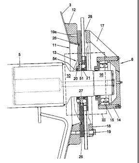
Fig. 2 shows the portion XT of Fig. 1 on a larger scale. The central
shaft 5 passes from the interior of the tank by way of a reduced journal 10
through a wide opening 11 in the end shield 3 of the tank 2, and through a
sealing construction J.3, mounted on the end shield 3 via a supporting ring
1~, to outside the tank. Furthermore, beyond the sealing construction 1.3, an
external bearing constxuction 8 is mounted, remote from the sealing
construction, an the suppaxting ring 12. The bearing construction $
comprises a hearing house 14 which, in this example, includes a ball bearing
1~ which, in this example, receives the slightly further reduced end paxt lfi
of the journal 10. The bearing house 14 is connected through a number of
radially distributed arms 1'7, one of which is visible, to a mounting ring 18,
which in turn is attached to the supporting ring 12 with bolts 19.
It is noted that Figs. 2 and 3 show the sealing constxuction at the non-
driven end of the central shaft. However, a sealing construction according to
the invention can also be used at the other end of the shaft.
The example of a sealing construction according to the invention
shown in Frg. 2 is shown schematically on a slightllr larger scale in Fig. 3.
In
Figs. 2 and $ it can be seen that the sealing construction in the example
shown comprises, viewed in axial direction aid with respect to the interior
CA 02514008 2005-07-28
rJ
of the tan3~, an inner sealing ring 20 and a similarly shaped outer sealing
ring 21, both $tted on the journal 10.
The sealing rings are made of suitable elastic material and in this
example hare an annular body 22 of a substantially rectangular cxoss
section and having an axially outer surface 40, an axially inaer surface 41, a
radially outer surface 42 and a radialiy inner surface 4~. See also Fig. 4,
which schematically shows a cross section of an example of a sealing ring
according to the invBntion on a still slightly larger scale. The annular body
22 forms directly a sealing with respect to the journal 10. ~rthermore, the
IO annular body is provided with a sealing lip 23, which extends obliquely
upwards and in mounted condition aut~rards from the annular body, more
specifically, from a both radially and axially outer edge of the annular body.
In the example shown, the sealing lip 23 extends in line with a diagonal of
the annular body, that is, from the transition area between the surfaces 40
and 42 in p'ig. 4. The sealing lips 23 of sealing rings 20, 21 form a sealing
edge 24, which operatively forms a sealing relative to a radial surface of the
sealing construction.
li~xamples of suitable materials for the sealing rings are rubber ar
rubbery materials, such as for instance food-approved FPM polyraers, or
FPDM and like materials.
The asalin.g construction furthermore comprises a disc-shaped house
2b, which is provided with positioning means to fix the sealing rings. The
disc-shaped house is mounted on the supporting ring 12 with bolts 19a or
the like, with interposition of sealing mesas such as an 0-ring 2fi.
In this example, the disc-shaped house 25 is provided with a central
disc-shaped recess, in which a ring 27 is mounted. The ring 2'7 abuts by its
surface facing the interior of the tank, with interposition of a first O-ring
28a, against a radial flange 29 of the disc-shaped house 2b. The ring 27
further abuts by its axially outwardly facing surface, with interposition of a
second O-ring 2$b, against an annular member ~0, which forms a central
CA 02514008 2005-07-28
chamber 31 axound the journal 7Ø The central chamber 31. is connected via
at least one bare 32 in the annular membax 34 with at least one supply lixre
33 for cleaning liquid. The central chamber 31 is furthermore connected via
at least one other bore 34 with at least one drain line 35 for leakage fluid
and cleaning liquid. It is also possible, however, to use one or more
eornbiued supP)~'~dxain lines.
In the chamber 31, furthermore, the outer sealing ring 21 is situated.
The lip 23 of the outer sealing ring 21, extending obliquely outwards from
the radially and a~cially outer edge of the annular body, has its sealing edge
14 24 abutting against a radial inner surface 37 of an outer wall 36 of the
chamber 31.
~xrthermore, adjacent the journal 10, the outer ~au~all 36 of the
chamber 31 is provided with cams 38 extending axially in~avards under the
sealing lip 23 of the outer sealing ring 21, which cams 38 abut against the
axially outer surface 44 of the annular body 22 of the sealing ring 21,
Ix~tead of the cams 38, also an annular shoulder with cross grooves or the
like could he used.
The outer sealing ring 2I furthermore abuts by its axially inner
surface 4I against the axially outer surface 50 of the ring 27. mhe ring 2'~,
fuxther, is provided, in its axially outer surface 5(~ adjacent the sealing
ring
21, with radially distributed recesses 51, which farm a passage for cleaning
liquid. The ring 27, similarly to the chamber wall 36, is provided, on the
axially inner surface 52, that is, the surface facing the interior of the
tank,
with cams 53 or the lime which, under the sealing lip 23 of the inner sealing
ring, abut against the axially outer surface 40 of the inner sealing ring 20.
The sealing lip 23 of the inner sealing ring 20 then abuts by its sealing edge
24 against the surface 62 of the ring 27.
The axially innex surface 41 of the inner sealing ring 20 abuts against
radially distributed fingers 54 of the disc-shaped house 25.
CA 02514008 2005-07-28
7
As a xesult of the construction described, the annular bodies of the
sealing rings 20 and 21 are directly fixed relative to the end shield 3 of the
tank. Tf the journal 14 and thB tank wall move relative to each other in axial
direction, the sealing rings reraain in the same position relative to the tank
wall, and the radially inner surfaces 43 of the sealing rings slide over the
journal without the sealing lips 23 thereby being loaded or chapging their
orientation. The sealing action of the sealing lips 23 is therefore not
influenced.
The angers 54, the ring 27 and the annular member 30 surround the
jouxnal 10 with some clearance "d", thereby allowing a slight radial
movement of the journal 10 relative to the sealing construction. Upon such a
movement, the sealing edges 24 of the sealing lips slide to same extent over
the radial surfaces 3'7 and 52 of the chaxaber wall 36 and the ring 2?, while
the original orientation of the sealing lips is substantially preserved and
the
sealing action remains guaranteed.
If in the chamber 31 andlar in the interior of the tank an increased
liquid pressure occurs, the sealing lips 23 of the sealing rings are pushed
more firmly against the surfaces 37 and 52, respectively, so that the sealing
action can increase further.
24 During a cleaning cycle, with the drain line 35 closed, cleaning liquid
is supplied under pressure via the supply line 33 for cleaning liquid and the
bare 32 to the chamber 31. This cleaning liquid cannot pass the lip 23 of the
outer sealing ring 21, but via the recesses 51 in the ring 27 and via the
space between the ring 2? and the journal 10 and via the ixitermediate space
2~ between the caans 53, can reach the space 55 under the sealing lip 23 of
the
inner sealing ring. mhe lip 23 can bend upwards under the influence of the
pressure exerted by the cleaning liquid, allowing the cleaning liquid to pass,
whereby the apace under the lip is cleaned.
It is noted that after the foregoing, various constructional
30 modifications will readily occur to those skilled in the art. Thus, if
desixed,
CA 02514008 2005-07-28
the sealing construction described can be designed with a sealing ring
according to the invention in one receiving apace and a dift'erent type of
sealing ring in the other receiving space. Also, if desired, the sealing
construction can be designed with just a single receiving space for a sealing
ring. In that ease, in the example shown, for instance the outer receiving
space situated betwee~l the ring 27 and the chamber wall 36, and the sealing
ring 21 could be omitted. The ring 27 could then be attached by means of
bolts or the like to the disc-shaped house 25. The sealing would then be
provided by the sealing rang 20 situated in the receiving space formed
between the axially inner surface of the ring 27 and the finger$ 54. Such a
singular seal could for instance be used in a curd tank for making flat
cheese, or in a curd distxibution tank for block formers or in a mixing tani~
far curd and cream, Furthermore, if desired, it would be possible to design
the sealing construction with more than two axially consecutive receiving
spaces for sealing zings, with a sealing ring according to the invention being
used in at least one receiving space.
Also, for retaining the inner sealing ring or a single sealing ring on
the side facing the interior of the tank, instead of the angers 54, a ring
arranged around the shaft or a shoulder of the shaft or a number of cams
provided on the shaft could be used.
These and similar modifications are understood to fall within the
framework of the invention.