Note: Descriptions are shown in the official language in which they were submitted.
CA 02514398 2005-07-26
WO 2004/066834 PCT/US2004/002172
PATIENT MONITORING DEVICE WITH MULTI-ANTENNA RECEIVER
The invention relates to implantable medical devices and, more particularly,
patient monitoring devices for communication with implantable medical devices.
Implantable medical devices typically include a wireless telemetry link that
permits
communication between the implanted medical device and an external programmer
or
patient monitoring device. The wireless telemetry link may permit the
transmission of
commands from a programmer or patient monitoring device to the implantable
medical
device, e.g., to program new features or functionality into the implantable
medical device.
Also, the wireless telemetry link may permit the programmer or monitoring
device to
interrogate the implantable medical device to obtain stored operational
information and
sensed physiological parameters.
A transceiver and antenna typically arc located within a housing associated
with
the implantable medical device. Conventional programmers and patient
monitoring
devices incorporate a transceiver head that is placed in close proximity to
the implantable
medical device for programming and interrogation. The transceiver head may be
coupled
to the programmer or monitoring device via a cord. More recently, telemetry
systems for
implantable medical devices have eliminated the need for a transceiver head in
the
programmer or monitoring device. Instead, various wireless communication
techniques
have been implemented to permit increased transmission distances between the
implantable medical device and the programmer or patient monitoring device.
Improved wireless communication techniques may permit the implantable medical
device to be located several meters from the programmer or monitoring device,
providing
the patient with increased mobility during programming and interrogation. In
some cases,
a patient monitoring device may be placed within the home of a patient, and
configured to
monitor the implantablc medical device by wireless telemetry during the course
of the
patient's daily routine. In addition, some patient monitors may take the form
of portable
devices that can be carried with the patient, e.g., much like a personal
digital assistant
(PDA) or cell phone.
In general, the invention is directed to a patient monitoring device having a
receiver capable of both single-antenna and multi-antenna operation. Multi-
antenna
operation permits the monitoring device to take advantage of spatial diversity
for
CA 02514398 2005-07-26
WO 2004/066834 PCT/US2004/002172
improved communication with an implantable medical device in the presence of
fading.
However, the small size of many patient monitoring devices can make the
incorporation of
multiple antennas difficult. To permit spatial diversity operation, the
invention provides a
base station having a second antenna that can be coupled to the patient
monitoring device.
Alternatively, the base station may have one or more high quality antennas
that are used
by patient monitoring device instead of the antenna in the patient monitoring
device when
the patient monitoring device is coupled to the base station.
The patient monitoring device may provide multi-antenna operation when it is
coupled to the base station, and single-antenna operation when it is not
coupled to the base
station. Alternatively, the patient monitoring device may use a high quality
antenna
provided in the base station when it is coupled to the base station. The base
station may
take the fornl of a docking station, platform, cradle or the like that
receives the patient
monitoring device and couples an antenna to the patient monitoring device,
c.g., for spatial
diversity or increased antenna quality. The patient monitoring device may
provide an
adaptable receiver and transmitter capable of operating in either the single-
antenna or
multi-antenna mode. In this manner, the invention can achieve spatial
diversity without
consuming additional space within the monitoring device for a second antenna.
In one embodiment, the invention provides a system comprising an implantable
medical device, a base station having a first antenna, and a monitoring device
having a
second antenna, wherein the monitoring device receives wireless signals from
the
implantable medical device via both the first antenna and the second antenna
when the
monitoring device is coupled to the base station.
In another embodiment, the invention provides a monitoring device for
monitoring
an implanted medical device, the device comprising a first antenna, a wireless
receiver
coupled t~ the first antenna to process signals received from the implanted
medical device
via the first antenna, and a terminal to couple the receiver to a second
antenna associated
with a base station to process signals received from the implanted medical
device via the
second antenna.
In a further embodiment, the invention provides a method comprising receiving
wireless signals from an implantable medical device via both a first antemia
associated
with a monitoring device and a second antenna associated with a base station
when the
CA 02514398 2005-07-26
WO 2004/066834 PCT/US2004/002172
monitoring device is coupled to the base station, and receiving the wireless
signals via
only the first antenna when the monitoring device is not coupled to the base
station.
In yet another embodiment, the invention provides a monitoring device for
monitoring an
implanted medical device, the monitoring device comprising a wireless receiver
to receive
signals transmitted by a transmitter, wherein the receiver receives the
signals via a first
antenna and a second antenna when the monitoring device is coupled to a second
device
and receives signals via only the first antenna when the monitoring device is
not coupled
to the second device.
In another embodiment, the invention provides a base station comprising an
antenna, and a terminal to connect the antenna to a monitoring device for
monitoring an
implantable medical device when the monitoring device is coupled to the base
station.
The invention includes various aspects. For example, the invention may permit
spatial
diversity operation in a patient monitoring device without the need to
incorporate an
additional antenna in the device. Instead, the patient monitoring device may
provide
single-antenna operation when it is not coupled to the base station and multi-
antenna
-. operation when it is coupled to the base station. Alternatively, the
patient moyitoring
device may use a high quality antenna provided in the base station instead of
the device
antenna.
When the patient monitoring device is not coupled to the base station, the
patient is
more likely to carry the monitoring device in closer proximity to the
implantable medical
device. In this case, single-antenna operation may be sufficient. When the
patient
monitoring device is not carried by the patient and, hence, may be further
away from the
implantable medical device, placing the patient monitoring device in the base
station
provides improved communication via spatial diversity techniques or via a
higher quality
antenna. In this manner, the invention may improve overall reliability of
communication
between the patient monitoring device and the implantable medical device.
The details of one or more embodiments of the invention are set forth in the
accompanying
drawings and the description below. Gther aspects of the invention will be
apparent from
the description and drawings, and from the claims.
FIG. 1 is a block diagram illustrating a system including a patient monitoring
device capable of mufti-antenna operation in accordance with the invention.
CA 02514398 2005-07-26
WO 2004/066834 PCT/US2004/002172
FIG. 2 is a block diagram illustrating a patient monitoring device and a base
station
in accordance with the invention.
FIG. 3 is a block diagram illustrating connection of a patient moutoring
device and
a base station in accordance with an embodiment of the invention.
FIG. 4 is a block diagram illustrating connection of a patient monitoring
device and
a base station in accordance with another embodiment of the invention.
FIG. 5 is a block diagram illustrating spatial diversity circuitry associated
with a
patient monitoring device.
FIG. 6 is a flow diagram illustrating a process for selection of single-
antenna or
mufti-antenna operation in a patient monitoring device.
FIG. 7 is a block diagram illustrating connection of a patient monitoring
device and
a base station in accordance with an added embodiment of the invention.
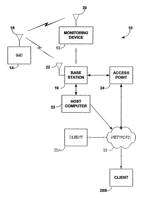
FIG. 1 is a block diagram illustrating a system 10 including a patient
monitoring device 12
capable of mufti-antenna operation in accordance with an embodiment of the
invention.
As shown in FIG. 1, system 10 may include monitoring device 12, an implantable
medical
device ("IMD") 14, and a base station 16. IMD 14 transmits signals via antemia
18 to
patient monitoring device 12. Monitoring device 12 includes an antenna 20.
Base station
16 includes an antenna 22. Monitoring device 12 may be used independently of
base
station 16 or coupled to the base station.
In accordance with the invention, monitoring device 12 is configured for
single-
antenna operation or mufti-antenna operation. In particular, monitoring device
12 uses
antenna 20 for communication with IMD 14 when the monitoring device is not
coupled to
base station 16. When monitoring device 12 is coupled to base station 16,
however, the
monitoring device uses not only antenna 20, but also antenna 22 provided in
base station
16. In this manner, monitoring device 12 can take advantage of spatial
diversity to
communicate with IMD 14 when the monitoring device is coupled to base station
16.
As further shown in FIG. 1 ~ base station 16 may be coupled to a host computer
23
that provides access to a network 26. Alternatively, base station 16 may be
coupled
directly to an access point 24 that provides to network 26. Network 26 may be
a local area
network, wide area network or global computer network, such as the World Wide
Web,
and provides communication between monitoring device 12 and one or more
network
clients 28. Monitoring device 12 or an application running on host computer 23
may
CA 02514398 2005-07-26
WO 2004/066834 PCT/US2004/002172
gather and forward data obtained from IMD 14 to the clients 28. Clients 28 may
be
associated with monitoring physicians and may run automated applications to
process
information received from monitoring device 12 via network 26.
Base station 16 may serve multiple purposes. In addition to providing a second
antemia for spatial diversity, base station 16 may operate as a docking
station to permit
wired or wireless communication of monitoring device 12 with host computer 23
or
network access point 24. In some embodiments, base station 16 may facilitate
synchronization of data stored within monitoring device 12 with data stored by
host
computer 23 or one or more of clients 28. In this sense, base station 16 may
operate much
like a "synch" cradle used with many conventional PDAs. Also, base station 16
may serve
to charge a rechargeable battery within monitoring device 12 when the
monitoring device
is coupled to, e.g., docked within, the base station.
Monitoring device 12 may be used with a variety of different IMDs 14 including
a
cardiac stimulator, a neuro stimulator, a drug delivery device, and a
physiological sensor
device. One example of an implantable medical device 14 is a pacemaker.
Another
example of an implantable medical device is a pacemaker-cardioverter-
defibrillator
("PCD"). Other examples include an implantable brain stimulator, an
implantable gastric
system stimulator, an implantable nerve stimulator or muscle stimulator, an
implantable
lower colon, an implantable drug or beneficial agent dispenser or pump, an
implantable
cardiac signal loop or other type of recorder or monitor, an implantable gene
therapy
delivery device, an implantable incontinence prevention or monitoring device,
an
implantable insulin pump or monitoring device, and so on. IMD 14 may
continuously
collect operational information and physiological information. The
physiological
information may include heart rate, heart rate variability, blood glucose
levels, oxygen
saturation, partial pressure of oxygen in the blood, blood pressure, baro-
reflex measures,
electrogram morphologies, lung wetness, and the like.
Antenna 20 of monitoring device 12 is coupled to a wireless receiver to
process
signals received from IMD 14. In addition, antenna 20 may be coupled to a
wireless
transmitter. Accordingly, monitoring device 12 may be designed for one-way or
two-way
communication with IMD 14. A transmitter may be used by monitoring device 12
to
program IMD 14. Also, in accordance with the invention, monitoring device 12
may
provide either single-antenna or multiple-antenna operation. In this manner,
monitoring
CA 02514398 2005-07-26
WO 2004/066834 PCT/US2004/002172
device 12 may be configured to provide a spatial diversity mode in which the
receiver
processes signals received via both antenna 20 and antenna 22.
Monitoring device 12 may take a variety of forms. For example, monitoring
device 12 may be a dedicated monitoring device. Alternatively, monitoring
device 12 may
be integrated with other device functionality. In particular, monitoring
device 12 may be
integrated with a cell phone, a PDA, or the like. The monitoring device 12 may
receive
wireless signals from IMD 14 via only antenna 20 when it is not coupled to
base station
16. Additionally, the monitoring device 12 may receive signals from IMD 14 via
both
antenna 20 and antenna 22 when it is coupled to base station 16.
FIG. 2 is a block diagram illustrating a patient monitoring device 12 and a
base
station 16 in accordance with one embodiment of the invention. As shown in FIG
2, base
station 16 may define a cradle, platform or other support to receive
monitoring device 12
and provide engagement between contact terminals associated with the base
station and
the monitoring device. In particular, monitoring device 12 may include a
contact terminal
to couple the receiver to a second antenna 22 provided in base station 16.
Base station 16
may include a reciprocal terminal that engages the contact terminal in
monitoring device
12 to couple antenna 22 to the monitoring device. Alteniatively, in other
embodiments,
antenna 22 of base station 16 may be coupled to monitoring device 12 via a
cable.
In the example of FIG. 2, monitoring device 12 includes antenna 20, a display
screen 32 and user input media such as an array of buttons 34. Base station 16
includes
antenna 22, and a cradle-like receptacle to receive monitoring device 12 and
facilitate
engagement of reciprocal contact terminals in the monitoring device and the
base station.
Base station 16 may be coupled to a source of power via a power cord (not
shown in FIG.
2). In addition, base station 16 may include communication links to host
computer 23 or
access point 24. FIG. 2 depicts antenna 22 is shown as protruding from base
station 16.
In other embodiments, however, antenna 22 could be a dedicated, free-standing
antenna
that is coupled to base station 16 via a cable. Alternatively, antenna 22
could be integrated
with a power cord associated with base station 16, or embedded within the
housing of the
base station.
In some embodiments, base station 16 may further include radio circuitry to
process wireless signals received via antenna 22. In other words, base station
12 may
provide some of the circuitry necessary to process one of the spatial
diversity channels
CA 02514398 2005-07-26
WO 2004/066834 PCT/US2004/002172
involved in transmitting or receiving signals via multiple antennas 20, 22. In
this manner,
base station 16 may further reduce the size, power consumption and complexity
of
monitoring device 12. Alternatively, such circuitry may be provided in
monitoring device
12, with base station 16 providing a simple electrical pass-through from
antenna 22 and
the monitoring device.
In accordance with the invention, a monitoring device 12 that is capable of
single-
antenna or mufti-antenna communication can provide more reliable communication
between IMD 14 and the monitoring device. Monitoring device 12 can take
advantage of
spatial diversity without the need to incorporate an additional antenna in the
monitoring
device. Instead, monitoring device 12 cooperates with its own base station 16
to provide
spatial diversity, thereby reducing the size, cost and complexity of the
monitoring device.
The space required for the second antenna 22, and perhaps radio circuitry for
processing
signals received and transmitted by the second antenna, can be provided by
base station
16.
FIG. 3 is a block diagram illustrating connection of patient monitoring device
12
and base station 16 in accordance with an embodiment of the invention. As
shown in FIG
3, monitoring device 12 includes transmitter/receiver (TX/R~i) circuitry 36 to
process
signals received and transmitted by antenna 20 in monitoring device 12 and
antenna 22 in
base station 16. In particular, TX/RX 36 may be coupled to antenna 20 and a
terminal 38.
In addition, T~/RX 36 may be coupled to a modem 41 that modulates and
demodulates
signals transmitted and received via antenna 20 or both antennas 20, 22.
When monitoring device 12 rests in or on base station 16, terminal 38 contacts
a
terminal 40 in base station 16. Terminal 40 may be coupled to antenna 22 or,
alternatively,
radio circuitry with base stati~n 16 that processes signals transmitted and
received by
antenna 22. Additi~nal terminals 42, 44 may be provided on monitoring device
12 and
base station 1 G, respectively, for exchange of data and battery charging
current.
Monitoz~ing device 12 processes signals exchanged with II~1~ 14=. T~/I~ 4~6 in
monitoring device 12 may include a spatial diversity receiver and transmitter
to process
signals received and transmitted via antenna 20, 22. In ~ther embodiments,
monit~ring
device 12 may not include a transmitter and instead serves only to gather data
from I1VID
14. When monitoring device 12 is not coupled to base station 12, it receives
signals via
antenna 20. When moiutoring device 12 is coupled to base station 12, however,
it receives
CA 02514398 2005-07-26
WO 2004/066834 PCT/US2004/002172
signals via both antennas 20, 22. Accordingly, TX/RX 44 may provide an auto-
detection
feature that automatically detects the connection of antenna 22 via contact
terminals 38,
40.
FIG 4 is a block diagram illustrating connection of patient monitoring device
12
and base station 16 in accordance with another embodiment of the invention.
FIG 4
conforms substantially to FIG 3 but illustrates incorporation of TX/RX
circuitry within
base station 16 to process signals for antenna 22. In particular, first TX/RX
circuitry 36A
is provided in monitoring device 12 to process signals for antemia 20, and
second TX/RX
circuitry 36B is provided in base station 16 to process signals for antenna
22. TX/RX
circuitry 36A, 36B may perform filtering, amplification, upconversion or
dov~nnconversion
of signals transmitted or received by antennas 20, 22, respectively.
Accordingly, each of
TX/I~X circuitry 36A, 36B may be coupled to modem 41. However, TX/RX circuitry
36B
is coupled to modem 41 via terminals 38, 40 upon coupling of monitoring device
12 with
base station 16.
FIG. S is a block diagram illustrating spatial diversity circuitry associated
with a
patient monitoring device l2. As shown in FIG 5, _monitoring device may
include _
separate channels for processing signals transmitted or received by antennas
20, 22 to
spatial diversity. Qne channel includes radio frequency (RF) circuitry 46A and
analog-to-
digital (ADC)/digital-to-analog (DAC) circuitry 48A to process signals for
antenna 20. A
second chamiel includes RF circuitry 46B and ADC/DAC circuitry 48B to process
signals
for antenna 22. RF circuitry 46A, 46B may include conventional filtering,
amplification,
downconversion, and upconversion circuitry to process signals transmitted and
received
by antennas 20, 22, respectively. Also, ADC/DAC circuitry 48A, 48B converts
digital
signals generated by modem 41 into analog signals for transmission on antennas
20, 22,
and converts analog signals received by antennas 20, 22 to digital signals for
demodulation by modem 41.
FIG. 6 is a flow diagram illustrating a process for selection of single-
antenna or
multi-antenna operation in a patient monitoring device. As shown in FIG. 6, if
monitoring
device 12 is in an operating mode that supports receive/transmit (12X/TX)
diversity (50).
If RX/TX diversity is not supported, monitoring device 12 processes signals
received and
transmitted by a single antenna (58). If RX/TX diversity is supported,
however,
monitoring device 12 determines whether it is coupled to base station 16 (60).
Monitoring
CA 02514398 2005-07-26
WO 2004/066834 PCT/US2004/002172
device 12 may detect whether it is coupled to base station 16 by sensing
signals on one or
more contact terminals that engage contact terminals on the base station. If
monitoring
device 12 is coupled to base station 16, the monitoring device processes
signals received
and transmitted by multiple antennas (62). In other words, monitoring device
12 provides
spatial diversity when it is coupled to base station 16. In this case,
monitoring device may
offer enhanced communication with IMD 14.
FIG. 7 is a block diagram illustrating connection of a patient monitoring
device and
a base station in accordance with an added embodiment of the invention. The
example of
FIG 7 conforms substantially to that of FIG 3. Instead of providing spatial
diversity
operation, however, patient monitoring device 12 includes a switch 58 that
permits
operation using either antenna 20 associated with the patient monitoring
device, or antenna
22 associated with base station 16. Antenna 22 of base station 16 may be a
higher quality
antenna relative to antenna 20 of patient monitoring device 12. For example,
antenna 22
may have larger or more favorable dimensions, or be made of more favorable
materials,
than antenna 20 due to size, space, complexity or cost limitations associated
with patient
monitoring device 12.
Switch 58 may be configured to select one of antennas 20, 22 for used by RX/TX
circuitry 36. If patient monitoring device 12 is not coupled to base station
16, switch 58
selects antemia 20. ~n the other hand, if patient monitoring device 12 is
coupled to base
station 16, switch 58 selects the higher quality antenna 22 for enhanced
communication
with IMI? 14. In other words, in the exemplary embodiment of FIG 7, patient
monitoring
device 12 may be configured to use antenna 22 instead of antenna 20 when
antenna 22 is
available for use. As a further alternative, antemia 22 may incorporate two
more antennas
for spatial diversity operation. In this case, switch 58 may couple multiple
antennas from
base station 16 to I~/T~ circuitry 36, enabling spatial diversity
communication by patient
monitoring device 12 when it is coupled to base station 16.
5~arious embodiments of the invention have been described. These and other
embodiments are within the scope of the following claims.