Note: Descriptions are shown in the official language in which they were submitted.
CA 02515044 2005-08-03
WO 2004/072436 PCT/US2004/002815
APPLICATION FOR PATENT
Inventors: Michael A. Carmody; Matthew J. Jabs; Harold E. Payne;
and Mark K. Adam
Title: Shoe for Expandable Liner System
FIELD OF THE INVENTION
[0001] The field of this invention is the method of running a tubular inside
casing and securing it and more particularly to techniques for protecting the
mounting
location for the tubular on the casing as the casing is cemented.
BACKGROUND OF THE INVENTION
[0002] Figure 1 is illustrative of the prior techniques of running in casing
with
a casing shoe 16 near its lower end. If later a tubular is run in and needs to
be attached
to the casing by expansion, the presence of cement debris in the support area
on the
casing where the tubular will be attached could prevent a sealed connection
from
being obtained. One way around that would be to deliver the cement into a shoe
mounted below the point at which the liner will be attached later. Another
method
would be to run brushes and scrapers into the mounting location after
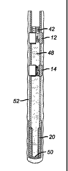
cementing to be
sure it was clean so that a good seal and support for the tubular subsequently
installed
can be obtained. However these techniques require significant amounts of time
and
create an associated cost.
[0003] The present invention protects the mounting location on the casing
during cementing with a sleeve that covers a recess. The sleeve defines a
sealed
annular space that contains an incompressible material. This allows the sleeve
to be
compliant to changes in hydrostatic pressure as the casing is lowered into
place.
Cementing is done through the sleeve. The sleeve is subsequently drilled out
exposing
a recess and a locating groove. The tubular can then be positioned accurately
and
expanded in to sealing contact with the casing. Due to the recess, the drift
diameter of
the tubular after expansion into the recess is at least as large as the casing
drift
diameter. The entire tubular can be expanded to its lower end and a run in
shoe at the
lower end of the tubular can be retrieved and removed from the well with the
swaging
assembly and the running string that delivered it. These advantages and others
of the
CA 02515044 2005-08-03
WO 2004/072436 PCT/US2004/002815
present invention will be readily appreciated by those skilled in the art from
a review
of the description of the preferred embodiment and the claims that appear
below.
SUMMARY OF THE INVENTION
[0004] An apparatus to protect the mounting area of casing when subsequently
attaching a tubular is disclosed. A sleeve that defines a sealed cavity having
a loose
incompressible material inside covers the mounting location on the casing. The
cementing of the casing takes place through the sleeve. After the cementing,
the
sleeve is drilled out and the incompressible material is removed to the
surface with the
drill cuttings. A tubular is inserted in the casing and is preferably expanded
into
sealing contact with the mounting location on the casing. At the end of
expansion, the
run in shoe on the tubular is retrieved.
DETAILED DESCRIPTION OF THE DRAWINGS
[0005] Figure 1 is a prior art production casing illustrating a standard
casing
shoe at the lower end;
[0006] Figure 2 shows a production string with the shoe track of the present
invention;
[0007] Figure 3 shows the production casing with the shoe track of the present
invention run into the wellbore;
[0008] Figure 4 is the view of Figure 3, after cementing;
[0009] Figure 5 is the view of Figure 4 showing the shoe track exposed after
drillout and the wellbore extended below the production casing;
[0010] Figure 6 is the view of Figure 5 showing the reaming of the extension
bore just drilled;
[0011] Figure 7 is a close up view of the now exposed shoe;
[0012] Figure 8 shows the liner run in on a running tool and in position to be
expanded;
2
CA 02515044 2005-08-03
WO 2004/072436 PCT/US2004/002815
[0013] Figure 9 is the view of Figure 8 indicating the initial stroking of the
swage, which results in release from the running tool;
[0014] Figure 10 is the view of Figure 9 showing the anchor released and
weight being set down to reposition for the next stroke of the swage;
[0015] Figure 11 is the view of Figure 10 showing the next stroke of the
swage;
[0016] Figure 12 is the view of Figure 11 showing the swage advancing
toward the lower end of the liner;
[0017] Figure 13 is the view of Figure 12 with the swage now engaging the
running shoe of the liner at its lower end;
[0018] Figure 14 is the view of Figure 13 with the liner fully expanded and
the
swage being removed with the running shoe by withdrawing the running tool from
the
fully expanded liner;
[0019] Figure 15 is a close up view of the sleeve protecting the recessed shoe
during cementing;
[0020] Figures 16a-16b show the capture of the guide nose assembly;
[0021] Figures 17a-17b show the shearing out of the guide nose assembly
from the tubular or liner;
[0022] Figures 18a-18b show the guide nose fully released and captured; and
[0023] Figures 19a-19b show the emergency release feature.
DETAILED DESCRIPTION OF THE PREFERRED EMBODIMENT
[0024] Figure 1 illustrates a production casing 10 having a lcnown landing
collar 12 and a standard float collar 14 as well as a casing shoe 16 adjacent
its lower
end 18.Typically, in the past, the cement is pumped through the casing shoe 16
and
then a dart or wiper is used to displace cement from the casing 10 and out
through the
shoe 16 and into the surrounding annulus. When the well is to be drilled
deeper, the
shoe 16 is drilled out but residual cement could still be present. The
presence of such
3
CA 02515044 2005-08-03
WO 2004/072436 PCT/US2004/002815
cement or shoe debris after drilling can affect the seal that is subsequently
needed
when a liner is inserted and secured to the casing 10. This is particularly a
concern
when the liner is to be expanded to secure it to the casing 10.
[0025] The present invention addresses this concern with a sleeve 20 shown in
Figures 2 and 15. As shown in Figure 15, the production casing 22 has a lower
section
24. Inside section 24 is a sleeve 20 mounted preferably concentrically and
defining an
annular space 28 that contains an incompressible material 30. Preferably the
incompressible material 30 is loosely mounted sand but other materials can be
used.
The purpose of the material 30 is to allow flexing in response to increasing
hydrostatic pressures as the depth of the casing 22 increases, when it is
lowered into
initial position. Sleeve 20 is preferably fiberglass sealed at ends 32 and 34.
Sleeve 20
initially covers locating recess 36 and long recess 38, which will later serve
as the
location for securing a tubular such as a liner by a variety of methods. The
preferred
method of expansion will be described in more detail below. Sleeve 20 is
preferably a
non-metallic or some other material that can be quiclcly drilled such as
plastics or
composites, to mention a few. During cementing of the casing 22, the sleeve 20
has an
inner surface 40, which is contacted by the cement. Ultimately a dart or wiper
plug 42
passes through casing 22 and lands on landing collar 12 (see Figure 4) to
displace
most of the cement out of the casing 22 and into the surrounding annulus. The
sleeve
20 is subsequently drilled out allowing the incompressible material 30 to
escape and
exposing the clean locating recess 36 and the long recess 38 for subsequent
attachment of a tubular as will be described below. The drilling removes a
part of seal
rings 42 and 46 without damaging the casing 22 or lower section 24.
[0026] The method can be understood by beginning at Figure 3, where the
casing 22 is mounted in the desired position for cementing in the wellbore 26.
The
assembly includes landing collar 12 and float collar 14. The assembly shown in
Figure 15 is at the lower end of the assembly, but for clarity only the sleeve
20 is
referenced in the schematic illustration.
[0027] Figure 4 shows that cement 48 has been displaced by plug 42 landing
on landing collar 12. As a result, cement 48 is pushed through sleeve 20,
through run
in shoe 50 and into annulus 52.
4
CA 02515044 2008-01-25 [0028] In Figure 5, a drill sWng 54 with a bit assembly
56 has been advanced
through the casing 22 and has milled out the wiper 42 and the sleeve 20 to
expose
locating recess 36 and long recess 38. The incompressible materia130 is
released and
circulated to the surface with the drill cuttings from the action of bit
assembly 56.
[0029] Figure 6 illustrates the enlarging of the new section of wellbore 58 to
a
new dimension 60 using an under-reamer or an RWD bit 62. Depending on the
nature
of the bit assembly 56, the wellbore 60 can be created in a single trip in the
hole or in
multiple trips. Figure 7 shows the drilling of wellbore 60 complete and the
string 54
and bit assembly 56 removed from the wellbore 60 and stored at the surface.
[0030] Figure 8 shows a running string 64 that supports a liner or other
tubular
66 at locking dogs 68. The assembly further comprises an anchor 70 with slips
72 that
are preferably pressure sensitive to extend slips 72 and allow them to retract
when
pressure is removed. Also in the assembly is a piston and cylinder combination
74
that drives a swage 76, in response to pressure applied to the piston and
cylinder
combination 74. Initially, as illustrated in Figure 9, pressure is applied to
extend the
slips 72 and drive down the swage 76 as illustrated schematically by arrows
78. The
upper end 80 of the tubular 66 is expanded into long recess 38 for support
from casing
22. As swage 76 stroked enough to suspend the tubular 66 to casing 22 the dogs
68
become undermined and release their grip on tubular 66. As shown in Figure 10,
the
dogs 68 have released and the slips 72 have been released. When weight is set
down
at the surface, after internal pressure is removed, the piston and cylinder
combination
74 is re-cocked for another stroke for swage 76. Figure 11 shows the
subsequent
stroking, fiuther expanding the tubular 66. Optionally, one or more open hole
packers
82 can be used to ultimately make sealing contact in wellbore 60 after
expansion.
10031] Figure 12 illustrates the continuation of the movement of the swage in
response to applied surface pressure to anchor 70 and piston and cylinder
combination
72. Those skilled in the art wilt appreciate that force magnification can be
incorporatad into piston and cylinder combination 72 and a greater force can
be
applied to swage 76 at the beginning of each stroke as compared to the balance
of
each stroke. However, other techniques can be used
CA 02515044 2005-08-03
WO 2004/072436 PCT/US2004/002815
for swaging or even to secure the tubular 66 to long recess 38 or another
location
initially covered by a sleeve such as 20 during cementing of the casing 22,
without
departing from the invention.
[0032] Eventually, the running string 64 expands the open hole packers 82
into sealing contact with the wellbore 60 as it approaches the run in shoe 84
mounted
near the lower end 86 of tubular 66. A grasping mechanism 88 is shown
schematically
at the lower end of running string 64. Contact is made and the run in shoe 84
is
grabbed by mechanism 88. Swage 76 expands lower end 86 of tubular 66 enough so
that the run in shoe is released. When the string 64 is removed from the
wellbore 60
and to the surface, it takes with it the anchor 70, the piston and cylinder
combination
74 and the run in shoe 84, leaving a large opening 90 in the lower end of
tubular 66,
as shown in Figure 14. Those skilled in the art will appreciate that the run
in shoe 84
facilitates insertion of the tubular 66 by presenting a blunt nose as the
tubular is
initially advanced into position, as shown in Figure 8. It has a valve in it
to allow
circulation to facilitate insertion of the tubular 66. Removal of the run in
shoe 84 as
described above presents a large opening in the lower end of the tubular 66 to
facilitate subsequent drilling operations or other completion techniques.
[0033] Figures 16-19 show the grasping mechanism 88 in greater detail. It has
a top sub 100 connected at thread 102 below dogs 68. Top sub 100 is connected
to
mandrel 104 at thread 106. The run in shoe 84 is attached to tubular 66 by
virtue of
split ring 108 held against rotation by pin 110, which extends from shoe 84.
Threads
112 on ring 108 mesh with threads 114 on tubular 66. Ring 116 holds ring 112
in
position on shoe 84. Shoe 84 has a groove 118 and a stop surface 120. Top sub
100
has a surface 122 that lands on surface 120 as the grasping mechanism 88
advances
with the swage 76. When surface 122 hits surface 120 the tubular 66 has not
yet been
expanded. Mandrel 104 has a series of gripping collets 124 that land in groove
118
when surfaces 120 and 122 connect. When this happens, as shown in Figure 16a
the
collets are aligned with recess 126 on mandrel 104 so that they can enter
recess 118 in
shoe 84. Mandrel 104 has a ring 128 held on by shear pins 130. When a downward
force is applied to shoe 84 through the contact between surfaces 120 and 122,
tlireads
112 and 114, shear out and the shoe 84 drops down and is captured on ring 128.
At
this point, shown in Figure 17a, surface 132 on mandrel 104 supports collets
124 in
6
CA 02515044 2005-08-03
WO 2004/072436 PCT/US2004/002815
groove 118. The shoe 84 is now captured to the mandrel 104. As the mandrel 104
moves down in tandem with the swage 76, the tubular 66 is expanded to bottom.
Thereafter, the swage 76 and the grasping mechanism 88 and the attached shoe
84 can
all be removed to the surface, as shown in Figure 18a. If, for any reason the
shoe 84
fails to release from the tubular 66 or gets stuck on the way out to the
surface, a pull
on the string 64 shears out pins 130, allowing the collets 124 to become
unsupported
as surface 134 is presented opposite recess 118 as shown in Figure 19a. Those
skilled
in the art will appreciate that other devices can be used to snare the shoe 84
as the
swage 76 advances. The ability to remove shoe 84 is advantageous as it removes
the
need to mill it out and further reduces the risk of the shoe 84 simply turning
in
response to a milling effort, once it is no longer held against rotation by
the now
expanded tubular 66.
[0034] Those skilled in the art will now appreciate the advantages of the
present invention. The sleeve 20 shields subsequent mounting locations for the
tubular
66 on casing 22 from contamination with the cement 48 used to seal the casing
22.
Thus regardless of the method of sealed attachment between the tubular 66 and
the
casing 22, there is a greater assurance that the proper sealing support will
be obtained
without concern that cement may have fouled the mounting location. The
assembly
including the sleeve 20 is compliant to changes in hydrostatic pressure
resulting from
advancement of the casing 22 downhole. At the conclusion of expansion or other
technique to secure tubular 66 to casing 22, the lower end of the tubular 66
is left
open as the run in shoe 84 is retrieved.
[0035] The foregoing disclosure and description of the invention are
illustrative and explanatory thereof, and various changes in the size, shape
and
materials, as well as in the details of the illustrated construction, may be
made without
departing from the spirit of the invention.
7