Note: Descriptions are shown in the official language in which they were submitted.
CA 02515678 2005-08-10
WO 2004/071757 PCT/US2004/003859
CUTTING SUBSTRATE AND METHOD OF MANUFACTURING SAME
Technical Field
[001] The present invention relates generally to protective media, and more
particularly
to a processing substrate and/or support surface.
Background Art
[002] Management of bacteria, liquids, fats and other waste during the
preparation and
handling of foods is of concern in food handling areas. Typically, such areas
include the
kitchen, although modern lifestyles include out-of home occasions such as
social and
recreational gatherings where food. is prepared, transported and/or served
outside of the
kitchen. Foods of particular concern from the standpoint of possibility of
food-borne
illness are fish, fowl and ground meats; although all foods present some
degree of risk.
Current media articles discuss the fact that the common cutting boards used in
the
preparation of foods are a source of food contamination. Other commonly used
food
preparation surfaces, such as countertops, also present some risk.
Specifically, it has been
found that bacteria can become entrapped in surface imperfections of the
cutting surface,
resulting in a surface that is difficult, if not impossible, to clean and/or
sterilize. The
cutting surface thus becomes capable of transferring bacteria to other foods,
which
provides a favorable media for pathogens to proliferate, resulting in an
increased potential
for food-borne illness, particularly when contact is had with high-risk foods.
In fact, some
foods considered to be pathogenically low-risk, such as fresh fruits and
vegetables can
become contaminated, waiting for the right environment for the bacteria to
proliferate.
[003] Another issue with cutting boards is the transfer of juices from the
cutting board to
other surfaces in the kitchen due to the fact that the cutting board is
normally not designed
to capture and contain juices during the cutting operation and thereafter
through final
disposal. In addition to the inconvenience of having to clean the countertop
or other
surfaces) exposed to the juices, a possibility exists that other food items
placed on such
surfaces) may be cross-contaminated.
[004] Products are in the marketplace today that attempt to address issues of
liquid, fat,
and bacteria management during cutting and general food preparation. However,
these
CA 02515678 2005-08-10
WO 2004/071757 PCT/US2004/003859
products fall short of optimum in one way or another. Specifically, they do
not absorb, are
not cut resistant, and/or fail to provide an effective bacteria barrier
between the food being
handled and the work surface. Also, bacteria are retained which can cause
contamination
during subsequent use.
[005] In addition to the foregoing, most, if not all, food preparation
surfaces lack one or
more of the following attributes:
1. a single use, disposable cutting surface that is virtually cut resistant
and
also entraps and holds waste and bacteria;
2. a food preparation surface which prevents food movement during
cutting;
3. a food preparation surface which prevents and/or selectively manages
movement thereof on the counter top during cutting;
4. a single-use food preparation surface which is easily disposed of while
securely containing contaminants; and
5. a single-use cutting surface that lays flat during use.
[006] Coggins U. S. Patent No. 5,520,945 discloses a disposable sheet that may
be used
in food service applications to prevent the cross-contamination of foods and
eliminate the
need for time-consuming clean-ups. The sheet comprises a porous layer that
allows
materials such as oil or flour to pass through, an absorbent layer that holds
the materials
passing through the porous layer, and a barrier layer that ensures that the
materials do not
contaminate a food preparation surface. The sheet has multiple uses such as
for rolling
dough, absorbing excess moisture, making sandwiches, cutting breads and
condiments,
and drawing excess oil away from fried items. The disposable sheet is only
disclosed for
use with items that do not require aggressive cutting, and hence, is not
adapted for use
with items that require substantial cutting pressures, such as meats and hard
vegetables.
[007] Thompson U. S. Patent No. Re. 36,717 discloses a flexible preparation
and transfer
sheet. The sheet comprises a homogeneous structure of polypropylene, with a
thickness in
a range between 0.010 to 0.030 inch. The sheet may be flexed about a
longitudinal
centerline whereupon the sheet material develops a cantilever beam strength
sufficient to
transport food articles after preparation to an appropriate container.
CA 02515678 2005-08-10
WO 2004/071757 PCT/US2004/003859
[008] Wu et al. U. S. Patent No. 6,021,524 discloses a polymeric film having
increased
cut resistance. The film comprises a polymeric matrix having a plurality of
cut resistance
fibers dispersed therein. The film is preferably made into medical or
industrial gloves.
[009] Otten et al. U. S. Patent No. 6,274,232 discloses an absorbent and cut-
resistant
sheet having a cut-resistant material with a plurality of openings, and an
absorbent
material attached to the cut-resistant material. A liquid impervious backing
layer is
preferably attached to the absorbent material to resist the escape of fluid
from the
absorbent material.
[010] PCT published application number WO 00/29209 discloses a flexible mat
for
absorbing liquids on floors or other surfaces. The mat includes a waterproof
backing layer
and a foam sheet formed by polymerization of a water-in-oil emulsion. The mat
can
optionally include a liquid pervious sheet and a non-skid material.
Summary of the Invention
[011] In accordance with one aspect of the present invention, a single use
processing
substrate includes a first section having a cut resistant surface, a second
liquid
impermeable section, and a fold line disposed along a length of the substrate
between the
first section and the second section, wherein folding along the fold line
forms the
processing substrate
[012] In accordance with another aspect of the present invention, a single use
processing
substrate comprises first means for providing a first section having a cut
resistant surface,
second means for providing a second liquid impermeable section, and third
means for
separating the substrate into the first and second sections and thereby
forming the
processing substrate.
[013] In accordance with yet another aspect of the present invention, a method
of
manufacturing a single use processing substrate includes the steps of
providing a first
section of a substrate having a cut resistant surface, providing a second
section of the
substrate having a liquid-impermeable surface, and creating a fold line
separating the first
section from the second section.
[014] Other aspects and advantages of the present invention will become
apparent upon
consideration of the following detailed description and the attached drawings,
in which
like elements are assigned like reference numerals.
CA 02515678 2005-08-10
WO 2004/071757 PCT/US2004/003859
4
Brief Description of the Drawings
[015] FIG. lA comprises an isometric view of a processing substrate according
to one
embodiment;
[016] FIG. 1B comprises an isometric view of a processing substrate according
to
another embodiment;
[017] FIG. 2 comprises a side elevational view of the processing substrate of
FIG. 1;
[018] FIG. 3 comprises a sectional view taken generally along the lines 3-3 of
FIG. 1;
[019] FIG. 4 comprises a perspective view of apparatus for producing
processing
substrates as shown in FIGS. lA;
[020] FIG. 5 comprises an isometric view of a processing substrate according
to another
I
embodiment;
[021] FIG. 6 comprises an isometric view of a processing substrate according
to another
embodiment;
[022] FIG. 7 comprises a cross sectional view of FIG. 6;
[023] FIG. 8 comprises an isometric view of a processing substrate according
to another
embodiment;
[024] FIG. 9 comprises an isometric rear view of a processing substrate
according to
FIG. 8;
[025] FIGS. 10-13 comprise plan views of processing substrates according to
other
embodiments;
[026] FIGS. 14 and 15 comprise isometric views of processing substrates in
roll form;
[027] FIGS. 16-19 comprise cross sectional views of processing substrates
according to
other embodiments;
[028] FIG. 20 comprises an elevational view of a processing substrate
according to
another embodiment;
[029] FIG. 21 comprises a cross sectional view of a processing substrate
according to
another embodiment;
[030] FIGS. 22 and 23 comprise isometric views of apparatus for producing
processing
substrates according to further embodiments;
[031] FIG. 24 comprises a cross sectional view of a processing substrate
according to
another embodiment;
CA 02515678 2005-08-10
WO 2004/071757 PCT/US2004/003859
[032] FIG. 25 comprises a plan view of the absorbent ply of the top layer of a
processing
substrate according to a further embodiment;
[033] FIG. 26 comprises a plan view of the absorbent ply of the top layer of a
processing
substrate according to another embodiment;
5 [034] FIG. 27 comprises an isometric view of an apparatus for producing a
processing
substrate as shown in FIG. 25;
[035] FIG. 28 comprises an isometric view of another apparatus for producing a
processing substrate as shown in FIG. 25;
[036] FIG. 29 comprises a plan view of a processing substrate according to a
further
embodiment;
[037] FIG. 30 comprises a sectional view of a first embodiment of the
processing
substrate of FIG. 30 along the lines 30-30;
[038] FIG. 31 comprises a sectional view of a second embodiment of the
processing
substrate of FIG. 30 along the lines 30-30;
[039] FIG. 32 comprises a plan view of a processing substrate according to
another
embodiment;
[040] FIG. 33 comprises a sectional view of the processing substrate of FIG:
32 along the
lines 33-33;
[041] FIG. 34 comprises a perspective view of an apparatus for producing the
processing
substrates of FIGS. 29-33;
[042] FIG. 35 comprises a plan view of the processing substrate according to
another
embodiment;
[043] FIG. 36 comprises an isometric view of the processing substrate of FIG.
25
partially folded;
[044] ~ FIG. 37 comprises a cross-sectional view of the processing substrate
of FIG. 25
completely folded in half;
[045] FIG. 38 comprises a cross-sectional view of another embodiment; and
[046] FIG. 39 comprises an isometric view of yet another embodiment.
Description of the Preferred Embodiments
[047] Referring now to FIG. lA, a processing substrate and/or support surface
that may
be used as a food preparation surface or sheet 10 preferably is planar (i.e.,
flat) in shape.
CA 02515678 2005-08-10
WO 2004/071757 PCT/US2004/003859
Alternatively, as seen in FIGS. 1B and 2, the sheet 10 may be tray-shaped and
includes a
substantially planar central portion or base 12 and inclined or curved side
surfaces 14a-
14d, wherein the base 12 and side surfaces 14 together define a generally
concave
structure. The side surfaces 14 may be formed by folding and/or scoring the
sheet 10 at
corner portions 15a-15d and optionally folding or scoring the sheet 10 at
portions 13a-13d
intermediate the base 12 and side surfaces 14. The inclined or curved side
surfaces 14
could alternatively be formed by any other process, such as forming through
the
application of heat, vacuum forming, vacuum pressure forming, or the like. If
desired,
fewer than four inclined side surfaces 14 may be provided. For example, only
the inclined
side surfaces 14a-14c may be employed to provide a flat edge surface that may
be oriented
toward the user so that an inclined side surface does not interfere with the
user's hands or
arms. Preferably, although not necessarily, the sheet 10 is intended for one
time use as a
cutting surface or as a sheet supporting an article or as a barrier for
isolating an article
resting on a surface (for example, a plant on a shelf, an article of food on a
counter or in a
microwave, or the like), or as a food preparation and bacteria management
sheet.
Following the use the sheet 10 and any waste products and contaminants carried
thereby
may be disposed of in any suitable fashion. The concave or tray-shaped
structure (if used)
facilitates retention of the waste products and contaminants during the food
preparation,
transport and/or disposal processes. Additionally or alternatively, the sheet
10 may be
sufficiently flexible to allow the user to bend andlor fold the sheet 10 to
prevent escape of
waste products and contaminants therefrom during disposal.
[048] Refernng also to FIG. 3, according to one embodiment, the sheet 10 also
includes a
cut-resistant, liquid-permeable top or upper portion or layer 16, which
substantially
prevents the integrity of the sheet 10 as a whole (and, in particular, the
layer 16) from
being compromised during cutting while at the same time allowing passage of
juices and
liquids through the layer 16. Preferably, the upper portion or layer 16 is
made of a
material sufficiently durable to withstand aggressive cutting of meats,
vegetables and other
food items by a serrated or non-serrated blade, particularly in the situation
where a cutting
motion is applied to meats, poultry or fish (or any other fibrous protein
material) that
results in the application of cutting force components in multiple directions
to the item. A
serrated blade presents a series of equally or non-equally spaced points or
tips to the upper
surface of the layer 16 that can snag or otherwise catch on edges of the
material used for
CA 02515678 2005-08-10
WO 2004/071757 PCT/US2004/003859
the top layer 16. Because of this it is generally preferred (although not
necessarily the
case) that the top layer 16 have irregularly or randomly spaced openings
therein that
prevent any points or tips from contacting material below the layer 16 during
cutting. In
this way, the possibility that the integrity of the sheet 10 would be
compromised is
reduced.
[049] In addition to the foregoing, the upper portion or layer 16 preferably
has an upper
surface 17 that is textured or otherwise formed to prevent slippage of items
thereon during
processing.
[050] The sheet 10 further includes a middle or intermediate portion or layer
18 that may
be made of a liquid absorbent material that retains the juices and liquids
passed by the
upper layer 16, as well as a bottom portion or layer 20, which is preferably
made of a slip-
resistant, liquid, and bacteria impervious material to prevent slipping of the
sheet 10 and
leakage of liquids and transfer of bacteria onto or from a work surface (such
as a
countertop, a cutting board, or the like) during use.
[051] The upper layer 16 may be of a length and width substantially equal to
the length
and width of the middle layer 18. Alternatively, the upper layer may be of a
smaller size
than the size of the layer 18, thereby providing a cutting surface that is
partially or fully
surrounded by portions of the middle layer 18. As a further alternative, the
top and bottom
layers 16, 20 may be of the same size and the middle layer may be of a smaller
size and so
arranged relative to the layers 16 and 20 such that the middle layer 18 is
surrounded by the
joined outer margins of the layers 16 and 20.
[052] If desired, the sheet 10 may instead include a different number of
layers or portions
each imparting one or more desired characteristics) to the sheet 10. In
addition, the sheet
10 may comprise a single layer or portion or multiple layers or portions
wherein each layer
or portion is made of material that is differentially treated during
production to obtain
multiple desired characteristics. Still further, the sheet 10 may include one
or more layers
or portions that are not differentially treated during production in
combination with one or
more layers that are differentially treated during production. For example,
the sheet 10
could comprise a single layer that is liquid absorbent, but which has a first
surface that is
treated (by any suitable process, such as the application of heat or a
chemical additive)
during production to produce a cut-resistant, liquid-permeable surface. The
sheet 10 may
further have a second surface opposite the first surface that may be treated
by any suitable
CA 02515678 2005-08-10
WO 2004/071757 PCT/US2004/003859
process (for example, as noted above) during production to produce a slip-
resistant barrier
surface. Alternatively, the sheet" 10 could comprise two layers, a first of
which provides a
slip-resistant barrier surface, and a second of which provides a cut-resistant
surface. In
this case, the liquid absorbent layer may be omitted, or the liquid-absorbent
material may
be provided as part of one of the first or second layers or as a separate
layer. Still further,
the slip-resistant surface and/or the cut-resistant, liquid-permeable surface
could be
omitted, if desired.
[053] The various layers 16, 18 and 20 are secured or formed together in any
suitable
fashion taking the various materials of the layers into account. For example,
two or more
of the layers 16, 18, and 20 may be heated to fuse the layers together or the
layers may be
laminated as part of an extrusion process. Two or more of the layers could
instead be
secured together by an adhesive including a hot melt adhesive as well as a
solvent or water
based adhesive, as long as the adhesive is approved for food contact and
compatible,with
the layers. Alternatively, two or more of the layers 16, 18, and 20 may be
formed using
materials and/or a manufacturing process which result in simultaneous
formation and
bonding of such layers. Still further, the layer 16 may be bonded or otherwise
secured to
the layer 20 at selected locations, thereby capturing the layer 18
therebetween. In this
case, the layer 18 may have one or more voids therein to facilitate the
joinder of the layers
16 and 20 at the locations) of the void(s). Still further, the layer 18 may be
omitted and
the layers 16 and 20 may be joined at spaced locations to create voids between
the layers
16, 20 which serve to attract and retain liquids) therein by capillary action.
[054] FIG. 4 illustrates an apparatus that may be used to produce a number of
cutting
surfaces as shown in FIG. lA. An extrusion die or other delivery device 40
deposits thin
streams of molten thermoplastic onto a web 42 of liquid-absorbent material,
such as
cellulosic tissue or batting. The material deposited on the web 42 is chosen
from but not
limited to polyolefins, such as polyethylene (PE), polyolefm metallocenes,
metallocene
polypropylene (mPP) or polypropylene (PP) including homopolymers and
copolymers
thereof, polyester, such as polyethylene terephthalate (PET), polystyrene
(PS), polyvinyl
alcohol (PVA), polyvinyl chloride (PVC), nylon (such as nylon 6 or nylon 66),
polyacrylonitrile (PAN), acrylonirile-butadiene-styrene (ABS), ethylene-vinyl
acetate
(EVA) copolymer, multi layers of the same or different polymers, blends and
recycled
polymers (including polymers that are cured by ultraviolet or visible light,
an electron
CA 02515678 2005-08-10
WO 2004/071757 PCT/US2004/003859
beam, water or other curing agent). Addition of one or more fillers) may be
advantageous
both from a cost advantage as well as improvement of modulus, heat distortion
and cut
resistance. Preferably, each stream is approximately on the order of 1-100
thousandths
inch (0.0254mm - 2.54mm) wide and are deposited at equally-spaced locations on
the web
42 approximately 1-500 (0.025mm-12.7mm) thousandths inch apart. Alternatively,
the
streams may be deposited at non- equally spaced locations on the web 42 and/or
may be of
differing widths and/or may be deposited at different points of time. Still
further, different
stream shapes (e.g., a wavy, curved, discontinuous or interrupted stream as
opposed to the
linear continuous stream extent described above and/or a different cross-
sectional shape)
and/or different materials could be sequentially deposited on the web 42. In
other words, a
single stream may comprise a first portion of a first material, a second
portion deposited
after the first portion of a second material, a third portion deposited after
the second
portion of a third material or the first material, etc. In an alternative
embodiment, adjacent
streams may be of differing materials. In a general sense, N different
materials may be
deposited or otherwise formed irz situ on the web 42 in a repeating or non-
repeating
sequence or pattern or in a random fashion. In the case of a repeating
sequence or pattern,
the repetition frequency may be established at a value less than or equal to
N. In any
event, the choice of materials, sequence or pattern, and the like affect the
physical
characteristics of the resulting surface.
[055] If the upper layer 16 is to be smaller than the size of the layer 18,
then the streams
are deposited only on a center portion of the web 42. In addition, the flow of
thermoplastic resin is periodically interrupted so that discrete portions of
web are formed
having thermoplastic thereon wherein such portions are separated by further
web portions
not having thermoplastic deposited thereon. The web 42 then passes between a
pair of
rolls 44a, 44b. Preferably, the roll 44a is smooth and the roll 44b has a
plurality of
diamond-shaped or other shaped protrusions 46 on the surface thereof. The
protrusions 46
deform and spread out the still molten thermoplastic streams to transform the
linear
streams into a desired two or three dimensional pattern of thermoplastic resin
on the web
42. The web 42 then passes between one or more additional pairs of rolls 48
that further
spread out and/or flatten the thermoplastic streams and impart a desired
texture thereto.
The resulting surface provides cut resistance and prevents food from sliding
thereon
CA 02515678 2005-08-10
WO 2004/071757 PCT/US2004/003859
[056] If desired, any pattern can be created on the web 42, for example, a
random pattern
or a crisscross pattern could be created by drizzling, spraying or otherwise
applying the
material thereto.
[057] Thereafter, the web 42 is inverted (i.e., turned over) and the layer 20
is formed ifz
5 situ by lamination or other delivery of a thermoplastic or other material
onto an
undersurface 50 by an extrusion die or other delivery apparatus. The layer 20
may
alternatively be formed without first inverting the web 42 by any suitable
process. The
layer 20 may be formed of any of the materials described above in connection
with the
layer 16 including polyolefins such as PE or PP, polyesters such as PET, PS,
PVA, PVC,
10 nylon, PAN, ABS, EVA, etc... In alternative embodiments, a suitable coating
material
may be applied by a sprayer and mechanically processed by a doctor blade or a
portion of
the material of the layer 18 may be melted or otherwise differentially
processed as noted
above so that a sealed portion is obtained (if the material of the layer 18 so
permits). Still
further, a bairier layer of TYVEK~ (sold by E. I. Du Pont de Nemours and
Company of
Wilmington, Delaware) may alternatively be secured to the underside of the web
42 by
any suitable means.
[058] The layer 20 may be formed with a pattern or texture by embossing and/or
may be
coated or laminated or otherwise formed with a slip-controlling (such as slip
resistant) or
adhesive material. The slip control may be provided by a continuous or
discontinuous
surface of the layer 20, as desired. The resulting coated web is then cut at
appropriate
locations to form the cutting sheets.
[059] The processing substrate as described herein is not limited to the
concept of
utilizing disposable, absorbent barrier surfaces in place of conventional
cutting boards, but
encompasses all food handling and article support occasions where absorbent,
liquid/bacteria barrier management is desirable. The processing substrate can
have
arrangements of various barriers, absorbent and cut/physical abuse resistant
mechanisms
for the management by containment or isolation of wastes and bacteria
encountered during
food processing, such as cutting, draining and accumulating (staging). All of
these
processes involve the use of a generally horizontal work surface, where the
embodiments
herein may be advantageously employed. In general, of the processing substrate
may
include N layers or other portions which may be arranged in a suitable or
desired fashion
to obtain the desired mechanical, absorbent, barrier, and/or other
characteristics.
CA 02515678 2005-08-10
WO 2004/071757 PCT/US2004/003859
11
[060] A preferred embodiment utilizes the cut resistant layer 16 as the top
layer, where
the cutting operation is performed. If desired, the layer 16 may be omitted
and the cut-
resistant surface could instead be provided as part of the bottom layer 20. In
this case the
cut-resistant surface would need to be impervious to liquid and the material
of the middle
layer 18 could be exposed directly to the item being cut. This alternative may
result in the
possibility of material transfer from the layer 18 to the food, although such
possibility can
be minimized through careful control of materials and design. For example, in
an
embodiment where the liquid absorbent layer 18 is the top layer, effort should
be made to
ensure minimum transfer of material (e.g., fibers) to the food being cut. In
the case of
paper, woven or nonwoven fabrics as the material of the liquid absorbent layer
18, thermal
bonding of fiber to fiber in such layer and/or fiber of such layer to the
material of the
bottom layer 20 significantly reduces fiber transfer to the food. Many other
commercially
available techniques for minimizing transfer of materials) exist. For example,
various
thermal embossing patterns could be used. Care should be taken to ensure that
the
absorptive capacity of the material of the layer 18 is minimally affected by
the mode of
bonding.
[061] Other arrangements can be envisioned, such as thermoplastic/cellulosic
conglomerates or agglomerates. In these arrangements thermoplastic and
cellulosic
absorptive materials are compressed together or otherwise processed and/or
combined to
form a cut resistant, absorptive sheet. When a thermoplastic liquid barrier
component is
fused on one side, a cut resistant, absorptive, barrier system is formed.
[062] Still further, each layer or portion may be "tuned" (in other words, the
material
selection, properties and/or amounts may be controlled) to obtain the desired
attributes and
properties for each. For example, a first sheet could be designed for cutting
chicken
comprising an upper layer of PE or PP, a middle layer of cellulosic absorbent
material and
a barrier layer of polymeric material as described above in connection with
FIG. 4. A
second sheet could alternatively be envisioned for light food preparation
(such as
assembling sandwiches from pre-cut foods) including the same three layers in
different
proportions. This might comprise an upper layer of PE or PP having a thickness
substantially less than the thickness of the upper layer of the first sheet, a
middle layer of
cellulosic absorbent material identical to the material of the middle layer of
the first sheet
and a barrier layer of polymeric material identical to the material of the
barrier layer of the
CA 02515678 2005-08-10
WO 2004/071757 PCT/US2004/003859
12
first sheet. The thicknesses of the middle and barrier layers of the second
sheet may be
different than or identical to the thicknesses of the same layers of the first
sheet. This
provides a sheet having lesser cut resistance than the first sheet, but still
provides a sheet
having the desired absorbency and barrier characteristics appropriate to the
intended
application for the sheet. Still further, the cellulosic material of the
middle layer might be
replaced by a more oleophilic material, such as nonwoven polypropylene or the
same or a
different cellulosic material that has been treated to increase the oleophilic
properties
thereof, to form a sheet for managing oil during food preparation.
[063] Any of the embodiments disclosed herein provide a processing and/or
support
surface that retains liquids yet is convenient and space effective for easy
disposal. The
product may be pre-treated for packaging purposes and/or to allow easy and
convenient
disposal. Examples of pretreatment for easy disposal include pleating,
folding, scoring,
forming and the like.
[064] As noted above, the cut resistant top layer 16 may be made from a random
or
regular pattern of thermally formable material or coating materials. In
addition to the
examples given above, the material of the layer 16 may comprise latexes,
epoxies, paper
coating and a contact drum print that is treated by a doctor blade. Still
further, a
continuous sheet of polymer film could alternatively be used in place of the
cut-resistant
upper layer described in conjunction with FIG. 4, wherein the film is
perforated by any
suitable process, such as vacuum, needle or water jet perforating, laser, hot
pins or
mechanical punching to create holes for the passage of liquid therethrough. A
minimum
hole diameter of between about 0.060 and about 0.125 thousandths inch
(0.003175mm -
0.001524mm) is preferred. Less than 8 holes/square inch (depending upon hole
size(s)) is
preferred. The spacing between the tips of serrated knife blades vary;
however, the
smaller the hole diameter, the less the chance that a tip of such a blade will
catch on an
edge of a hole. The film can be made of virgin polymer or blends of virgin and
recycled
materials or from recycled materials alone. As noted above, fillers or
pigments to increase
opacity, optimize desired properties, and/or reduce cost are options.
Alternatively,
porosity can be achieved using different processes such as pre- or post-
lamination, lost
mass process, leaching or scavenging.
[065] The cut resistant layer 16 can alternatively comprise other cut
resistant structures,
such as netting, fabrics or scrims, so long as the layer allows easy passage
of juices and
CA 02515678 2005-08-10
WO 2004/071757 PCT/US2004/003859
13
other liquids through to the absorbent layer 18. In each embodiment, the
minimum
thickness for the layer 16 is approximately 5 mils (0.127 mm) for unfilled
materials, but it
may be possible to achieve adequate cut resistance with thinner arrangements.
[066] Care should be taken to use food contact approved materials. The use of
a
discontinuous layer affords a cut resistant barrier that keeps the material of
the layer 18
from the surface of the item being cut. Also, the discontinuous layer lends
itself to being
easily disposed of due to ease of "wadding" by the user
[067] The liquid-absorbent layer 18 preferably is an absorbent structure
selected from,
but not limited to: non-woven fabrics of synthetic polymers or blends of
fibers; laminates
of various fabrics or combination of fabrics; cellulosic material(s),
meltblown and
spunbonded nonwoven fabrics, woven fabrics, multiple layers and combinations
of fabrics
and papers, absorbent powders like polyacrylic acid polymers, open-celled
foams,
perforated closed cell foams and/or blends of polymer and cellulosic
materials. The layer
18 could alternatively comprise any other suitably absorbent commercially
available
materials.
[068] If a synthetic polymer fabric, woven or nonwoven, is used for the layer
18, a food-
contact approved wetting agent or other surface additive may be required to
ensure water
wettability of the fabric. Typical levels are < 1 % by weight of the fabric.
Some
hydrophilic fibers can be used for layer 18 in blends with synthetic polymers
to eliminate
the need for surfactants. Examples of these hydrophilic fibers are cellulose,
rayon and
PVA; however, the applications herein are not limited to these hydrophilic
fibers. In some
cases, lamination of two different fabrics may be necessary to obtain
sufficient hydrophilic
properties. However, it is preferred in this example, to use a blend of fibers
in one fabric.
Typically, a minimum of 5 to 10% hydrophilic fiber is needed in a fiber blend
to ensure
that the fabric has sufficient hydrophilic properties. An additional benefit
of using fiber
blends in the layer 18 is the possibility to use different polymers in the
layer 16 and still
employ thermal bonding of the layers.
[069] The bottom layer 20 forms a barrier to prevent liquids from the
absorbent layer 18
from passing through to the surface of the counter top or other support
surface. The
bottom layer 20 also blocks the transfer of bacteria between the layers 16 and
18 and the
surface supporting the sheet 10. The bottom layer 20 can be any substrate
material that
prevents passage of liquid therethrough. For example, the layer 20 may
comprise a
CA 02515678 2005-08-10
WO 2004/071757 PCT/US2004/003859
14
continuous sheet of PP or PE film (or any other polymer film, such as those
noted above)
having a thickness on the order of 0.25-5.0 mils (0.00635-0.127 mm), although
a different
thickness could be used instead. Fillers and/or coloring agents or other
additives can be
utilized to obtain the desired characteristics, color and/or opacity. Like the
layer 16, the
film can be made of virgin polymer or blends of virgin and recycled materials
or from
recycled materials alone. Typically, the layer 20 is fabricated of materials
chosen from a
group of materials that will thermally bond to the layer adjacent thereto (in
the preferred
embodiment the layer 18), thereby obviating the need for adhesives, which are
costly and
can adversely affect the desired characteristic (e.g., the absorbent nature)
of the adjacent
layer.
[070] In summary, the embodiments discussed herein comprehend any structure
(single
layer or multilayer, conglomerates, agglomerates, foams, product suspended in
one or
more matrices or suspensions) having cut resistant properties, liquid-
absorbent properties
and/or barrier properties. The properties may be afforded by any suitable
processing
technique(s), such as coating or other application of product, denaturing or
other change in
a material (whether by flame treating or other application of heat, chemicals,
irradiation,
UV, IR or visible light, etc...), mechanical or electrical processing, or the
like. In
addition, the various materials may be selected from ecologically advantageous
materials
that biodegrade.
[071] In the case of foams, these can be either of the open-cell or closed
cell type made
from conventional polyolefins or polyolefin filled materials. Still further, a
foam can be
filled with combinations of any of the non-conventional materials listed
below, such as
egg whites and shells or other foams could be used with fillers like mica,
starch, wood
flour, calcium carbonate, and flax. Other suitable materials may be bread
impregnated
with adhesive binders, foamed potato starch or polyvinyl acetate with any
number of
fillers like ground bone, lime or talc. Other suitable foams are
polyvinylpyrollidone
aggregate open cell foams and PE and PP aggregate foams. Such combined
materials can
provide cut resistance and/or liquid absorption properties.
[072] Hollow fibers could also be employed. In this case, hollow fibers of a
critical
diameter may be used to suck up and retain water by capillary action. These
fibers could
possess cut resistant properties as well as liquid management properties and a
barrier layer
CA 02515678 2005-08-10
WO 2004/071757 PCT/US2004/003859
could be secured by any suitable means to a mat of such fibers to obtain a
processing
surface.
[073] The following materials possess one or more of the above absorptive
properties,
cut resistance properties, and barrier properties effective to manage bacteria
or liquids
5 during the preparation of food. Accordingly, any of these materials can be
used in the
embodiments herein. Some are very eco-effective in that they decompose
directly to food
for biocycles and many do not absorb microwave energy and are safe for use as
a support
surface in microwave ovens:
l.0 "Earth,shell " (a composition of potato starch and lime
manufactured and/or sold by E. Khashoggi Industries, LLC of Santa
Barbara, CA);
clay or clay-filled materials optionally reinforced with materials
such as ground corncobs, silica, irradiated waste sludge or woven straw;
15 kelp and other marine vegetation;
ground marine shells (e.g., lobster, crab, shrimp or any other
exoskeletal creatures, oyster, clam, scallop or zebra mussel shells) held
together by a binder or matrix of any suitable material, such as barnacle
adhesive;
cork;
wood or wood product derivatives and veneers;
natural fibers like cotton or wool either woven or in non woven batts;
materials such as flour, silica, rice, rice kernel, rice germ or starch
of any kind (e.g., corn or potato starch) either alone or held together by a
binder such as polyvinyl acetate or held together as conglomerate or
agglomerate systems by any appropriate material(s);
animal, insect andlor fish products including shells, skins, hides,
hooves, glues made from hides or hooves, scales or bones;
other protein glues or glues from other products (such as gluten);
egg white or egg yolk composites with flour, rice, egg shells,
flours with yeast, corn starch or potato starch;
lecithin;
CA 02515678 2005-08-10
WO 2004/071757 PCT/US2004/003859
16
polymeric substances created from high temperature treatment, or other
breakdown,
of carbon chains predominantly in sugars and oils, such as is found in apples,
grapes,
cherries or other fruit (skins and/or pulp), olives (skins andlor pulp), olive
oil, corn
oil, vegetable oil, canola oil, or eggs;
bioengineered cell growth materials;
grasses and other terrestrial vegetation;
bark;
nonwoven microfibers;
cellular absorption swellable materials (such as Drytech~ sold by
The Dow Chemical Company of Midland, Michigan);
molecular sieve materials (e.g., a desiccant); and
hydrophilic powders, like polyacrylic acid or the like.
[074] Another embodiment can be seen in FIGS. 5-9. As seen in FIGS. 5-9, a
bilayer
single use processing substrate comprises a first two-ply cut-resistant layer
60 and a
second two-ply layer 62. The first layer 60 has a first surface area 64 and
comprises a
tissue ply 66 disposed below a thermoplastic material ply 68. The tissue ply
66 has a
thickness in the range of between about 2 and about 6 mils (0.0508 mm -
0.1524mm) and
the thermoplastic material ply 68 has a thickness in the range of between
about 4 and
about 8 mils (0.1016mm - 0.2032). The second layer 62 has a second surface
area 70 and
comprises a tissue ply 72 disposed above a thermoplastic material ply 74. The
tissue ply
72 has a thickness in the range of between about 2 and about 6 (0.0508 mm -
0.1524mm)
mils and the thermoplastic material ply 74 has a thickness in the range of
between about 1
and about 5 mils (0.0254mm - 0.127mm). The first layer 60 is disposed atop the
second
layer 62 such that the first layer tissue ply 66 and the second layer tissue
ply 72 are
secured to each other by such means as an adhesive or a water soluble
polyethylene oxide
coating on first and second layer tissue plies 66, 72, and wherein a portion
of the second
surface area 70 is laterally disposed outside of the first surface area 64.
[075] The adhesive (not shown) can be applied either to the entire surface of
the first
layer 60 or can be applied in any number of patterns, including without
limitation
interrupted patterns such as a series of spaced spots and continuous patterns
such as
parallel stripes or interlocking stripes. One preferred pattern is a series of
parallel stripes.
CA 02515678 2005-08-10
WO 2004/071757 PCT/US2004/003859
17
It has been found that this pattern adds a capillary effect to the processing
substrate by
slightly separating the sheets. This separation creates a capillary effect
that helps draw
liquids away from the surface of the cut resistant layer 60. Also, these
parallel stripes
channel the liquid toward that portion of layer 62 that is not covered by
layer 60 in the
preferred embodiment.
[076] Each of the first and second layers 60, 62 can be produced by extrusion
coating the
thermoplastic material ply onto the tissue ply in a manner similar to the
process illustrated
in FIG. 4. While the thermoplastic material plies can be formed from any of
the
thermoplastic materials described above, a preferred material is an isotactic
copolymer
metallocene polypropylene, wherein the metallocene polypropylene comprises
between
about 95 and about 99.95, and preferably between about 99.5 and about 99.9
percent by
weight of a propylene monomer and between about 0.05 and about 5, and
preferably
between about 0.1 and about 0.5 percent by weight of an ethylene monomer.
[077] The surface of each thermoplastic material ply can range from smooth to
rough.
While the two surfaces can both have similar surface characteristics, in one
preferred
embodiment, the top surface of the cut resistant layer 60 can be smooth and
the bottom
surface of the second two ply layers can be rough or have a matte appearance.
The
method of creating these surface effects is well known to those skilled in the
art of film
production. One method of producing these effects is to use a film casting
roll that mirrors
the desired roughness of the film. For smooth films, the roll can have a root
mean square
of about 0.05 to about 5 and for the matte surface the roll can have a root
mean square of
over about 100.
[078] The most preferred resin composition comprises between about 90 and
about 100
percent by weight of the metallocene polypropylene and can further include any
combination of the following components: an additive selected from the group
of talc,
mica, wollastonite, calcium carbonate, barite, glass spheres and fibers,
carbon fibers, and
ceramic spheres, present in an amount of between about 0 and about 10 percent
by weight,
a food contact grade alkali metal stearate such as calcium stearate, magnesium
stearate and
the like or a food contact grade transition metal stearate such as zinc
stearate and the like
present in an amount of between about 0.01 and about 0.1 percent by weight,
and one or
more antioxidants, such as Alvinox P, Irgaphos 168, Alkanox 240, Iraganox
3114,
Iraganox 1010, Anox IC 14, and Alvinox FB, present in an amount of between
about 0 and
CA 02515678 2005-08-10
WO 2004/071757 PCT/US2004/003859
18
about 0.25 percent by weight. Small amounts of other additives (nucleation
agents,
clarifiers and pigments) or processing aids can also be included so long as
they do not
negatively affect the overall performance properties of the material.
Preferably, additives
must be approved for direct food contact. It is believed that the talc
additive speeds
crystalline formation in the polypropylene and improves the cut resistant
properties of the
polymer, whereas a metal stearate serves as a filin lubricant for the
polypropylene during
processing.
[079] The first layer tissue ply 66 and the second layer tissue ply 72 may be
provided by
an outside paper provider such as Little Rapids Corporation. Each of the first
and second
layer tissue plies 66, 72 comprise a virgin hardwood and softwood wood pulp
present in
an amount of between about 90 and about 100 percent by weight of the tissue, a
polyamide
or other synthetic fiber present in an amount of between about 0 and about 10
percent by
weight of the tissue ply and can include one or more of the following
components in trace
amounts: a defoamer, a dryer release agent, one or more creping agents, a
repulping aid
and a bleach neutralizer. The components present in trace amounts are
additives which are
used as machine runnability aids for the tissue.
[080] The first layer 60 has a surface area 64 less than the surface area 70
of the second
layer 62 and is preferably substantially centered on the second layer 62. In a
preferred
embodiment, the first and second layers 60, 62 have dimensions such that the
surface area
64 of the first layer 60 is greater than 50 percent and less than 100 percent
of the size of
the surface area 70 of the second layer 62. An arrangement of layers can be
used wherein
first layer 60 is coextensive with the second layer 62 in a first dimension
but is smaller
than the second layer 62 in the second dimension. Across the second dimension,
the first
layer 60 can be centered or offset relative to the second layer 62. When the
first layer 60
is centered, this forms areas or gutters of similar sizes. Where the first
layer 60 is offset
relative to the second layer 62 in a second dimension, either a single area or
gutter is
formed along one edge or two different sized areas or gutters can be formed.
The visibility
of that portion of tissue ply 72 of second layer 62 which is not covered by
first layer 60
provides positive reinforcement to the ultimate user of the processing sheet
that the sheet
has absorbent as well as protective characteristics.
[081] In a commercial embodiment, the substrate may include the first layer 60
having
dimensions of between about 6 inches (152.4mm) and about 14 inches (355.6mm)
by
CA 02515678 2005-08-10
WO 2004/071757 PCT/US2004/003859
19
between about 5 inches (127mm) and about 10 inches (254mm) and the second
layer 62
may include dimensions of between about 10 inches (254mm) and about 16 inches
(406.4mm) by between about 8 inches (203.2mm) and about 13 inches (330.2mm).
As
seen in FIGS. 6 and 7, the first layer 60 may have regularly spaced apertures
76 therein to
permit flow of fluids therethrough. While a preferred arrangement of apertures
is a zigzag
pattern in the first layer 60, wherein the apertures 76 are separated from one
another by
between about 0.25 inches (6.35mm) and about 0.375 inches (9.525mm) in the x-
direction
and between about 0.125 inches (3.175mm) and about 0.75 inches (19.OSmm) in
the y-
direction, any arrangement and density of these apertures 76 can be used.
Alternatively, as
shown in FIG. 6a, the arrangement of more numerous apertures 76 may be in an
offset row
pattern. In such an arrangement, a plurality of straight rows of apertures 76
are offset
from each other so that apertures 76 in one row do not line up with the
apertures 76 in the
adjacent row, thus creating a more condensed zigzag pattern. As shown in FIG.
7,
apertures 76 do not extend into or through the second layer 62. The apertures
76 are
formed by any suitable process, such as vacuum, needle or water jet
perforation, laser, hot
pins or mechanical punching, wherein the apertures 76 have a substantially
circular
geometry and a nominal diameter of between about 0.060 inches (1.524mm) and
about
0.125 inches (3.175mm). According to the dimensions of the first layer 60 and
the
number of apertures 76 therein, the average number of apertures 76 per square
inch is
between about 0 and about 8. The apertures 76 can further have any other
geometry such
as square or rectangular as seen in FIGS. 10 and 1 l, respectively.
Alternatively, the
apertures 76 can be oval or ellipse-shaped as seen in FIG. 12 or may comprise
a series of
slots as seen in FIG. 13.
[082] As seen in FIGS. 7 and 8, the first surface area 64 and the portion of
the second
surface area 70 disposed outside of the first surface area 64 may be formed
with a pattern
or texture 78 by embossing, wherein the step of embossing occurs after the
substrate is
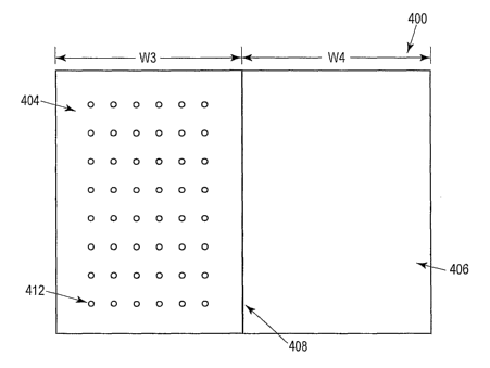
assembled. This pattern or texture of embossing can be seen on a back surface
80 of the
second layer 62 as seen in FIG. 9.
[083] In another embodiment, any of the above disclosed substrates may be
delivered to
the consumer in roll form as seen in FIG. 14 so that the consumer may cut the
product to a
desired length and/or shape using a cutter bar, scissors, or knife. In a
specific
embodiment, the roll 98 is provided in a box (not shown) with a cutter bar and
the
CA 02515678 2005-08-10
WO 2004/071757 PCT/US2004/003859
processing substrate is preferably of the type having a top cut resistant
layer 100 with
perforated or punched holes 102, a middle absorbent layer 104, and a bottom
barrier layer
106. The top and bottom barrier layers 100 and 106 are both made of
thermoplastic
materials as discussed above. Preferably, but not necessarily, the top and
bottom barrier
5 layers 100 and 106 are of the same width W 1 that defines the width of the
roll and the
absorbent layer 104 has width W2 less than the width Wl of the top and bottom
barrier
layers 100. The layers 100 and 106 are directly sealed together along a length
of the roll
98 from the edges of the roll 107 up to a point 108 adjacent the absorbent
layer 104. The
layers 100 and 106 are sealed together using a heat seal, a bar seal,
adhesive, or any other
10 method known in the art.
[084] Preferably, bands of glue 109 are placed across the width of the roll 98
at
increments along the roll 98, wherein the glue bands 109 seal the layers 100
and 106
together at points where the layer 104 is interrupted. The roll 98 can be cut
or torn along
any of the bands 109 to create a processing substrate of a desired length. If
the product is
15 cut or torn along a portion proximate to a center of the glue bands 109,
the glue bands 109
form a complete seal 110 around the absorbent layer 104 to prevent leakage of
fluids out
of edges 112 of the processing substrate. If desired, the product may have
perforations
114 as seen in FIG. 15 preferably located in the center of the glue bands 109
that allow the
consumer to tear off sheets as needed. Alternatively, the product may not
include glue
20 bands, and one or more perforations may be disposed at one or more
locations and extend
through one or more of the layers 100, 104, and 106.
[085] The processing substrate 120 of FIG. 16 is similar to that of FIG. 7
except that the
tissue plies 66 and 72 of FIG. 7 are replaced by crepe paper plies 122 and 124
that together
form an absorbent layer 125 having an enhanced absorbency. Specifically, a
first layer
126 includes a thermoplastic ply 128 disposed above the crepe paper ply 122
wherein
holes 130 are formed at spaced locations and extend through at least the
thermoplastic ply
128. A second layer 132 includes the crepe paper ply 124 disposed above a
thermoplastic
ply 134. The crepe paper plies 122 and 124 provide more space for liquids to
be held in
the absorbent layer 125 of the processing substrate 120. Similarly, as seen in
FIG. 17, the
tissue plies 66 and 72 may be replaced by plies of a paper material having
roughened
surfaces 136 and 138 to increase the net thickness and thereby increase the
holding
capacity of the absorbent layer 125. The roughened surfaces 136, 138 may be
formed by
CA 02515678 2005-08-10
WO 2004/071757 PCT/US2004/003859
21
picking or lifting the surface of paper stock or brushing the paper stock with
a wire roll or
other suitable device.
[086] In yet another embodiment, as seen in FIG. 18, a bilayer single use
processing
substrate 139 comprises a first two-ply cut-resistant layer 140 and a second
two-ply layer
142 similar to the embodiment of FIGS. 5-9. The first layer 140 has a first
surface area
144 and includes a bottom ply 146 which may be a hydrophilic material such as
tissue, an
oleophilic material such as a non-woven polypropylene, or a composite
oleophilic and
hydrophilic material commingled normal to the substrate, for example by
needlefelting,
hydro entanglement, or pneumatic entanglement, and a top thermoplastic cut
resistant ply
148. Apertures 150 preferably extend through the entire first layer 140, but
may extend
only through the top thermoplastic ply 148 of the first layer 140. Optionally,
as seen in
FIG. 19, a ply 158 which may be a hydrophilic material such as tissue, an
oleophilic
material such as a non-woven polypropylene, or a composite oleophilic and
hydrophilic
material such as a needlefelted composite of such materials may be disposed
below the
bottom ply 146 of the top layer 140. Further, a ply selected from the same
group of
materials may be disposed below the top ply 154 of the bottom layer 142.
[087] Other oleophilic materials include THINSULATEOO by 3MC~, polyester,
finely
spun polyolefins, materials coated with clays, or any other known materials,
wherein the
oleophilic material absorbs oil based liquids, such as grease from fried
foods. The second
layer 142 has a second surface area 152 that is preferably (although not
necessarily) larger
than the first surface area 144 and includes a top ply 154 which may be a
hydrophilic
material such as tissue, an oleophilic material such as those disclosed above,
or a
composite oleophilic and hydrophilic material as discussed above, disposed
atop a
thermoplastic barrier ply 156. The thermoplastic material and tissue plies of
both layers
have thicknesses identical or similar to like layers of FIGS. 5-9. The layer
140 may be
centered atop the layer 142 and may be adhered or otherwise joined thereto. It
is
advantageous in the embodiments of FIGS. 18 and 19 to place an oleophilic
layer above a
hydrophilic layer, but is not necessary.
[088] Any of the embodiments as disclosed herein may include an odor absorbing
material within or applied to one or more of the layers. For example, an odor
absorbent
compound may be impregnated or otherwise added to either or both of the tissue
plies, the
crepe paper plies, the roughened paper plies or any other portion of the
absorbent layers)
CA 02515678 2005-08-10
WO 2004/071757 PCT/US2004/003859
22
of the processing substrate. Suitable odor absorbing materials include baking
soda,
activated carbon, talc powder, cyclodextrin, ethylenediamine tetra-acetic
acid, zeolites,
antimicrobial agents, activated silica, activated charcoal, or any other
materials known in
the art. In order to preserve the odor absorbing capacity of the absorbent
layer 170 before
consumer use, one or more strips of tape 172 can be attached to the top layer
174 of the
processing substrate 176 as seen in FIG. 20. The strips) of tape 172 include a
relatively
low-tack adhesive and cover some or all the holes or apertures 178 in the top
layer 174 of
the processing substrate 176 to keep the substrate 176 from absorbing odors
prior to use.
The strips) 172 are removed when a consumer is ready to use the processing
substrate
176.
[089] Also, any or all of the layers of any of the embodiments disclosed
herein may be
tinted or otherwise processed to change color when liquid is exposed thereto.
For
example, the bottom thermoplastic layer of any of the embodiments presented
herein may
be tinted almost any color so that, when the absorbent layer becomes wet and
changes
from opaque to translucent or nearly transparent, the color of the
thermoplastic layer
below the absorbent layer will become apparent. A medium tint of any color
(e.g., purple
or blue) works most appropriately because the color cannot be seen through the
absorbent
layer when the absorbent layer is dry, but the color can be seen when the
absorbent layer is
wet. Alternatively, a slighty darker tint of color may be used wherein the
color can be
seen lightly through the absorbent layer when dry, but is much darker when the
absorbent
layer is wet.
[090] Any of the processing substrates as disclosed herein may also include a
cut-
through indicator as seen in FIG. 21. In a preferred embodiment, a processing
substrate
192 includes a first two-ply cut-resistant layer 194 having a tissue ply 196
disposed below
a thermoplastic ply 198. The first two-ply layer 194 is disposed above a
second two-ply
layer 200 that includes a tissue ply 202 disposed above a thermoplastic ply
204, similar to
the processing substrate of FIG. 7. The processing substrate 192 further
includes a tissue
layer 206 disposed below the thermoplastic ply 204 of the second two-ply layer
200. The
tissue layer 206 may be a paper having a basis weight of 20 pounds per 3000
ft2, but is
preferably a paper having a basis weight of about 10 pounds per 3000 ft2. The
thickness
of the tissue layer 206 is between about 2 mils and about 6 mils thick (0.0508
mm -
0.1524mm). In the event that a user has cut through the plies 196, 198, 202,
and 204,
CA 02515678 2005-08-10
WO 2004/071757 PCT/US2004/003859
23
liquid exuded by the food being cut will be absorbed by the tissue layer 206.
This
absorption can readily be seen by the user so that the user can dispose the
damaged
substrate before damage to the underlying surface occurs and/or a mess has
been made.
[091] In another modification, the processing substrate shown in any of the
previously
discussed FIGS. can be improved to increase the flow of fluid across the
substrate, thereby
allowing for more effective absorption of fluids into the absorption layer.
For example, in
the embodiment seen in FIGS. 6 and 7 the thermoplastic material ply 68 (or any
other ply
and/or layer) can be treated with a wetting agent, such as Dow Corning Q2-5211
Superwetting agent. This treatment could be accomplished before, during, or
after
assembly of the substate layers, and preferably prior to assembly thereof.
Alternatively,
the thermoplastic material ply 68 (or any other ply and/or layer) could be
treated with a
hydrophilic additive, such as Hydrophilic Concentrate VW351 from Polyvel, Inc,
of
Hammonnton. New Jersey. Another option is to utilize an anti-fogging agent,
such
ChemStat AF-1006 from Rutgers Organics of State College, Pennsylvania.
Preferably,
any wetting agent, hydrophilic additive, or anti-fogging agent is of a food
grade. In
another alternative, the thermoplastic material ply 68 is corona treated
(preferably prior to
assembly of the layers), which serves to decrease the surface tension of a
liquid on the top
layer 60 so that such liquid readily flows into the absorbent portions of the
processing
substrate.
[092] The plies and layers of the foregoing embodiments are produced via known
extrusion methods. A first sheet is produced having a cut resistant ply and an
absorbent
ply. Preferably, the cut resistant ply is treated before the two plies are
combined.
Referring now to FIG. 22, an apparatus for and method of applying a wetting
agent,
hydrophilic additive, or anti-fogging agent 256 to the thermoplastic material
ply 68 is
shown. The ply 68 is extruded by an extrusion apparatus 250 onto a chilled
casting roller
252. After being chilled by the casting roller 252, the ply 68 traverses a
path 253 to a pair
of nip rollers 254. Spray nozzles 258 disposed along the path 253 spray a
wetting agent or
hydrophilic additive 256 onto the ply 68. Excess spray from the process can be
collected
in a collecting tray 259 and reprocessed. Once the ply is treated, the cut
resistant ply and
absorbent ply are combined to form a first sheet. A second sheet having a
liquid
impermeable sheet is then attached, preferably by an adhesive, to the
absorbent ply of the
CA 02515678 2005-08-10
WO 2004/071757 PCT/US2004/003859
24
first sheet. Alternatively,'the second sheet also has an absorbent ply and the
two absorbent
plies are attached together.
[093] In an alternative method of application shown in FIG. 23, the ply 68 is
immersed in
a liquid bath 260 containing a wetting agent, hydrophilic additive, or anti-
fogging agent
256. Specifically, the ply 68 is removed from the casting roller 252 by a pair
of nip rollers
254. The pair of nip rollers 254 directs the ply 68 into the liquid bath 260.
Once in the
liquid bath 260, the ply 68 is immersed in the wetting agent or hydrophilic
additive 256
and contacts secondary rollers 255 that direct the ply through the liquid bath
260 and into
a vertical exit path 261. Because the ply 68 exits the liquid bath 260 along
the vertical exit
path 261, any excess wetting agent, hydrophilic additive, or anti-fogging
agent 256 can
easily return to the liquid bath 260.
[094] In yet another embodiment as seen in FIG. 24, a processing substrate 262
may
include a first layer 264 of a paperboard material and a second polymeric
layer 266
disposed below the first layer 264 and which is impervious to liquids.
Preferably,
although not necessarily, the first and second layers 264 and 266,
respectively, are the
same size.
[095] The paperboard material of the first layer 264 preferably, although not
necessarily,
has a dry basis weight of at least 150 pounds per 3000 ft2, and more
preferably a dry basis
weight of at least 200 pounds per 3000 ft2. Although paper is not inherently
cut resistant,
high dry basis weight paperboards begin to exhibit some cut resistant
properties. Any of
the polymeric materials disclosed above can be used to form the second
polymeric layer
266, but low density polyethylene and polypropylene are preferred materials.
The
thickness and sizes of the first and second layers 264 and 266, respectively,
are similar to
equivalent layers of the embodiments discussed herein.
[096] A still further embodiment utilizes different adhesive patterns to
improve liquid
flow from the surface of the substrate. One such adhesive pattern is discussed
above in
relation to FIGS. 5-9. FIG. 25 illustrates another adhesive pattern wherein
the adhesive
lines of FIGS. 5-9 extending continuously from side-to side of the first layer
60 are
replaced by discontinuous adhesive segments 300. The adhesive segments 300 can
be
disposed in any regular or irregular (including random) pattern. In the
illustrated
embodiment, the adhesive segments 300 are substantially all of the same length
and width
and are disposed substantially parallel to one another in a regular pattern
with the
CA 02515678 2005-08-10
WO 2004/071757 PCT/US2004/003859
apertures 76 to form alternating rows of apertures 76 and segments 300.
Preferably, a
regular spacing exists between apertures in an x-direction and a y-direction
such that rows
of apertures are formed. Also preferably, each row of segments 300 is disposed
at a
location equidistant to adjacent rows of apertures 76 (except at the top and
bottom edges
5 of the layer 60) and each row of apertures 76 is disposed substantially
equidistant adjacent
rows of segments 300 (again, except at the top and bottom edges of the layer
60), as seen
in FIG. 25. Thus, for example, a first row 303a comprising a series of
segments 300a1-
300a23 is disposed in a linear fashion substantially midway between rows 301a
and 301b
of apertures 76. Similarly, a second row 303b comprising a further series of
segments
10 300b1-300b24 is disposed in a linear fashion substantially midway between
rows 301b
and 301c of apertures 76. The segments 300a1-300a23 are offset from left-to-
right as seen
in FIG. 25 with respect to the segments 300b1-300b24. Preferably, each
aperture 76 is
disposed above (as seen in FIG. 25) a gap between adjacent ones of the
segments 300 in
the segment row immediately below the aperture 76. In addition, each aperture
76 is
15 disposed below a midpoint of a segment 300 in the segment row immediately
above the
aperture 76. Each of the segments 300 has an effective length (i.e., a side-to-
side
dimension or extent as seen in FIG. 25) less than the width W of the layer 60,
and, more
preferably, greater than the distance between adjacent segments 300 of each
row of
segments 300. The segment and aperture patterns described above are repeated
over the
20 entire surface area of the layer 60. The combination of the segment pattern
and the
aperture pattern results in an advantageous ready dispersion of liquid into
the absorbent
plies of the processing substrate as discussed above. This advantage of this
embodiment
results from the ability of the liquid to flow from an aperture 76 not only
between adjacent
rows of segments 300, but also through spaces between individual segments 300
of a row.
25 [097] In an alternative embodiment, the adhesive portions could be applied
to the sheet
in continuous lines and then areas of those lines between the adhesive
segments 300 may
be removed or rendered ineffective as an adhesive prior to securing the layers
together.
As in the previous embodiment, this results in a processing substrate wherein
liquid can
flow through the absorbent plies between adhesive segments of the same row, as
well as in
the spaces between rows of adhesive segments. Thus, liquid can spread in as
many
directions as possible from the apertures 76.
CA 02515678 2005-08-10
WO 2004/071757 PCT/US2004/003859
26
[098] Also shown in FIG. 25 are two border adhesive strips 304 disposed
parallel with
and extending the width of the first layer 60. While the border adhesive
strips 304
strengthen the edge bond between layers they are not a requirement. Also, as
shown in
FIG. 26, there may be two additional border strips extending the length of the
first layer 60
to provide additional strengthening of the layer edge bond.
[099] Referring now to FIGS. 27 and 28, methods for applying the adhesive to
the
substrate are shown. The first layer 60 and second layer (not shown) are
produced as
discussed above. Then the adhesive segments 300 are applied. In FIG. 27 the
adhesive
segments 300 are applied to the tissue or liquid absorbent ply 66 of the first
layer 60. The
application method includes the step of using an applicator 310 to deposit
regular. sized
portions of adhesive onto the first layer 60 at regular intervals. The second
layer is then
attached to the tissue ply 66. Alternatively, the adhesive could be applied to
the second
layer in a similar manner and the layers and can be assembled together.
[0100] FIG. 28 shows a different method for applying adhesive. In this method
the
adhesive 301 is applied in continuous strips 312 and then portions 302 of the
strips 312 are
removed or rendered ineffective by a roller 316. The roller 316 includes
circumferentially
spaced lands or ridges 318 that extend outwardly from a main roller body 320.
The ridges
318 are brought into contact with the first layer 60 as the roller 316 is
rotated and the strip
312 of adhesive 301 is removed or rendered ineffective (i.e., non-flowable
and/or non-
sticky) where the ridge 318 makes contact therewith. This can be accomplished
in a
variety of ways. In one embodiment, simple contact and/or compression by the
ridge 318
causes the adhesive to be driven into the absorbent ply of the layer away from
the surface
thereof. Alternatively, such contact and/or compression may cause the adhesive
to adhere
to the ridge 318 and to be removed from the first layer 60. The portions may
be removed
from the ridges 318 by cryogenic cleaning using dry carbon dioxide or
nitrogen. In a
further embodiment, a chemical or other agent carried by the ridges bonds with
the
adhesive 301 so that the adhesive is unable to adhere to another object. This
agent could
be of an organic or inorganic nature such as: talc; a silicon dioxide powder;
flour or other
starch composition; sawdust; paper fibers; a silicone mold release agent; or
any anti-stick
compounds such as canola oil, cooking sprays, or a TEFLON~ agent. In any case,
one or
more portions 302 of each strip 312 are "deactivated" as noted above (i.e.,
rendered
ineffective) so that when the first and second layers are assembled together,
the adhesive
CA 02515678 2005-08-10
WO 2004/071757 PCT/US2004/003859
27
in the deactivated zones fails to spread into the absorbent ply of the
adjacent layer at such
locations, thereby preventing the formation of liquid impervious zones at the
areas where
the ridges contacted the adhesive strip. As a result, liquid subsequently
applied to the
substrate liquid can spread out in a substantially radial pattern from each
aperture.
[0101] Any other suitable method of removing or "deactivating" the adhesive
can be used,
as desired, to produce one or more discontinuous adhesive segments each having
effective
side-to-side dimensions (as seen in FIGS. 25 and 26) less than the width of
the sheet 60. If
desired, as seen in FIGS. 25 and 26, the segments may be separated from one
another by
distances less than the lengths of the segments.
[0102] As seen in FIGS. 29 and 30, a processing substrate 338 may include an
absorbent
material layer 340 and randomly spaced strands of material 342 that are
substantially
continuous and preferably a thermoplastic material disposed on a first side
344 of the
absorbent material layer 340. The randomly spaced strands 342 preferably
provide a top
surface that is cut resistant and liquid pervious. Almost any type of
thermoplastic material
can be used to form the randomly space strands 342, including but not limited
to,
polyolefins such as polyethylene and polypropylene, polyvinyl chloride,
polycarbonate,
polylactic acid, thermosetting materials, or any type of thermoplastic
material with an
additive or filler such as clay. Note that non-thermoplastic materials are
possible, but may
not provide the necessary cut resistant properties. The strands 342 may
further be almost
any size in diameter ranging from about 20 microns to about 4 mm, depending on
the use
of the processing substrate.
[0103] The processing substrate 338 may also include a barrier layer 346
attached to a
second side 348 of the absorbent material layer 340 as seen in FIG. 31. The
barrier layer
346 comprises a single polymeric or thermoplastic material ply 350, as
discussed in detail
above. Alternatively, as seen in FIGS. 32 and 33, the barrier layer 346
includes a
polymeric or thermoplastic material ply 350 disposed below an absorbent
material ply
352, also discussed in detail above. Further, the randomly spaced strands 342
and
absorbent layer have a surface area 354 that is smaller than a surface area
356 of the
barrier layer 346.
[0104] The method of producing the processing substrates of FIGS. 29-33 as
seen in FIG.
34 includes the steps of providing the absorbent material layer 340 and moving
the
absorbent material layer 340111 a first direction 360. Thereafter, the method
includes the
CA 02515678 2005-08-10
WO 2004/071757 PCT/US2004/003859
28
step of depositing the randomly spaced strands of thermoplastic material 342
onto the first
side 344 of the absorbent material layer 340 to form the necessary surface
thereon. As the
absorbent material layer 340 moves in the first direction past an extrusion
die 362, the
randomly spaced strands 342 are deposited through multiple spinnerets or small
orifices
364 onto the first side 344 of the absorbent material layer 340. The randomly
spaced
strands 342 may be deposited on the entirety of the absorbent material layer
340 or a
smaller portion of the absorbent material layer 340 as seen in FIGS. 32 and
33.
[0105] The extrusion die 362 is fixed relative to the first direction but may
move with
respect to a second direction 366 that is perpendicular to the first
direction. Preferably, the
extrusion die 362 rotates and oscillates as it is extruding the strands 342
onto the absorbent
material layer 340 to create the randomized pattern of strands 342.
Optionally, several
extrusion dies 362 may be used at various points in the path of the moving
absorbent
material layer 340. Still further, air pressure through the use of pneumatic
air devices may
be used to manipulate the division of the strands of material 342.
[0106] Thereafter, the randomly spaced strands 342 may optionally be
calendared to form
flattened strands with spaces or voids therebetween. This step creates a
flattened surface
and fills in some of the void space between strands 342. Also optionally, a
barrier layer
346 may be joined to the second side 348 of the absorbent material layer 340
by extrusion
coating, adhesive, or any other process as discussed in detail above. As also
discussed
above, the barrier layer 346 may comprise a single thermoplastic ply 350, a
thermoplastic
ply 350 disposed below an absorbent ply, or any other combination of layers or
plies.
[0107] According to a further embodiment as seen in FIGS 35-37, a polymeric
sheet
material 400 may be used to configure a processing substrate 402 for
preparation of food
or other articles thereon. The polymeric sheet material 400 generally includes
a liquid
pervious top or upper section 404 having a cut resistant upper surface 414,
and a liquid
impermeable bottom or lower section 406 that is integral with the upper
section 404.
Preferably, the width W3 of the upper section 404 and the width W4 of the
lower section
406 are equal, but it is possible that one of the widths W3, W4 is larger than
the other.
Also preferably, both the upper and lower sections 404 and 406, respectively,
are made of
any of the thermoplastic materials discussed in detail above. They are
preferably the same
material but may be manufactured of different materials to vary the
characteristics of the
upper and lower sections 404 and 406.
CA 02515678 2005-08-10
WO 2004/071757 PCT/US2004/003859
29
[0108] A consumer preferably would configure the processing substrate 402 by
folding
the upper section 404 over the lower section 406 along a fold line 408.
Optionally, the
fold line 408 may be in the form of a score line to facilitate the folding
process. If a score
line is used, grooves are formed in the polymeric sheet material 400 along the
fold line
408 for ease in folding. Depending on the level of absorbency desired,
absorbent material
410, such as one or more paper towels, may thereafter be inserted between the
upper and
lower sections 404 and 406 of the processing substrate 402 to absorb liquids
generated
during the use of the processing substrate 402.
[0109] The cut-resistant upper section 404 is preferably made of a layer
sufficiently
durable to withstand aggressive cutting of meats, vegetables and other food
items by a
serrated or non-serrated blade. Preferably, the upper section 404 includes a
plurality of
spaced apart apertures 412 to permit the passage of liquids through the upper
section 404
into the absorbent material 410 when configured as a processing substrate 402.
The
apertures 412 may be formed by punching, perforating, or any other means known
in the
art and may have any pattern as discussed above.
[0110] Also, it is generally preferred that the upper section 404 have a
roughened or
textured upper surface 414 to prevent slippage of items during processing of
items
thereon. A lower surface 416 of the upper section 404 may also be roughened or
textured
to help secure the absorbent material 410 in place within the folded
processing substrate
402. The roughened or textured surfaces may be created using techniques, such
as
embossing, creating a pattern thereon, or any other techniques discussed
herein or known
in the art.
[0111] The lower section 406, is preferably made of a liquid and bacteria
impermeable
material to prevent leakage of liquids and transfer of bacteria onto a work
surface. The
lower section 406 is preferably made of a slip-resistant material to prevent
slippage of the
processing substrate 402 on the work surface. Alternatively, a lower surface
418 of the
lower section 406 may be roughened or textured similar to that of the lower
surface 416 of
the upper section 404 to prevent slippage of the lower section 406 of the
processing
substrate 402 on the work surface. An upper surface 420 of the lower section
406 may
also be roughened or textured to secure the absorbent material 410 in place
within the
processing substrate 402. The roughened or textured surfaces may be created
using
CA 02515678 2005-08-10
WO 2004/071757 PCT/US2004/003859
techniques described in detail above. If multiple surfaces are roughened or
textured, they
may have the same roughness or texture or different roughnesses or textures.
[0112] In yet another embodiment, an adhesive may be applied to the lower
surface 418 of
the lower section 406 such that the lower surface 418 adheres to a work
surface wherein
5 the processing substrate 402 is used, thereby preventing slippage of the
processing
substrate 402 during processing thereon. Optionally, the adhesive may be
applied to the
upper surface 420 of the lower section 406 such that when the absorbent
material 410 is
inserted between the upper section 404 and lower section 406, the absorbent
material 410
adheres to the upper surface 420 of the lower section 406, thereby minimizing
slippage of
10 the absorbent material 410 during food processing. As described previously,
the adhesive
may be applied to either the lower surface 418 and/or upper surface 420 of the
lower
section 406 in any number of patterns, including without limitation,
interrupted patterns
such as a series of spaced spots and continuous patterns such as parallel
stripes or
interlocking stripes.
15 [0113] The polymeric sheet material 400 may be extruded with a uniform
thickness across
both the upper and lower sections 404 and 406, respectively. Alternatively,
the polymeric
sheet material 400 may be extruded to produce upper and lower sections 404 and
406
having different thicknesses. For the example, the cut-resistant upper section
404 may
range from about 2 mils (0.0508mm) to about 9 mils (0.2286mm) in thickness and
the
20 liquid-impermeable lower section 406 may range from about 2 mils (0.0508mm)
to about
9 mils (0.2286mm) in thickness.
[0114] In another embodiment as seen in FIG. 38, a polymeric sheet material
400 includes
an upper section 404 with a textured lower surface 416 and/or a lower section
404 with a
textured upper surface 420. The consumer preferably would fold the upper
section 404
25 over the lower section 406 along the fold line 408, thereby placing the
textured surfaces in
contact with each other to create the processing substrate 402. The texture of
the upper
surface 420 andlor lower surface 416 facilitate the retention of waste liquids
therebetween
during the food preparation process, thereby eliminating the need for
inserting absorbent
material within the folded processing substrate 402.
30 [0115] In another embodiment as seen in FIG. 39, the polymeric sheet
material 400 of
FIG. 35 may be delivered to the consumer in a roll 422 similar to that of FIG.
14. The
consumer may cut a portion of the polymeric sheet material 400 from the roll
422 at a
CA 02515678 2005-08-10
WO 2004/071757 PCT/US2004/003859
31
desired length andlor shape using a cutter bar, scissors, or knife.
Preferably, the roll 422
includes perforations 424 at spaced locations so that the roll 422 can be cut
or torn along
any of the perforations 424 to create a processing substrate of a desired
length. Thereafter,
the consumer preferably would fold the sheet along the fold line 408 disposed
along a
length L of the roll 422 to process items thereon.
[0116] Further specific examples of structures are given below:
[0117] Example 1 - a trilayer structure wherein the layer 16 comprises 5 mil
(0.127rmn)
thick PP, filled with up to 40% mica and including 1/32" diameter holes with 9
holes/square inch. The layer 18 is a 37# airlaid cellulose mat thermally
laminated to a 5
mil (0.127mm) thick PP backing sheet comprising layer 20. The layer 16 is
thermally
bonded to the layer 18.
[0118] Example 2 - a bilayer structure comprising a nonwoven polyolefin fabric
upper
layer point bonded to a second layer of polymeric film that functions both as
a barrier and
as a cut resistant surface. During manufacture a food-contact approved
surfactant may be
applied to the upper layer to provide a desired hydrophilic characteristic.
[0119] Example 3 - a scrim made of any of a variety of materials, such as a
thermoplastic
or thermosetting polymeric material having voids between portions of material
is post-
filled with absorbent material, such as cellulose, using any suitable post-
filling process,
such as a wet-laid process or a vacuum process, to form a mat. A barrier layer
of any
suitable material (e.g., PP or PE) is thereafter applied in any suitable
manner, such as by
extrusion lamination, to an undersurface of the mat and the mat is thereafter
subjected to
an embossing process either while the barrier layer is still partially molten
and/or as heat is
applied to cause the barrier layer to bond securely to the scrim.
[0120] Example 4 - a bilayer single use processing substrate comprises a first
layer 60,
wherein the tissue ply 66 is 2.5 mils (0.0635mm) thick and the thermoplastic
material ply
68 is 5 mils thick (0.127mm). The second layer 62 has a tissue ply 72 which is
2.5 mils
(0.0635mm) thick and a thermoplastic material ply 74 which is 3.5 mils
(0.0889mm) thick,
wherein the first layer 60 is secured atop the second layer 62 by an ethyl
vinyl acetate
adhesive.
[0121] Each of the thermoplastic material plies consists of a resin comprising
an isotactic
copolymer metallocene polypropylene, wherein the metallocene polypropylene
comprises
99.9 percent by weight of a propylene monomer and 0.1 percent by weight of an
ethylene
CA 02515678 2005-08-10
WO 2004/071757 PCT/US2004/003859
32
monomer. The resin comprises 93.873 percent by weight of the metallocene
polypropylene, 6.050 percent by weight of a talc additive, 0.055 percent by
weight of
calcium stearate, 0.011 percent by weight of a primary antioxidant, and
0.011percent by
weight of a secondary antioxidant.
[0122] The first and second layer tissue plies 66, 72 comprise 98 percent by
weight of a
virgin hardwood and softwood wood pulp, 0.2 percent by weight of a polyamide
wet
strength resin and trace amounts of a defoamer, a dryer release agent, two
creping agents,
a repulping aid and a bleach neutralizer.
[0123] The first layer 60 has dimensions of 9.75 inches (247.65mm) by 7.688
(195.275mm) inches and the second layer 62 has dimensions of 11.75 (298.45mm)
inches
by 9.688 inches (246.075mm). The first layer 60 includes 414 regularly spaced
apertures
created by having a nominal diameter of 0.08 inches (2.032mm), wherein the
apertures
form a zigzag pattern and are separated from one another by 0.279 inches
(7.0866mm) in
the x-direction and 0.165 inches (4.191mm) in the y-direction. The average
number of
apertures per square inch is 5.52.
[0124] The first surface area 64 and the portion of the second surface area 70
disposed
outside of the first surface area are embossed with embossing pattern 78.
[0125] One or more of the following benefits may be obtained, depending upon
the choice
of material(s), properties and material amounts:
1. the sheet absorbs food juices while cutting and reduces resulting mess;
2. the sheet is easy to dispose of;
3. the sheet reduces or even prevents accidental germ/microbial contamination
because the genus from one food item will not get transferred to another if
the cutting
sheet is disposed of after use;
4. the sheet provides cut resistance, i.e., it helps reduce any cut damage to
the
kitchen or other work surface;
5. the sheet does not allow food juices to run all over the work surface;
6. the sheets may be provided in varying sizes to suit the cutting or other
task;
7. the sheet may be used on top of a cutting board or directly on the work
surface;
8. the sheet reduces slippage, by providing a skid-resistant contact with the
work
surface;
CA 02515678 2005-08-10
WO 2004/071757 PCT/US2004/003859
33
9. after cutting, one need only lift the sides of the sheet to funnel food
into a
cooking pot;
10. the sheet can be set on a surface to catch debris and grease;
11. the sheet is easily rolled up with waste captured therein and disposed of
in the
trash can;
12. since each sheet is clean the need for repeated cleaning of the cutting
board or
other work surface is avoided;
13. the sheet can be used to cut or process any food or other material
including
meat, chicken, fish, soft or hard fruits and vegetables, dough, etc...;
14. unlike using a paper towel, the sheet does not permit fiber and lint to
become
attached to the food being cut.;
15. the sheet does not transfer any smell or taste to the product being cut or
otherwise processed (alternatively, the sheet could be impregnated with a
desirable scent,
such as lemon, which is then transferred to the item being processed);
16 the sheet manages bacteria by absorption, containment and barrier rather
than
by the use of added chemicals;
17. the sheet can be made food contact approved;
18. the top surface reduces slippage of food while cutting;
19. the cutting surface will not dull knives like some hard cutting surfaces;
20. the sheet is hygienic;
21. the sheet may be formed with at least one and, preferably multiple
absorbent
edges that give an extra measure of security to manage bacteria-borne juices;
22. the sheet offers superior food/surface protection for non-cutting food
preparation applications;
23. the sheet affords an easy, convenient medium for in-home or out-of home,
recreational and outdoor uses;
24. the sheet can be cut by consumers to other sizes and/or shapes;
25. the sheet can be held in place on countertops by a few drops of water;
26 the sheet protects the countertop and food from potentially deadly
pathogens
that cannot be seen;
27 the sheet allows safer food preparation for the consumer and the consumer's
family by reducing the risk of food-borne illness;
CA 02515678 2005-08-10
WO 2004/071757 PCT/US2004/003859
34
28. the sheet can reduce food preparation time;
29 the profile and/or texture of the cutting surface can be customized to
provide
benefits not practical in conventional cutting surfaces or boards simply
because such
articles would be difficult or impossible to wash;
30 the sheets do not take up room in the dishwasher or in the bags and wraps
drawer of the kitchen;
31. in alternative embodiments bacteria borne liquids are securely trapped in
cells
and/or a layer below the cutting surface;
32. the sheet may be constructed so that the consumer can see the absorption
of
liquid;
33. the sheet may be made to have a clean hygienic appearance;
34. the sheet may have a decorative appearance that is printed and/or embossed
as
desired;
35. the sheet absorbs like a paper towel, but has the additional advantages of
barrier and cut resistance;
36. the sheet has additional uses, for example, as a placemat, as counter
protection
for use around stove/cook top, bin/shelf protection in refrigerator, under dog
or cat dish,
under plants, under laxge serving dishes, etc. . .;
37. in some embodiments the sheet has a place to wipe a knife on;
38. the sheet can make a desirable addition to a picnic basket;
39. the sheet can be used to line a refrigerator meat tray;
40. the sheet absorbs and contains all juices from defrosting meat;
41. the sheet can contain odors from foods, such as fish;
42. the sheet can be used on dishes and platters to prevent scratching of same
by
knives;
43. the sheet can be placed under sticky and dripping containers in
refrigerator ;
44. the sheet does not fall apart like paper towels; and
45. the sheet could be used as a drawer liner or as a mat to do art projects
on.
Industrial Applicability
[0126) The present invention is not limited to the concept of utilizing and
constructing
disposable, absorbent barrier surfaces in place of and/or in conjunction with
conventional
CA 02515678 2005-08-10
WO 2004/071757 PCT/US2004/003859
cutting boards, but encompasses all food handling, article support and
barrier/isolation
applications where absorbent, liquid/bacteria barrier management is desirable
and methods
for making the same.
[0127] Numerous modifications to the present invention will be apparent to
those skilled
in the art in view of the foregoing description. Accordingly, this description
is to be
construed as illustrative only and is presented for the purpose of enabling
those skilled in
the art to make and use the invention and to teach the best mode of carrying
out the same.
The exclusive rights to all modifications which come within the scope of the
appended
claims are reserved.