Language selection

Search

Patent 2515751 Summary

Third-party information liability

Some of the information on this Web page has been provided by external sources. The Government of Canada is not responsible for the accuracy, reliability or currency of the information supplied by external sources. Users wishing to rely upon this information should consult directly with the source of the information. Content provided by external sources is not subject to official languages, privacy and accessibility requirements.

Claims and Abstract availability

Any discrepancies in the text and image of the Claims and Abstract are due to differing posting times. Text of the Claims and Abstract are posted:

  • At the time the application is open to public inspection;
  • At the time of issue of the patent (grant).
(12) Patent: (11) CA 2515751
(54) English Title: ROLLER ADJUSTMENT APPARATUS FOR AN EXTRUSION MILL
(54) French Title: APPAREIL DE REGLAGE DE ROULEAUX POUR LAMINOIR D'EXTRUSION
Status: Expired
Bibliographic Data
Abstracts

English Abstract


In a roller adjustment
apparatus for an extrusion mill,
comprising a cylindrical die (2) with
radially extending extrusion channels
and a number of rollers (1) within
the die, rotatable about their axes and
co-operating with the die to press
material to be treated through the
extrusion channels in the die wall,
the adjustment apparatus comprises
eccentrically journalled bearing
shafts (3) for mounting the rollers
(1), said eccentrically journalling
of the shafts (3) providing a radial
adjustment of the position of the
rollers (1) relative to the die (2),
the rotation of the eccentrically
journalled shafts (3) is provided
by means of extension arms (6)
fixedly mounted on the ends of the
eccentrically journalled shafts (3),
and said extension arms (6) being
connected to an axially movable
connection element (8) by means of
articulated connected linkage rods
(7), and said connection element (8) being connected to a rod (9) provided
with its axis in the axis of the die (2) and extending to a
position outside the material flow of the extrusion mill to move the
connection element (8) in the direction of the axis of the die
(2), said axial movement being provided manually or by means of a suitable
actuator connected to the rod (9). In this way, only
simple mechanical components, such as linkage rods (7) and connection elements
(8) are positioned close to the rollers and these
components are moved by manual adjustment or by means of suitable actuators
positioned outside the aggressive environment
close to the rollers of the extrusion mill.


French Abstract

L'invention concerne un appareil de réglage de rouleaux pour laminoir d'extrusion, qui comprend une matrice cylindrique (2) dotée de canaux d'extrusion s'étendant radialement et un certain nombre de rouleaux (1) contenus dans la matrice, qui peuvent tourner autour de leur axe et coopèrent avec la matrice pour presser la matière destinée à être traitée à travers les canaux d'extrusion ménagés dans la paroi de matrice. L'appareil de réglage comprend des arbres de roulement (3) disposés rotatifs de manière excentrée, destinés au montage des rouleaux (1), ladite disposition rotative des arbres (3) assurant un réglage radial de la position des rouleaux (1) par rapport à la matrice (2). La rotation des arbres (3) disposés rotatifs de manière excentrée est assurée par des bras d'extension (6) montés de manière fixe sur les extrémités des arbres (3) disposés rotatifs de manière excentrée, et lesdits bras d'extension (6) sont reliés à un élément de liaison (8) axialement mobile au moyen de tiges de liaison (7) reliées et articulées. Ledit élément de liaison (8) est relié à une tige (9) dont l'axe se trouve dans l'axe de la matrice (2), et s'étend vers l'extérieur du flux de matière du laminoir d'extrusion, afin que l'élément de liaison (8) soit déplacé dans la direction de l'axe de la matrice (2), ledit mouvement axial étant effectué manuellement ou à l'aide d'un actionneur approprié relié à la tige (9). De cette façon, seuls des éléments mécaniques simples, tels que des tiges de liaison (7) et des éléments de liaison (8), sont placés à proximité des rouleaux, et ces éléments sont déplacés par un réglage manuel ou au moyen d'actionneurs appropriés placés à l'extérieur de l'environnement agressif se trouvant à proximité des rouleaux du laminoir d'extrusion.

Claims

Note: Claims are shown in the official language in which they were submitted.


5
CLAIMS
1. Roller adjustment apparatus for an extrusion mill, in particular a pellet
mill,
comprising
a cylindrical die (2) with radially extending extrusion channels and a number
of
rollers (1) within the die (2), rotatable about their axes and co-operating
with the die
to press material to be treated through the extrusion channels in the die
wall, with
driving means to rotate the die (2) and the axes of the rollers (1) relative
to each
other about the axis of the die (2), said adjustment apparatus comprising
eccentrically journalled bearing shafts (3) for mounting the rollers (1), said
eccentrically journalling of the shafts (3) providing a radial adjustment of
the position
of the rollers (1 ) relative to the die (2) by rotation of the eccentrically
journalled
shafts(3), characterised by
the rotational adjustment of the eccentrically journalled shafts (3) being
provided by
means of
extension arms (6) fixedly mounted on the ends of the eccentrically journalled
shafts
(3), said extension arms (6) being connected to an axially movable connection
element (8) by means of articulated connected linkage rods (7), and said
connection
element (5) being connected to a rod (9) provided with its axis in the axis of
the die
(2) and extending to a position outside the material flow of the extrusion
mill to move
the connection element (8) in the direction of the axis of the die (2), said
axial
movement being provided manually or by means of a suitable actuator connected
to
the rod (9).
2. Roller adjustment apparatus in accordance with claim 1, characterised
by the linkage rods (10) being provided in the form of turnbuckles (7).
3. Roller adjustment apparatus in accordance with claim 1 or 2, character-
ised by the linkage rods (10) being arranged to be positioned perpendicular to
the
axis of the die (2), when the rollers (1) are adjusted to the position closest
to the die
(2).
4. Roller adjustment apparatus in accordance with any of the preceding claims,
characterised by the actuator connected to the rod (9) being provided in the
form of a hydraulic cylinder-piston unit.


6
5. Roller adjustment apparatus in accordance with any of the preceding claims,
characterised by the actuator connected to the rod (9) being provided in the
form of a linear actuator of the lead screw type.
6. Roller adjustment apparatus in accordance with any of the preceding claims,
characterised by the actuator connected to the rod (9) being positioned on
that side of the extrusion mill, which is opposite the inlet for the material
to be
treated.
7. Roller adjustment apparatus in accordance with any of the preceding claims,
characterised by the number of rollers (1) inside the cylindrical die (2)
being
between one and six.
8. Roller adjustment apparatus in accordance with claim 7, characterised
by the number of rollers (1) inside the cylindrical die (2) being two or
three.

Description

Note: Descriptions are shown in the official language in which they were submitted.


CA 02515751 2005-08-12
WO 2004/073963 PCT/DK2003/000115
1
ROLLER ADJUSTMENT APPARATUS FOR AN EXTRUSION MILL
TECHNICAL FIELD
The present invention relates to a roller adjustment apparatus for an
extrusion mill of
the kind set forth in the preamble of claim 1.
BACKGROUND ART
In extrusion mills it is known to provide some kind of adjustment of the
distance
between the rollers and the die and to provide a possibility of performing the
adjustment during operation, in order to optimise the pelletising process. The
known
apparatus for performing such adjustments provides the adjustment by using
hydraulic cylinders directly connected to the roller shafts, as shown in US-
4,361,529
or provides the adjustmenfi via a rotational shaft positioned in the axis of
the mill and
connected to the roller shafts via a cam plate or gear mechanisms, as shown in
EP-
233,147 or EP-594,273.
DISCLOSURE OF THE IN!/ENTION
ft is the object of the present invention to provide a roller adjustment
apparatus of
the kind referred to above, with which it is possible to avoid positioning of
sensitive
mechanical components close to the rollers, where an aggressive environment is
present, and this object is achieved with a roller adjustment apparatus of
said kind,
which according to the present invention also comprises the features set forth
in the
characterising clause of claim 1. With this arrangement, only simple
mechanical
components such as linkage rods and connection elements are positioned close
to
the rollers and these components are moved by manual adjustment or by means of
suitable actuator means positioned outside the aggressive environment close to
the
rollers of the extrusion mill. Preferred embodiments of the roller adjustment
apparatus, the advantages of which will be evident from the following detailed
description, are revealed in the sub-ordinate claims.


CA 02515751 2005-08-12
WO 2004/073963 PCT/DK2003/000115
2
BRIEF DESCRIPTION OF THE DRAWINGS
In the following detailed part of the present description, the invention will
be
explained in more details with reference to the exemplary embodiment of a
roller
adjustment apparatus in accordance with the invention shown in the drawings,
in
which
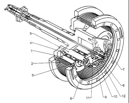
Figure 1 shows a partly cut-up perspective view of the roller adjustment
apparatus in
an extrusion mill comprising two rollers,
Figure 2 shows the apparatus of Figure 1 seen from one end,
Figure 3 shows the apparafius of Figures 1 and 2 in cross section along the
line III-III
in Figure 2, and
Figures 4 and 5 schematically show a corresponding apparatus in an extrusion
mill
comprising three rollers.
DESCRIPTION OF THE PREFERRED EMBODIMENT
The apparatus shown in Figure 1 comprises the major park of an extrusion mill
for
palletising fioodsfiuff of different kinds. The extrusion mill comprises a
cylindrical die
(2) with radially extending extrusion channels and a number of rollers (1 ),
in Figures
1-3 the number of rollers is two. The rollers (1 ) are mounted for rotation
about their
axes and to co-operate with the cylindrical die (2) to press material to be
treated
through the extrusion channels in the die wall. The means for driving (not
shown)
provides a rotation of the cylindrical die (2) and the axes of the rollers (1)
relative to
each other about the axis of the cylindrical die (2). The rollers (1 ) are
mounted on
bearing shafts (3), said bearing shafts (3) being eccentrically journalled in
bores in a
rear roller support flange (4) and a front roller support plate (5), said rear
and front
roller support flange and plate being mutually connected by means of
connection
elements positioned between the rollers (1). The eccentrical journalling of
the shafts
(3) provides the possibility of obtaining a radial adjustment of the positions
of the
rollers (1 ) relative to the cylindrical die (2) by rotation of the
eccentrically journalled
shafts (3). In order to provide the rotational adjustment of the eccentrically
journalled
shafts (3), extension arms (6) are fixedly mounted on the ends of the
eccentrically
journalled shafts (3), and said extension arms (6) are connected to an axially


CA 02515751 2005-08-12
WO 2004/073963 PCT/DK2003/000115
3
movable connection element (8) by means of articulated connected linkage rods
(7)
in the form of turnbuckles, said turnbuckles providing a possibility of
performing a
zero point adjustment of the position of the rollers (1 ) relative to the
cylindrical dies
(2). The connection element (8) is connected to a rod (9) provided with its
axis in the
axis of the cylindrical die (2) and extending to the outside of the extrusion
mill, where
it is connected to suitable actuator means.
The relative rotation of the rollers (1 ) and the cylindrical die (2) can be
provided by
keeping the bearing shafts (3) for the rollers (1 ) stationary and rotating
the cyfindricaf
die (2) or vice versa keeping the cylindrical die (2) stationary and rotating
the
bearing shafts for the rollers (1 ), in which case a rotational linkage will
have to be
provided between the actuator and the connection element (8), possibly at the
actuator end of the rod (9).
As can be seen from Figure 3, the axial movement of the connection element (8)
provides a rotational movement of the eccentrically journalled shafts (3),
which
results in a movement of the rollers (1 ) towards or away from the cylindrical
die (2),
whereby the distance between the rollers (1 ) and the die (2) can be adjusted
in
accordance with the desired function of the extrusion mill. The turnbuckles
(7)
provide a possibility of adjusting a zero point position of the rollers (1 )
and the
adjusted position can be secured by means of suitable nuts mounted on the
turnbuckles (7). The connection between the turnbuckles and the connection
element and the extension arms, respectively, is provided in the form of a
ball joint
(11, 12) connected to the bolts of the turnbuckle (10), thus providing an
articulated
connection between the extension arms (6) and the connection element (8).
Preferably the mechanism is dimensioned and adjusted in such a way that the
turnbuckles (7) are positioned perpendicular to the axis of the cylindrical
die (2)
when the rollers (1 ) are in a position as close as possible to the
cylindrical die (2),
yet without metallical contact between the rollers (1) and the cylindrical die
(2). This
provides a transmission between the actuator and the position of the rollers
(1) with
a maximum force when the roller (1 ) is close to the cylindrical die (2) and
furthermore a fine adjustment possibility for the distance between the roller
(1 ) and
the cylindrical die (2) with high precision when the roller (1 ) is close to
the cylindrical
die (2).


CA 02515751 2005-08-12
WO 2004/073963 PCT/DK2003/000115
4
This last feature can be further supported by having the eccentricity of the
eccentrically journalled bearing shafts (3) close to the top point in the
situation
where the rollers (1 ) are close to the cylindrical die (2).
Above, the invention has been described in connection with a preferred
embodiment
thereof, but several modifications can be envisaged without departing from the
following claims, such deviations comprising the provision of another number
of
rollers (1), the preferred number of the rollers being two or three.
Furthermore, the
actuator connected to the rod (9) can be provided in the form of a hydraulic
or
pneumatic piston cylinder unit, a linear actuator of the lead screw type, or
any other
type of actuator suitable for the purpose. Manual adjustment of the position
of the
rod (9) could also be envisaged. Also the position of the actuator could be
altered,
e.g. to a position inside the shaft (4), in which situation the rod (9) may be
the piston
rod of a piston cylinder unit, or at the side opposite the shaft (4~).

Representative Drawing
A single figure which represents the drawing illustrating the invention.
Administrative Status

For a clearer understanding of the status of the application/patent presented on this page, the site Disclaimer , as well as the definitions for Patent , Administrative Status , Maintenance Fee  and Payment History  should be consulted.

Administrative Status

Title Date
Forecasted Issue Date 2010-06-15
(86) PCT Filing Date 2003-02-21
(87) PCT Publication Date 2004-09-02
(85) National Entry 2005-08-12
Examination Requested 2007-09-05
(45) Issued 2010-06-15
Expired 2023-02-21

Abandonment History

There is no abandonment history.

Payment History

Fee Type Anniversary Year Due Date Amount Paid Paid Date
Application Fee $400.00 2005-08-12
Maintenance Fee - Application - New Act 2 2005-02-21 $100.00 2005-08-12
Registration of a document - section 124 $100.00 2005-10-26
Maintenance Fee - Application - New Act 3 2006-02-21 $100.00 2006-03-21
Expired 2019 - Late payment fee under ss.3.1(1) 2006-05-01 $50.00 2006-03-21
Maintenance Fee - Application - New Act 4 2007-02-21 $100.00 2007-02-09
Request for Examination $800.00 2007-09-05
Maintenance Fee - Application - New Act 5 2008-02-21 $200.00 2008-02-01
Maintenance Fee - Application - New Act 6 2009-02-23 $200.00 2009-01-23
Registration of a document - section 124 $100.00 2009-08-28
Maintenance Fee - Application - New Act 7 2010-02-22 $200.00 2010-01-27
Final Fee $300.00 2010-03-24
Maintenance Fee - Patent - New Act 8 2011-02-21 $200.00 2011-02-10
Maintenance Fee - Patent - New Act 9 2012-02-21 $200.00 2012-02-09
Maintenance Fee - Patent - New Act 10 2013-02-21 $250.00 2013-02-04
Maintenance Fee - Patent - New Act 11 2014-02-21 $250.00 2014-02-10
Maintenance Fee - Patent - New Act 12 2015-02-23 $250.00 2015-02-09
Maintenance Fee - Patent - New Act 13 2016-02-22 $250.00 2016-02-08
Maintenance Fee - Patent - New Act 14 2017-02-21 $250.00 2017-02-13
Maintenance Fee - Patent - New Act 15 2018-02-21 $450.00 2018-02-13
Maintenance Fee - Patent - New Act 16 2019-02-21 $450.00 2019-02-11
Maintenance Fee - Patent - New Act 17 2020-02-21 $450.00 2020-02-10
Maintenance Fee - Patent - New Act 18 2021-02-22 $459.00 2021-02-08
Maintenance Fee - Patent - New Act 19 2022-02-21 $458.08 2022-02-07
Owners on Record

Note: Records showing the ownership history in alphabetical order.

Current Owners on Record
ANDRITZ FEED & BIOFUEL A/S
Past Owners on Record
ANDRITZ SPROUT A/S
BLOK, JESPER
SPROUT-MATADOR A/S
Past Owners that do not appear in the "Owners on Record" listing will appear in other documentation within the application.
Documents

To view selected files, please enter reCAPTCHA code :


To view images, click a link in the Document Description column. To download the documents, select one or more checkboxes in the first column and then click the "Download Selected in PDF format (Zip Archive)" or the "Download Selected as Single PDF" button.

List of published and non-published patent-specific documents on the CPD .

If you have any difficulty accessing content, you can call the Client Service Centre at 1-866-997-1936 or send them an e-mail at CIPO Client Service Centre.


Document
Description 
Date
(yyyy-mm-dd) 
Number of pages   Size of Image (KB) 
Cover Page 2005-10-19 1 67
Representative Drawing 2005-08-12 1 42
Abstract 2005-08-12 1 92
Description 2005-08-12 4 185
Drawings 2005-08-12 3 105
Claims 2005-08-12 2 74
Description 2009-08-14 5 224
Drawings 2009-08-14 3 101
Claims 2009-08-14 2 76
Representative Drawing 2010-05-19 1 31
Cover Page 2010-05-19 2 79
Correspondence 2005-08-12 1 24
Correspondence 2005-10-17 1 2
PCT 2005-08-12 10 378
Assignment 2005-08-12 6 145
Assignment 2005-10-26 4 117
Fees 2006-02-21 2 48
Fees 2006-03-21 2 53
Prosecution-Amendment 2007-09-05 2 52
Prosecution-Amendment 2009-03-10 2 39
Correspondence 2010-03-24 2 75
Prosecution-Amendment 2009-08-14 9 388
Assignment 2009-08-28 4 119
Assignment 2009-10-20 3 104