Note: Descriptions are shown in the official language in which they were submitted.
CA 02515926 2014-05-13
CLEANING TOOL HAVING A BRUSH PART,
AN INSERTION PART THEREON AND AN INSERTABLE GRIPPER
FIELD OF THE INVENTION
The present invention relates to a cleaning item for indoor-use having
fibrous material, and more particularly, relates to a cleaning item used by
attaching a brush part having fibrous material to a gripper.
DESCRIPTION OF RELATED ART
As disposable or replaceable conventional indoor cleaning items, there
are items which have a brush part made from fibrous material such as, for
example, tow fiber bundles or sheets cut into strips.
As cleaning tool such as this, for example, a cleaning tool is disclosed in
the Patent Document 1, US Patent Publication No. 898725, wherein a part of
the sheets forming the brush is composed of felt or fiber and is used by
fixing a
handle to a predetermined position between the sheets.
Furthermore, in the Patent Document 2, Japanese Patent Laid-Open
Publication No. '11-235301, a cleaning tool wherein layers made from at least
one of long fibers or strips of sheets are layered and joined by a plurality
of
compound lines on one side or both sides of a base material sheet, and the
base material sheet and this layer are disconnected is disclosed.
CA 02515926 2012-09-21
Still further, in the Patent Document 3, Japanese Patent Publication No.
2002-369783, a cleaning tool which has a brush part wherein the brush part is
a
plurality of long and narrow strips formed from flexible sheets, fiber bundles
and
base material sheet layered and partially joined is disclosed.
However, the cleaning tool in Patent Document 1 is a cleaning tool
which is used by fixing the handle, and the gripper cannot be attached or
removed. Therefore, it is unsuitable as a cleaning tool wherein the main
cleaning part is disposable.
In addition, the cleaning tool in Patent Document 2 is suited for floors
and does not have an inserted part for insertion enabling the attachment and
removal of a gripper.
Furthermore, the cleaning tool in Patent Document 3 has an inserted
part for insertion enabling the attachment and removal of a gripper, but the
fiber
bundles, base material sheet and a retention sheet are joined and integrated
by
heat-sealing in a completely layered state. Therefore, it is necessary to
firmly
join respective components to thick sheets and fiber layers by heat-sealing,
and
in order to prevent the reduction of strength of the joint part due to
excessive
heat-sealing, perform fine adjustment of temperatures and pressure when
heat-sealing.
The present invention has been made with the foregoing issues under
consideration, and the object thereof is to provide a cleaning item wherein
the
insertion part of a gripper can be provided easily and the manufacturing
process
is simple.
SUMMARY OF THE INVENTION
As a result of keen research into resolving the foregoing issues, the
inventors of the present invention have discovered that the foregoing issues
can
2
CA 02515926 2012-09-21
be resolved by separately manufacturing a brush part in the main cleaning part
and
an insertion part for the insertion of an insert part of the gripper and
subsequently
joining the two together, and thereby, completed the present invention. More
specifically, the present invention provides the following: a cleaning item
comprising
a brush part constructed from fibrous material; an insertion part with an
insertion
space into which a gripper is detachably inserted and which is formed by a
pair of
sheets, the insertion part being disposed on the brush part; and a joining
member
which joins the brush part and the insertion part.
According to the cleaning item of the present invention, the main
cleaning item comprises the brush part and the insertion part for the
insertion of a
gripper, each of which are manufactured separately. Additionally, these parts
are
joined by adhesive and the like. Therefore, in the joining process, it is not
necessary
to linearly heat-seal the entire brush part and insertion part, and the
tolerance of the
conditions of heat-sealing in the formation of the brush part and the
insertion part is
high. In addition, because the heat-sealing line of the brush part and the
heat-sealing
line of the insertion part can be designed irrespectively, the degree of
freedom in
design is also high. Furthermore, even if there are irregularities in the
thickness and
shape of the brush part, the shape of the insertion part can be designed
freely and
independently and attached. Still further, because the manufacturing process
is
simple and the number of parts is equal to that of conventional material, the
cleaning
item can be provided at low costs.
In a preferred embodiment said joining member is an adhesive.
According to the present invention, the brush part and the insertion part
can be joined faster, more accurately and at a lower cost.
3
CA 02515926 2012-09-21
Preferably said joining member heat-seals a section in said insertion part
excluding the insertion space and said brush part.
According to the invention, because only a section of the brush part is
integrated with the insertion part, they can be joined without affecting the
degree of
freedom or the shape of the brush part.
Preferably, the gripper comprises: a base portion; and a plurality of
insert parts which extend substantially parallel from the base portion, and
the
insertion part comprises a plurality of spaces into which respective insert
parts can be
inserted.
Accordingly, because the insertion part has a plurality of spaces to which
respective insert parts can be inserted, instances wherein plural insertion
parts of the
gripper exist can also be handled.
In a preferred embodiment, a plurality of insertion parts for the insertion
of a plurality of said insert parts is positioned substantially parallel on
said brush part.
The position of the plural insertion parts can be placed freely according
to the plural insert parts.
The joining member can be hot-melt.
By implementing hot-melt as the joining member, the brush part and the
insertion part can be joined faster, more accurately, and at a lower cost.
In a preferred embodiment, the brush part is a tow fiber bundle and/or
sheets cut into strips.
By implementing tow fiber bundle and/or sheets cut into strips as the
fibrous material, dirt and dust can be gathered more
4
CA 02515926 2012-09-21
efficiently, and a more effective cleaning can be performed.
A manufacturing method is also provided for a cleaning item comprising
a brush part constructed from fibrous material; and an insertion part with an
insertion
space into which a gripper is detachably inserted and which is disposed in the
brush
part; comprising: a brush part formation step for forming the brush part by
joining and
integrating a section of a fibrous material; an insertion part formation step
for forming
the insertion part having the insertion space by layering a pair of sheets and
joining a
section thereof; and a joining step for joining the brush part and the
insertion part.
According to the manufacturing method of the cleaning item of the
present invention, the main cleaning part comprises a brush part and an
insertion
part for the insertion of a gripper, each of which are manufactured
separately.
Additionally, these parts are joined by adhesive.
Therefore, because it is
unnecessary to linearly heat-seal the entire brush part and insertion part,
the
tolerance of the conditions of heat-sealing in the formation of the brush part
and the
insertion part is high. In addition, because the heat-sealing line of the
brush part and
the heat-sealing line of the insertion part can be designed irrespectively,
the degree
of freedom in design is also high. Furthermore, even if there are
irregularities in the
thickness and the shape of the brush part, the shape of the insertion part can
be
designed freely and independently and attached. Still
further, because the
manufacturing process is simple and the number of parts is equal to that of
conventional material, cleaning item can be provided at low costs.
According to the present invention, a cleaning item which can easily set
the insert part of the gripper can be provided.
CA 02515926 2012-09-21
BRIEF DESCRIPTION OF THE DRAWINGS
Fig. 1 is a diagram showing the manufacturing process of the cleaning
item of the first embodiment and is an exploded perspective view of the
inserted
part formation process.
Fig. 2A is a diagram showing the manufacturing 'process of the cleaning
item of the first embodiment and is an exploded perspective view of the brush
part formation process.
Fig. 2B is a diagram showing the manufacturing process of the cleaning
item of the first embodiment and is an exploded perspective view of the brush
part formation process.
Fig. 3 is diagram showing the manufacturing process of the cleaning
item of the first embodiment and is an exploded perspective view of the
joining
process.
Fig. 4 is a perspective view of the cleaning item.
Fig. 5A and 5B are cross-sectional views taken along the X-X direction
in Fig. 4.
Fig. 6 is a diagram showing the manufacturing process of the cleaning
item of the second embodiment and is an exploded perspective view of the -
insertion part formation process embodiment.
Fig. 7 is a diagram showing the manufacturing process of the cleaning
item of the second embodiment and is an exploded perspective view of the
brush part formation process.
Fig. 8 is diagram showing the manufacturing process of the cleaning
item of the second embodiment and is an exploded perspective view of the
joining process.
Fig. 9 is a diagram showing the manufacturing process of the cleaning
item of the third embodiment and is an exploded perspective view of the
insertion part formation process embodiment.
6
CA 02515926 2012-09-21
Fig. 10 is a diagram showing the manufacturing process of the cleaning
item of the third embodiment and is an exploded perspective view of the brush
part formation process.
Fig. 11 is diagram showing the manufacturing process of the cleaning
item of the third embodiment and is an exploded perspective view of the
joining
process.
DESCRIPTION OF THE PREFERRED EMBODIMENT
Each embodiment of an example of the cleaning item of the present
invention is described below based on the drawings. In the description of the
embodiments below, the same reference numbers are affixed to the same
construction requisite and explanations thereof are omitted or simplified.
[First Embodiment]
In Fig. 1 to Fig. 5, the first embodiment of a cleaning item and a
manufacturing method thereof of the present invention are shown. Fig. 1 is a
diagram showing the manufacturing process of the cleaning item and is an
exploded perspective view of the insertion part formation process; Fig. 2A and
Fig. 2B are diagrams showing the manufacturing process of the present
invention and is an exploded perspective view of the brush part formation
process; Fig. 3 is diagram showing the manufacturing process of the cleaning
item and is an exploded perspective view of the joining process; Fig. 4 is a
perspective view of the cleaning item ; and Figs. 5A and 5B are cross-
sectional
views in the X-X direction in Fig. 4. The first embodiment is explained below
in
line with the manufacturing process of the cleaning item.
<Inserted Part Formation Process>
First, as shown in Fig. 1, retention sheet 1 and base material sheet 2
are layered and heat-sealed on the two lines, joining line 7' and the joining
line
7
CA 02515926 2012-09-21
6' which is located roughly at the center thereof, and a joined body 15 is
formed.
Through this, two insertion spaces 13 and 13 are formed between the retention
sheet 1 and the base material sheet 2 by the two lines, insertion part sealing
line
7 and insertion part sealing line 6a. The retention sheet 1 and the base
material sheet 2 are preferably heat-sealable material such as non-woven
fabric,
for example. "Heat-sealing" for forming sealing lines in the present invention
includes, other than heat sealing through simply pressing a heated sealing
bar,
methods such as impulse sealing, high-frequency sealing, and ultrasonic
sealing.
Next, a strip part 8 is formed by slitting the joined body 15 from both
sides, and an insertion part 16 is formed. The strip part does not have to be
formed in the insertion part according to the present invention. In addition,
the
formation method of the insertion part according to the present invention is
not
limited to the insertion part 16, above, but must be joined to a brush part
and the
space for the insertion of the insert part must be formed by a pair of sheets.
<Brush Part Formation Process>
As shown in Fig. 2A, a first fiber bundle 3a made from tow fiber, a r
second fiber bundle 3b made from tow fiber, a third fiber bundle 3c made from
tow fiber, a fourth fiber bundle 3d made from tow fiber, and strip sheet 5 on
which a plurality of strips are formed are layered in sequential order. Then,
all
five sheets are joined by heat-sealing on joining line 6', and a brush part 17
is
formed. In other words, in this brush part 17, all layers are integrated by a
brush sealing line 6b.
In the present invention, the brush sealing line, above, is not limited to
one sealing line, and for example, as shown in Fig. 2B, can comprise a
plurality
of sealing lines such as the three brush sealing lines 6b and 7b. In addition,
the lines can be zig-zag lines or curved lines rather than straight lines and
can
8
CA 02515926 2012-09-21
be a dot-shaped point seal as well.
By providing a plurality of sealing lines as in Fig. 2B, it becomes difficult
for the fibers to move between the plurality of sealing lines 7b-6b-7b, and
the
maintaining of planarity is facilitated. Therefore, the joining to the joined
part in
the joining process is facilitated and joining can be performed accurately. In
addition, by providing a fiber part which does not easily move in the center
section due to the space between the plurality of sealing lines 7b-6b-7b, the
fiber part (fiber part which has the brush effect) which are in a loose state
on the
outside of sealing line 7B (both sides) are adequately separated from each
other. Therefore, this effectively prevents the fiber parts of both sides from
tangling together and reducing the brush effect.
Although conventionally known tow fiber can be used for fiber bundles
3a to 3d and is not particularly limited thereto, it is preferable that the
material is
heat-sealable. In addition, the number of fiber bundle layers is not limited
and
can be one layer. The strip sheet 5 is preferably heat-sealable material such
as non-woven fabric, for example, as is for the afore-mentioned retention
sheet
1 and base material sheet 2. According to the present invention, the material
forming the brush part 17 is not limited to a combination of tow fiber bundles
and sheets cut into strips and can be only tow fiber bundles or only sheets
cut
into strips. In addition, the material composing the brush part 17 must be
fibrous material, and can be material other than the afore-mentioned tow fiber
bundles and/or sheets cut into strips, such as woven material, knitted
material,
or rope-like material. As "sheets cut into strips", strip sheets on which
plural
slits are formed on sheet made from fibrous material from the outer edge to
the
direction of the center line of the sheet are preferably implemented.
<Joining Process>
The foregoing insertion part 16 and the brush part 17 are joined by
9
CA 02515926 2012-09-21
hot-melt 20. More specifically, hot-melt 20 is applied in roughly the center
section on the first fiber bundle 3a of the brush part 17, preferably between
the
insertion part sealing lines 7 and 7 and joined to obtain the main cleaning
part 11
(hereinafter, the cleaning item according to the present invention).
Although the joining members for the insertion part 16 and the brush part
17 must be a known adhesive and is not particularly limited, conventionally
known hot-melt is particularly preferable. In addition, adhesive can be
applied
on the insertion part 16 ¨side, the brush part 17 ¨side, or both sides.
Furthermore, the application location is not particularly limited, but must be
in a
location wherein the insertion part 16 and the brush part 17 can be joined.
In the present invention, the joining member is not limited to adhesives,
and the outer border part of the insertion part can be joined by dotted
heat-sealing (in other words, point-sealing). For example, if the outer border
part of the insertion part is heat-sealed by a lmm x 1mm or lmm x 2mm
point-seal pattern, only a small section of the brush part is integrated with
the
insertion part, and therefore, they can be joined without affecting the degree
of
freedom or the shape of the brush part. This method is used preferably when
forming the insertion part on strip sheet in particular, such as in the second
embodiment, described hereafter.
<Function>
In the main cleaning part 11 obtained by the foregoing manufacturing
method, two insertion spaces 13 and 13 are formed between the retention sheet
1 and the base material sheet 2, as shown in Fig. 4. In addition, gripper 12
is
formed from insert part 12a and 12a which are separated into two from the
base part 12b and extends roughly parallel. The cleaning tool 10 can be used
by inserting this insert part 12a into the insertion space 13 and 13.
Here, as shown in Fig. 5A, in this cleaning tool 10, the brush part 17
CA 02515926 2012-09-21
and the insertion part 16 of the main cleaning part 11 are joined by hot-melt
20,
and there are no sealing lines which join all layers. Therefore, as shown in
Fig.
5B, even when the insertion part sealing line 6a and the brush part sealing
line
6b are misaligned, the insertion space 13 is not affected. Therefore, in the
joining process, an effect is achieved in that mechanical positioning accuracy
does not really have to be taken into consideration.
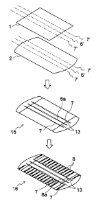
[Second Embodiment]
The manufacturing method of a cleaning item according to a second
embodiment of the present invention is shown in Fig. 6 to Fig. 8. Fig. 6 is an
exploded perspective diagram showing an insertion part formation process; Fig.
7 is an exploded perspective diagram showing a brush formation process; and
Fig. 8 is an exploded perspective diagram showing a joining process.
According to this embodiment, the process differs from the first
embodiment in that only insertion space 33 is formed in the insertion part
formation process, strip part is not formed on the insertion part 36, and on
the
other hand, a strip sheet having a strip part is provided at the uppermost
section
of the brush part 37.
The cleaning item comprises a brush part wherein tow fiber bundle and
strip sheet on which plural slits are formed from the outer boarder of a sheet
formed from fibrous material are layered and the area in the vicinity of the
center line of the layered body is integrated by a plurality of heat-sealing
lines
and an insertion part wherein an insertion space for insertion enabling the
attachment and removal of a gripper are formed by heat-sealing a pair of
sheets.
The insertion part is located on the strip sheet and the strip sheet of the
brush
part and the insertion part are joined by adhesive.
In the insertion part formation process, as shown in Fig. 6, insertion part
36 which has two insertion spaces 33 by layering retention sheet 31 and base
11
CA 02515926 2012-09-21
material sheet 32 and heat-sealing on two lines, joining line 7' and joining
line 6'
which is located roughly in the central part, is formed and the process is
completed.
On the other hand, in the brush part formation process, as shown in Fig.
7, strip sheet 5 on which plural strip pieces are formed, a first a first
fiber bundle
3a made from tow fiber, a second fiber bundle 3b made from tow fiber, a third
fiber bundle 3c made from tow fiber, a fourth fiber bundle 3d made from tow
fiber, and another strip sheet 5 on which plural strip pieces are formed, are
layered in sequential order. Then, the brush part 37 is formed by joining all
six
sheets by heat-sealing on the joining line 6'. In other words, this brush part
37
has strip sheet 5 in the uppermost section and all layers are integrated by
the
brush part sealing line 6b.
Additionally, in the joining process, as shown in Fig. 8, the main
cleaning part 35 is obtained by applying hot-melt 20 to the strip sheet 5 of
the
brush part 37 and joining the brush part 37 and the insertion part 36. By
applying hot-melt 20 onto a strip sheet 5 which is smoother than tow fiber in
this
way, brush part 37 and insertion part 36 can be joined more securely.
[Third Embodiment]
The manufacturing method of a cleaning item according to a third
embodiment of the present invention is shown in Fig. 9 and Fig. 10. Fig. 9 is
an exploded perspective view showing an insertion part formation process and
Fig. 10 is an exploded perspective view showing a joining process.
This embodiment differs from the second embodiment in that, as shown
in Fig. 9, in the insertion part formation process, an insertion part 46 which
has
one insertion space 43 is formed, and in the joining process, two insertion
parts
46 are positioned roughly parallel on the brush part 37. The same brush as
that in the second embodiment is used as brush part 37.
12
CA 02515926 2012-09-21
.=
In the insertion part formation process, as shown in Fig. 9, an insertion
part 46 with only one insertion space 43 is formed by layering retention sheet
41
and base material sheet 42 and heat-sealing only on two joining lines 7.
Then, in the joining process, as shown in Fig. 10, the main cleaning part
45 is obtained by applying hot-melt 20 onto the strip sheet 5 of brush part 37
and joining with the brush part 37 while the two insertion parts 46 are
parallel.
The shape and positioning of respective insertion parts 46 can be selected
accordingly, based on the insert part of the gripper. For example, as in Fig.
11, the insertion part 46 can be only one. In addition, plural insertion parts
can
each be the same as in this embodiment, or they can differ. In this way, in
the
present invention, a plurality of insertion parts can be provided according to
the
number or shape of insert parts on the gripper.
The present invention can be used preferably as a cleaning item for
indoor-use which has fibrous material.
While preferred embodiments of the invention have been described and
illustrated above, it should be understood that these are exemplary of the
invention and are not to be considered as limiting. Additions, omissions, ,
substitutions, and other modifications can be made without departing from the
spirit or scope of the present invention. Accordingly, the invention is not to
be
considered as being limited by the foregoing description, and is only limited
by
the scope of the appended claims.
13