Note: Descriptions are shown in the official language in which they were submitted.
CA 02515944 2005-08-11
WO 2004/072555 PCT/EP2004/001300
PA04/02PC
1
Description
Process and circuit arrangement for igniting a gas stream
Technical area
The invention concerns a process for igniting a gas stream and a circuit
arrangement for carrying out this process as can be used for a gas heating
stove
with gas regulator fittings.
Prior art
Facilities for a gas heating stove or the like are available in a large number
of
designs.
And so an ignition device for igniting gases is described in US 5 722 823 A.
The
ignition device has a magnet coil that operates a gas valve, an igniter to
ignite the
gas stream electrically and a remote control that is connected to the magnet
coil
and the igniter via a low-voltage line. The remote control includes an energy
supply and a time switch for timing the provision of low voltage.
This design requires a great deal of energy to ignite the gas stream. So there
is
provision for three relay coils, which means a relatively high power input.
The
solenoid valve is constantly energised during the ignition process, which
results in
a high power consumption. Consequently the only energy supply option is a
mains
supply. Another disadvantage is that faults occuring within the switch can
lead to
safety-related issues.
A valve device for controlling the ignition of a gas burner is familiar from
the GB 2
351 341 A. An operating spindle is moved by hand into the ignition position,
which
opens the ignition locking valve. The operating spindle needs only be held a
short
time in this position as a microswitch is engaged when the operating spindle
is
CA 02515944 2005-08-11
WO 2004/072555 PCT/EP2004/001300
PA04/02PC
2
moved. This causes a voltage to be made available from a power supply to
engage the magnet. Ignition takes place by piezoelectric spark ignition. The
power
supply is switched off when the thermoelectric current provided by a
thermocouple
is sufficient to keep the ignition locking valve in its open position.
Even with this solution use of a power supply is a disadvantage. Additional
effort is
also needed to carry out the piezoelectric spark ignition. Especially where
there is
a fairly large conduction gap between the ignition locking valve and the
burner
aperture there is a further problem insofar as there cannot yet be any
ignitable gas
1o mixture at the burner aperture, as the time between the ignition locking
valve
opening and ignition is relatively short.
Further to this DE 93 07 895 U describes a multi-function valve with
thermoelectric
locking for gas burners on heating devices. This multifunction valve uses a
room's
existing power supply to operate it. To ignite the gas stream a magnetic valve
is
energised via a pushbutton, opening the ignition locking valve. The gas stream
is
ignited at the same time. A thermocouple in the area of the ignited gas flame
is
heated and puts a magnetic insert into an energised condition via the
resultant
thermoelectric current. The magnet holds an anchor firm and so keeps the
ignition
locking valve linked to the anchor in the open position. Now the pushbutton
can be
released and the magnetic valve be de-energised.
Here it is a disadvantage that the pressure valve must be held long enough
until
the thermoelectric current holds the ignition locking valve in the open
position. It is
also a disadvantage that the power consumption is relatively high in view of
the
fact that the magnetic valve must remain energised for this time via the power
supply so that a mains supply is necessary.
Both solutions described in GB 2 351 341 A a in DE 93 07 895 U also have the
3o disadvantage that they cannot be run fully automatically, and manual
operation is
necessary.
CA 02515944 2005-08-11
WO 2004/072555 PCT/EP2004/001300
PA04/02PC
3
Presenting the invention
The invention is based on the problem of developing a process for fully
automatic
ignition of a gas stream and a switch arrangement for carrying out this
process
that has such a low power consumption that it would be possible to employ an
integrated electricity source with an adequate life. The structure should also
be
kept as simple and as inexpensive as possible.
According to the invention the procedural problem is solved by activating a
1o transverter, which generates a higher voltage from direct current provided
by an
electricity source, with which a storage capacitor and an ignition capacitor
to
provide the ignition voltage are loaded. An essentially familiar ignition
locking
magnet is activated by a holding current provided by the electricity source,
while at
the same time an electric circuit that exists between the ignition locking
magnet
and a thermocouple that can be influenced by the gas flame is interrupted via
a
relay. The storage capacitor is now abruptly discharged via a circuit element,
generating a current surge and briefly energising an electromagnet, to open an
essentially familiar ignition locking valve and at the same time applying the
anchor
of the ignition locking magnet. Owing to the ignition locking magnet activated
by
the holding current the anchor is held in this position after application and
a pilot
light to ignite the outflowing gas is generated via an ignition electrode
linked with
the ignition capacitor via an ignition transformer in a familiar fashion.
Subsequently
further ignition procedures are initiated whereby the ignition capacitor is
recharged
and a new pilot light is generated after charging has taken place. After a
prescribed period of time ignition is terminated. The holding current flowing
from
the electricity source to the ignition locking magnet is interrupted and the
circuit
between the ignition locking magnet and the thermocouple is closed via the
relay.
This has found a solution, which remedies the aforementioned disadvantages of
prior art. A brief operation of the electronic control unit facilitates
ignition of the gas
stream. In view of the only pulsed operation of the electromagnet, which is
independent of how long the control unit is operated, there is a very low
power
CA 02515944 2011-05-25
75590-15
4
requirement. It also possible to access the electricity source to generate the
pilot
light, so that there is no need for the additional cost of a piezoelectric
ignition device.
It proves to be beneficial if, after the electronic control unit is activated
to ignite the
gas stream, a check takes place to determine whether a gas flame is alight. If
the
information is positive the ignition procedure is aborted, while if it is
negative the
aforementioned steps of the procedure are carried out.
There is also an advantageous embodiment of the process if the existence of a
thermal electromagnetic force is measured, while other ignition procedures are
initiated if there is an absence of thermal electromagnetic force. If however
there is
evidence of thermal electromagnetic force ignition is terminated. As soon as
measurements of thermal electromagnetic force indicate that the electronically
calculated thermoelectric current is sufficient to keep the anchor on the
ignition
locking magnet, the holding current flowing from the electricity source to the
ignition
locking magnet is interrupted and the electric circuit between the ignition
locking
magnet and the thermocouple is again closed via the relay.
It is also feasible for the storage capacitor and the ignition capacitor to be
charged
relatively easily via transverters assigned respectively to them at different
voltages.
There is also a favourable embodiment of the process, if a higher alternating
current
is generated from the direct current supplied from the electricity source,
whereby a
power oscillator is used instead of the transverter and the storage capacitor
is only
switched to a first stage of a multiple cascade when the ignition procedure is
initiated,
whereupon the storage capacitor and the ignition capacitor connected by
electrical
conduction with the second stage of the multiple cascade
CA 02515944 2005-08-11
WO 2004/072555 PCT/EP2004/001300
PA04/02PC
are charged to prescribed higher voltages by means of the higher alternating
current via the cascade circuit. After the prescribed higher direct current
voltages
have been reached the power oscillator is switched off and switched on again
when other ignition procedures are initiated.
5
To reduce power requirements even further, which is particularly important
when
the electricity source is a battery, the dimensions of which can be so small
that it
can be located together with the electronic control unit in the housing of the
receiver portion of a remote control, the holding current supplied by the
electricity
io source to hold the anchor can flow simultaneously through the ignition
locking
magnet and the relay, while at the time that the electric circuit between the
ignition
locking magnet and the thermocouple is closed an additional current is briefly
generated to safely prevent the anchor dropping out when the relay is
rearranged
because of the brief interruption in current when the switching contact of the
relay
is interposed. On the other hand it is also feasible for the voltage of the
holding
current supplied to the ignition locking magnet from the electricity source to
be
transverted to the millivolt range via an additional transverter.
It is also advantageous if the existence of a thermal electromagnetic force is
measured using an analogue amplifier.
The safety of the process, such as when a breakdown occurs, is increased by a
procedural step, which after a defined period of time has elapsed, also
interrupts
the energisation of the ignition locking magnet from the electricity source by
using
one or more independendent safety cutoffs, connected in series and timed.
To keep the time between the first ignition procedure and the following
ignition
procedures as brief as possible, it is desirable to save energy by
disconnecting the
storage capacitor from the cascade before further cyclical charges of the
ignition
capacitor.
CA 02515944 2011-05-25
75590-15
6
According to an aspect of the present invention, there is provided
process for igniting a gas flow with an electronic control unit and a gas
regulating
valve, the gas regulating valve having an ignition burner and an ignition
burner valve,
the ignition burner valve operable between open and closed positions with an
electromagnet and held in the open position with a locking magnet, the process
comprising the steps of: generating a higher voltage from a direct current
supplied
from an electricity source, charging a storage capacitor and an ignition
capacitor with
the higher voltage to provide an ignition voltage, activating the locking
magnet with a
holding current provided by the electricity source, while at the same time
interrupting
an electric circuit between the locking magnet and a thermocouple responsive
to the
gas flame via a relay, discharging the storage capacitor via a circuit element
to
generate a surge of current which briefly energizes the electromagnet to open
the
ignition burner valve which is held open by the activated locking magnet,
generating a
pilot light at the ignition burner by igniting gas flowing through the
ignition burner
valve to the ignition burner via an ignition electrode electrically connected
to the
ignition capacitor, and interrupting the holding current flowing from the
electricity
source to the locking magnet and closing the circuit between the ignition
locking
magnet and the thermocouple via the relay after a defined period of time has
elapsed.
According to another aspect of the present invention, there is provided
circuit arrangement for igniting a gas flow with an electronic control unit
and a gas
regulating valve, the gas regulating valve having an ignition burner and an
ignition
burner valve, the ignition burner valve operable with an electromagnet between
an
open position and a closed position and held in the open position with a
locking
magnet, the circuit arrangement comprising: a power converter connected to an
electricity source, a storage capacitor disposed downstream from the power
converter and electrically connected to the electromagnet to operate the
ignition
burner valve, an ignition capacitor electrically connected to an ignition
electrode, a
relay electrically connecting the locking magnet either to the electricity
source or a
thermocouple, at least one timed safety cutoff disposed between the
electricity
CA 02515944 2011-05-25
75590-15
6a
source and the ignition locking magnet, and a first element electrically
connected to
the electronic control unit for measuring the voltage of the thermocouple.
Embodiment
The procedure that is the subject of the invention and circuit arrangement in
accordance with the invention to ignite a gas stream is explained in further
detail in
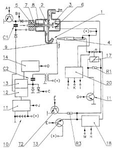
an embodiment below. The individual representations show:
Fig. 1 a schematic representation of the circuit arrangement,
Fig. 2 a detailed representation of the power oscillator
Fig. 3 a detailed representation of the analogue amplifier.
The circuit arrangement in accordance with the invention and exemplified in
Fig. 1 to
carry out the process of igniting a gas stream is employed on a gas regulating
valve.
This gas regulating valve is a switching and regulatory device that is
preferably
intended for installation in a gas-heated chimney stove or similar. It
facilitates the
operation and monitoring of a burner where the gas volume flowing to the
burner is
controlled. As well as assemblies that are not material to the invention and
not
therefore represented in this embodiment, the gas regulating valve also has an
ignition burner 1 and a ignition locking valve 2. The design and function of
the
ignition burner 1 and the ignition locking valve 2 are familiar to specialists
and have
not therefore been explained in detail.
It is triggered by an undescribed microcomputer module serving as an
electronic
control unit, which in this embodiment is located in a likewise undescribed
separately
located housing of the receiver section of a remote control together with an
electricity
source 10. The electricity source 10 consists of standard commercial batteries
as
shown in the drawing, in this case size R6.
CA 02515944 2005-08-11
WO 2004/072555 PCT/EP2004/001300
PA04/02PC
7
A power oscillator 11 detailed further below that can be triggered from the
microcomputer module via a port J, is connected with the electricity source
10.
In series with this is a cascade circuit 12/13 which serves to trigger and
supply
a downstream storage capacitor C1 and to trigger and supply a downstream
ignition capacitor C2. As the voltage required to charge the storage capacitor
C1 is significantly less than the voltage required to charge the ignition
capacitor
C2, the cascade circuit 12/13 is designed as a multiple cascade circuit.
Here the first stage of cascade 12 serves to trigger and supply the downstream
storage capacitor C1. Downstream from this in turn is an electromagnet 5,
which, as shown schematically in the drawing, serves to actuate an essentially
familiar ignition locking valve 2. In view of the brevity of the charge a low
thermal capacity so-called pulse magnet 5 is sufficient.
The second stage of the cascade 13 serves to trigger and supply the
downstream ignition capacitor C2, which is part of an essentially familiar and
therefore not further detailed ignition device. The ignition capacitor C2 can
be
triggered to ignite by the microcomputer module via port C. The second stage
of cascade 13 is connected with an element 14 to monitor the voltage. At the
same time element 14 serves to limit the maximum voltage that can occur, to
prevent a destruction of components. An additional voltage voltage monitor for
the storage capacitor C1 can be omitted, as after the ignition capacitor C2
has
been charged it can be assumed that the storage capacitor C1 has also been
charged. Port D serves to send a check-back signal to the microcomputer
module.
Fig. 2 shows in detail the circuit for the power oscillator 11 being used.
Power
oscillator 11 consists of the CMOS electric circuit 15, essentially familiar
to
specialists, with at least four gates. These gates can be NOR gates, NAND
gates, simple negators etc. Downstream from them is a complementary field
effect power stage 16, to which an LC series oscillator circuit, consisting of
coil
CA 02515944 2005-08-11
WO 2004/072555 PCT/EP2004/001300
PA04/02PC
8
L1 and HF condensor C3 is connected. An RC link serves as a so-called phase
shifter 19 for feedback and phase adjustment.
As further indicated in Fig. 1, a ignition locking magnet 6 forming part of
the
ignition locking valve 2 is linked with a thermocouple 4. The normally closed
contact of a monostable relay 17 is also located in this circuit, whereas this
circuit is open in the energised state and the ignition locking magnet 6
receives
current from the electricity source 10 supplied by the batteries. In addition
to
this a circuit element, in this case a transistor T1, which can be triggered
by the
microcomputer module via port G, is connected on the one hand with the
electricity source 10 and on the other with the relay 17. A resistor R1 is
also
located in parallel with relay 17, as the holding current required for the
ignition
locking magnet 6 is higher than the current flowing through the relay 17. This
circuit also has two series-connected and timed safety cutoffs 18, which are
connected for control purposes with the microcomputer module via the ports H
and M.
Two further circuit elements, a transistor T2 and a transistor T3, are tied up
to
this circuit between relay 17 and safety cutoffs 18. While the transistor T2,
upstream of which there is a resistor R3, is connected with the negative
terminal of electricity source 10 and can be triggered by the microcomputer
module via the port F, transistor T3 is connected with the positive terminal
of
electricity source 10 and can be triggered by the microcomputer module via the
port E.
In addition to this an analogue amplifier 20 is connected in parallel with the
thermocouple 4. This analogue amplifier 20 has the task of measuring a direct
current at thermocouple 4 occurring in the millivolt range, amplifying it and
converting it into a range that the microcomputer module can process. As the
DC amplifiers otherwise customary for such instances on the one hand require
an auxiliary supply above the operating voltage and on the other hand suffer
CA 02515944 2005-08-11
WO 2004/072555 PCT/EP2004/001300
PA04/02PC
9
drift deviations, due to temperature influences for example, the analogue
amplifier 20 is designed as an AC amplifier.
The analogue amplifier, as also described in Fig. 3, is described as follows:
A field effect transistor T4 that can be triggered by the microcomputer module
via port L and a resistor R2 form a controllable voltage divider. A pre-
amplifier
and a booster amplifier are downstream from the voltage divider, with blocking
capacitors C4 / C5 assigned to each of them.
With the pre-amplifier V1 the reference potential is formed by the positive
voltage in order to eliminate fluctuations in the on-board voltage. On the
other
hand, in the case of the booster amplifier V2 the reference potential is
formed
by mass. Both amplifiers V1 / V2 and a trigger TR are operated by the
is microcomputer module through the port K, as they are rendered inoperable
when not required to save electricity. The trigger TR behind the booster
amplifier V2 is linked for its part with the microcomputer module via port I.
To carry out this process the ignition command is passed on to the
microcomputer module via the remote control. The analogue amplifier 20
activated via port K checks whether a thermal electromagnetic force bears
against thermocouple 4 and the relevant information is given to the
microcomputer module via port I. Whereas the ignition procedure is aborted, if
there is an existing thermal electromagnetic force, which is equivalent to a
burning pilot light, if there is no thermal electromagnetic force the voltage
divider of analogue amplifier 20 is triggered by the microcomputer module via
port L. A single switching of the voltage divider will convert the direct
current at
thermocouple 4 at this time into a pulse of alternating current. The pulse
reaches pre-amplifier V1 via the blocking capacitor C4. The signal from the
pre-
amplifier V1 is connected to the booster amplifier V2 via the blocking
capacitor
C5 and further amplified. This analogue signal coming from the booster
CA 02515944 2005-08-11
WO 2004/072555 PCT/EP2004/001300
PA04/02PC
amplifier V2 is digitalised by the trigger TR at fixed trigger points, as
shown in
the diagram associated with Fig. 3.
The diagram plots the course of voltage U during the time t. In a prescribed
5 voltage level SE and on introduction of the pulse signal IS at time TL the
trigger
TR sets an initial trigger point TR1 and at the release of the voltage of
pulse
signal IS a second trigger point TR2, to which a time TE is assigned. The time
lapse between the two points in time TL and TE is a measuring signal MS.
10 The measuring signal MS obtained from the existing thermal electromagnetic
force reaches the microcomputer module via port 1. The length of measuring
signal MS is directly proportional to the thermal electromagnetic force at
thermocouple 4.
Whereas the ignition procedure is aborted if there is any thermal
electromagnetic force, i.e. if the pilot light is already burning, if, on the
other
hand, there is no thermal electromagnetic force the power oscillator 11 will
be
activated by the microcomputer module via port J and the storage capacitor C1
will be switched to the first stage 12 of the multiple cascade via port A.
Activating the power oscillator 11 starts to oscillate the resonant circuit
over the
feedback element i.e. the resonant circuit becomes a self-oscillatory and
frequency-determining power oscillator 11. This means that at the output from
the power oscillator 11 there is a many times higher alternating current
opposed
to the low direct current supplied by the batteries at the input. This
alternating
current charges the storage capacitor C1 and the ignition capacitor C2 with
the
assistance of the two cascade stages 12 / 13, until element 14, which serves
to
monitor the voltage and limit the maximum voltage that occurs, responds and
sends a signal via port D to the microcomputer module, which then switches off
the power oscillator 11 via the port J.
CA 02515944 2005-08-11
WO 2004/072555 PCT/EP2004/001300
PA04/02PC
11
Then the timed safety cutoffs 18 are activated via the port M and the ignition
locking magnet 6 is supplied with a holding current from electricity source 10
via
transistor T1 triggered via port G, energising relay 17, and so opening the
circuit
between ignition locking magnet 6 and thermocouple 4. The resonant circuit C1
is abruptly discharged by the subsequent triggering of port B. Thereupon
resonant circuit C1 is separated from cascade stage 12 via port A. The pulse
magnet 5 is briefly energised by this power surge and a tappet 7 is moved far
enough against the force of a recoil spring 8 for the anchor 3 to attach to
ignition locking magnet 6. Because of the flowing holding current the anchor 3
io is held in this position and the ignition locking valve 2 in the open
position. The
gas can flow through the gas regulating valve to the ignition burner 1.
If a breakdown occurs as a result of a component failure or the like, after a
defined period of time has elapsed the energisation of the ignition locking
magnet 6 via electricity source 10 will also be interrupted by one or more
independent safety cutoffs 18 connected in series and timed and the ignition
locking valve will not remain in the open position, but will be closed again
by
recoil spring 8.
The microcomputer module activates the ignition device via port C, the
ignition
capacitor C2 discharges and the pilot light at ignition electrode 9 flashes
over,
igniting the outflowing gas. After a prescribed period of time has elapsed, in
this
example approx. 1 second, the analogue amplifier 20 is activated via the ports
K and L and a check is carried out to determine whether, because heating has
commenced as a result of the burning pilot light, a detectable voltage is
already
being applied on thermocouple 4, i.e. at least approx. 1 mV.
If this is not the case, further ignition procedures will be introduced,
while, as
already explained in detail above, the power oscillator 11 will be activated,
the
ignition capacitor C2 will be charged and then discharged again when a new
pilot light is generated. With these following ignition procedures the storage
capacitor C1 is separated from cascade stage 12 to save power, as a further
CA 02515944 2005-08-11
WO 2004/072555 PCT/EP2004/001300
PA04/02PC
12
charging of the storage capacitor C1 is no longer necessary. Should no
ignition
of the gas occur within a specified period, the microcomputer module will
abort
the ignition procedure.
Should the minimum voltage exist no further ignition procedures will of course
be initiated, but the available open circuit voltage of thermocouple 4 will
again
be checked until the amount of the current electronically calculated from this
will
be sufficient as holding current for ignition locking magnet 6. At this point
the
analogue amplifier 20 is deactivated via port K and the current flowing from
the
electricity source 10 to the ignition locking magnet 6 is interrupted via port
G.
The relay 17 is de-energised and the make-and-break contacts of relay 17
close the circuit between thermocouple 4 and ignition locking magnet 6. The
anchor 3 is now held by the thermoelectric current.
is To prevent anchor 3 dropping out because of the essentially brief
interruption of
the holding current when the make-and-break contacts of relay 17 are switched
over, the transistor T2 is briefly activated via port F at the time of the
switch-
over and an additional current is generated with similar brevity via the
resistor
R3, safely preventing the anchor dropping off as mentioned above.
Should the gas regulating valve be switched off the switch-off command is
passed on to the microcomputer module via the remote control. By briefly
activating port G and port E while circumventing the safety cutoffs 18 and the
ignition locking magnet 6 a power surge is sent through relay 17, whose make-
and-break contacts briefly lift off as a result. This interrupts the holding
current
flowing between thermocouple 4 and ignition locking magnet 6. The anchor is
no longer held by the ignition locking magnet 6 and the ignition locking valve
2
closes under the influence of the recoil spring 8. The gas flow to ignition
burner
1 and of course to the main burner - not shown - is interrupted and the gas
flame is extinguished.
CA 02515944 2005-08-11
WO 2004/072555 PCT/EP2004/001300
PA04/02PC
13
The process that is the subject of the invention and the circuit arrangement
for
carrying out this process are not of course limited to the embodiment
described.
Alterations, adaptations and combinations are possible without departing from
the
scope of the invention.
It is evident that the transmission of control signals can, as is generally
known, be
made by cable, infra-red, radio waves, ultra-sound etc. It is also possible
for there
no remote control to be used and for all the necessary components to be on or
in
the gas regulating valve. It is also possible for there to be just a main
burner,
io which is ignited directly. Also a small plug-in power supply unit can be
used as an
electricity source (10) instead of batteries, which is then easy to plug in.
CA 02515944 2005-08-11
WO 2004/072555 PCT/EP2004/001300
PA04/02PC
14
List of reference marks
1 ignition burner A to M ports
2 ignition locking valve C1 storage capacitor
3 anchor C2 ignition capacitor
4 thermocouple C3 HF - capacitor
pulse magnet C4 blocking capacitor
6 ignition locking magnet C5 blocking capacitor
7 tappet IS pulse signal
8 recoil spring L1 coil
9 ignition electrode LS pulse signal
electricity source MS measuring signal
11 power oscillator R1 resistor
12 cascade stage 1 R2 resistor
13 cascade stage 2 R3 resistor
14 Element for monitoring SE voltage level
and limiting TE time at TR2
zung TL time at TR1
CMOS circuit TR trigger
16 complementary - field TR1 trigger point
effect
power stage TR2 trigger point
17 relay T1 transistor
18 safety cutoff T2 transistor
19 phase shifter T3 transistor
analogue amplifier T4 field effect transistor
V1 pre-amplifier
V2 booster amplifier
MS measuring signal