Note: Descriptions are shown in the official language in which they were submitted.
CA 02515955 2005-08-12
WO 2004/072843 PCT/NZ2004/000029
"TOUCH SCREEN SIGNAL PROCESSING"
TECHINICAL FIELD
The present invention relates to a touch sensitive screen and in particular to
optically detecting the presence of an object by using signal processing.
BACKGROUND PRIOR ART
Touch screens of the prior art can take on five main forms. These five forms
of
touch screen input device include resistive, capacitive, surface acoustic wave
(SAC,
infrared (IR), and optical. Each of these types of touch screen has its own
features,
advantages and disadvantages.
Resistive is the most common type of touch screen technology. It is a low-cost
solution found in many touch screen applications, including hand-held
computers, PDA's,
consumer electronics, and point-of sale-applications. A resistive touch screen
uses a
controller and a specifically coated glass overlay on the display face to
produce the touch
connection. The primary types of resistive overlays are 4-wire, 5-wire, and 8
wires. The
5-wire and 8-wire technologies are more expensive to manufacture and
calibrate, while 4-
wire provides lower image clarity. Two options are generally given: polished
or anti-
glare. Polished offers clarity of image, but generally introduces glare. Anti-
glare will
minimize glare, but will also further diffuse the light thereby reducing the
clarity. One
benefit of using a resistive display is that it can be accessed with a finger
(gloved or not),
pen, stylus, or a hard object. However, resistive displays are less effective
in public
environments due to the degradation in image clarity caused by the layers of
resistive
film, and its susceptibility to scratching. Despite the trade-offs, the
resistive screen is the
most popular technology because of its relatively low price (at smaller screen
sizes), and
ability to use a range of input means (fingers, gloves, hard and soft stylus).
Capacitive touch screens are all glass and designed for use in ATM's and
similar
kiosk type applications. A small current of electricity runs across the screen
with circuits
located at the corners of the screen to measure the capacitance of a person
touching the
overlay. Touching the screen interrupts the current and activates the software
operating
the kiosk. Because the glass and bezel that mounts it to the monitor can be
sealed, the
CA 02515955 2005-08-12
WO 2004/072843 PCT/NZ2004/000029
-2-
touch screen is both durable and resistant to water, dirt and dust. This makes
it commonly
used in harsher environments like gaming, vending retail displays, public
kiosks and
industrial applications. However, the capacitive touch screen is only
activated by the
touch of a human finger and a gloved finger, pen, stylus or hard obj ect will
not work.
Hence, it is inappropriate for use in many applications, including medical and
food
preparation.
Surface acoustic wave (SAW) technology provides better image clarity because
it
uses pure glass construction. A SAW touch screen uses a glass display overlay.
Sound
waves are transmitted across the surface of the display. Each wave is spread
across the
screen by bouncing off reflector arrays along the edges of the overlay. Two
receivers
detect the waves. When the user touches the glass surface, the user's finger
absorbs some
of the energy of the acoustic wave and the controller circuitry measures the
touch
location. SAW touch screen technology is used in ATM's, Amusements Parks,
Banking
and Financial Applications and kiosks. The technology is not able to be gasket
sealed,
and hence is not suitable to many industrial or commercial applications.
Compared to
resistive and capacitive technologies, it provides superior image clarity,
resolution, and
higher light transmission.
Infrared technology relies on the interruption of an infrared light grid in
front of
the display screen. The touch frame or opto-matrix frame contains a row of
infrared
LEDs and photo transistors; each mounted on two opposite sides to create a
grid of
invisible infrared light. The frame assembly is comprised of printed wiring
boards on
which the opto-electronics are mounted and is concealed behind an infrared-
transparent
bezel. The bezel shields the opto-electronics from the operating environment
while
allowing the infrared beams to pass through. The infrared controller
sequentially pulses
the LEDs to create a grid of infrared light beams. When a stylus, such as a
finger, enters
the grid, it obstructs the beams. One or more phototransistors detect the
absence of light
and transmit a signal that identifies the x and y coordinates. Infrared touch
screens are
often used in manufacturing and medical applications because they can be
completely
sealed and operated using any number of hard or soft objects. The major issue
with
CA 02515955 2005-08-12
WO 2004/072843 PCT/NZ2004/000029
-3-
infrared is the "seating" of the touch frame is slightly above the screen.
Consequently, it
is susceptible to "early activation" before the finger or stylus has actually
touched the
screen. The cost to manufacture the infrared bezel is also quite high.
Optical imaging for touch screens uses a combination of line-scan cameras,
digital
signal processing, front or back illumination and algorithms to determine a
point of touch.
The imaging lenses image the user's finger, stylus or object by scanning along
the surface
of the display. This type of touch screen is susceptible to false readings due
to moving
shadows and bright lights and also requires that the screen be touched before
a reading is
taken. Attempts have been made to overcome these disadvantages. Touch screens
using
optical imaging technology are disclosed in the following publications.
A touch screen using digital ambient light sampling is disclosed in US4943806,
in
particular this patent discloses a touch input device that continuously
samples and stores
ambient light readings and compares these with previously taken readings. This
is done
to minimise the effect of bright light and shadows.
A touch screen for use with a computer system is disclosed in US5914709. In
particular a user input device sensitive to touch is disclosed that uses
threshold adjustment
processing. A light intensity value is read and an "ON" threshold is
established, this
threshold measurement and adjustment is frequently and periodically performed.
This US Patent Number 5317140 patent discloses a method for optically
determining the position and direction of an object on a touch screen display.
In
particular, a diffuser is positioned over the light sources to produce an
average light
intensity over the touch screen.
US Patent Number 5698845 discloses a touch screen display that uses an optical
detection apparatus to modulate the ON/OFF frequency of light emitters at a
frequency of
twice the commercial AC line source. The receiver determines the presence of
light and
compares this to the actual signal transmitted.
US Patent Number 4782328 discloses a touch screen that uses a photosensor unit
positioned at a predetermined height above the touch screen, and when a
pointer nears the
touch screen, rays of its reflected or shadowed ambient light allow it to be
sensed.
CA 02515955 2005-08-12
WO 2004/072843 PCT/NZ2004/000029
-4-
US Patent Number 4868551 discloses a touch screen that can detect a pointer
near
the surface of the display by detecting light reflected by the pointer
(reflected or
diffusive).
DISCLOSURE OF THE INVENTION
It is an obj ect of the present invention to provide a touch sensitive screen
which goes
someway to overcoming the above mentioned disadvantages or which will at least
provide the public with a useful choice.
Accordingly in a first aspect the invention may broadly be said to consist in
a touch
display comprising:
a screen for a user to touch and view an image on or through;
light sources at one or more edges of said screen, said light sources
directing light
across the surface of said screen;
at least two cameras having outputs, each said camera located at the periphery
of
said screen to image the space in front of said screen, said output including
a scanned
image;
means for processing said outputs to detect the level of light, said light
including:
direct light from said light sources, and/or
reflected light from said light sources;
a processor receiving the processed outputs of said cameras, said processor
employing triangulation techniques and said processed outputs to determine
whether the
processed outputs indicate the presence of an object proximate to said screen
and if so the
location of said object.
Preferably said processed output indicates the relative bearing of a presumed
object location relative to said camera.
Preferably said processed output indicates the relative bearing of a presumed
object location relative to the centre of the lens of said camera.
Preferably said processor determines location of said object as a planar
screen co-
ordinate.
CA 02515955 2005-08-12
WO 2004/072843 PCT/NZ2004/000029
-5-
Preferably said light sources are behind said screen arranged to proj ect
light
through said screen and said display includes at each edge having a light
source, light
deflectors in front of said screen, directing light emitted from said light
sources across the
surface of said screen.
Preferably said cameras are line scan cameras, said camera output including
information on line scanned and said processor using said information in
determining
location of said object.
Preferably said touch display including:
means for modulating said light from said light sources to provide a frequency
band within the imageable range of said cameras;
means for excluding image data outside said frequency band.
Preferably said means for processing said outputs includes said means for
excluding image data outside said frequency band and said means for excluding
image
data outside said frequency includes filtering.
Preferably said filtering includes applying a filter selected from the group
consisting of:
a comb filter;
a high pass filter;
a notch filter; and
a band pass filter.
Preferably said touch display including
means for controlling said light sources; and
means for taking and processing an image taken in a non lighted ambient light
state
and in a lighted state;
wherein said means for processing said outputs subtracts the ambient state
from the
lighted state before detecting the level of light.
Preferably said said light sources are LEDs and said touch display includes
means
for controlling the operation of sections of said light source independent of
other sections
of said light source.
CA 02515955 2005-08-12
WO 2004/072843 PCT/NZ2004/000029
-6-
Preferably means for controlling the operation of sections of said light
source
includes means for independently controlling the effective intensity of said
light source.
Preferably said means for controlling sections of said light source comprises
wiring said sections in antiphase and driving using a bridge drive.
Preferably means for controlling sections of said light source comprises using
a
diagonal bridge drive.
Preferably said means for controlling sections of said light source comprises
using
a shift register for each section to be controlled.
Preferably said means for taking and processing images includes controlling
sections of said light sources and each said camera and said means for
processing said
outputs includes processing information on whether a said section is lighted
or not.
Preferably some section are lighted and others are not when an image is taken.
Accordingly in a second aspect the invention may broadly be said to consist in
a
touch display comprising:
a screen for a user to touch and view an image on or through;
light sources at one or more edges edge of said screen, said light sources
directing
light across the surface of said screen;
at least two cameras having outputs located at the periphery of said screen,
said
cameras located so as not to receive direct light from said light sources,
each said camera
imaging the space in front of said screen, said output including a scanned
image;
means for processing said outputs to detect level of reflected light; and
a processor receiving the processed outputs of said cameras, said processor
employing triangulation techniques and said processed outputs to determine
whether the
processed outputs indicate the presence of an object proximate to said screen
and if so the
location of said object.
Preferably said processed output indicates the relative bearing of a presumed
obj ect location relative to said camera.
Preferably said processed output indicates the relative bearing of a presumed
object location relative to the centre of the lens of said camera.
CA 02515955 2005-08-12
WO 2004/072843 PCT/NZ2004/000029
Preferably said processor determines location of said object as a planar
screen co-
ordinate.
Preferably said touch display including:
means for modulating said light from said light sources to provide a frequency
band within the imageable range of said cameras;
means for excluding image data outside said frequency band.
Preferably said means for processing said outputs includes said means for
excluding image data outside said frequency band and said means for excluding
image
data outside said frequency includes filtering.
Preferably filtering includes applying a filter selected from the group
consisting of
a comb filter;
a high pass filter;
a notch filter; and
a band pass filter.
Preferably said touch display including:
means for controlling said light sources; and
means for taking and processing an image taken in a non lighted ambient light
state
and in a lighted state;
wherein said means for processing said outputs subtracts the ambient state
from the
lighted state before detecting the level of light.
Preferably said light sources are LEI~s and said touch display includes means
for
controlling the operation of sections of said light source independent of
other sections of
said light source.
Preferably means for controlling the operation of sections of said light
source
includes means for independently controlling the effective intensity of said
light source.
Preferably the means for controlling sections of said light source comprises
wiring
said sections in antiphase and driving using a bridge drive.
Preferably the means for controlling sections of said light source comprises
using a
diagonal bridge drive.
CA 02515955 2005-08-12
WO 2004/072843 PCT/NZ2004/000029
_g_
Preferably the means for controlling sections of said light source comprises
using a
shift register for each section to be controlled.
Preferably said means for taking and processing images includes controlling
sections of said light sources and each said camera and said means for
processing said
outputs includes processing information on whether a said section is lighted
or not.
Preferably some sections are lighted and others are not when an image is
taken.
Preferably said screen is reflective, said camera further images said screen,
and
said means for processing outputs detects the level of light from the mirror
image.
Preferably said processed out put indicates the relative bearing of a presumed
object relative to said camera and the distance of said object from said
screen.
Accordingly in a third aspect the invention may broadly be said to consist in
a
method of receiving user inputs in reference to an image including the steps
of:
providing a screen for a user to touch and view an image on or through;
providing light sources at one or more edges of said screen, said light
sources
directing light across the surface of said screen;
providing at least two cameras having outputs, each said camera located at the
periphery of said screen to image the space in front of said screen, said
output including a
scanned image;
processing said outputs to detect the level of light, said light including:
direct light from said light sources, and/or
reflected light from said light sources;
processing the processed outputs of said cameras, using triangulation
techniques to
obtain the location of said obj ect.
Preferably said processed output indicates the relative bearing of a presumed
object location relative to a said camera.
Preferably said processed output indicates the relative bearing of a presumed
object location relative to the centre of the lens of said camera.
Preferably said location of is a planar screen co-ordinate.
CA 02515955 2005-08-12
WO 2004/072843 PCT/NZ2004/000029
-9-
Preferably said light sources are behind said screen and arranged to project
light
through said screen and said display includes at each edge having a light
source, light
deflectors in front of said screen, directing light emitted from said light
sources across the
surface of said screen.
Preferably said cameras are line scan cameras, said camera output including
information on line scanned and said processor using said information in
determining
location of said object.
Preferably said method including the steps of
modulating said light from said light sources to provide a frequency band
within
the imageable range of said cameras;
excluding image data outside said frequency band.
Preferably the step of processing said outputs includes the steps of excluding
image data outside said frequency band and said step of excluding image data
outside said
frequency includes filtering.
Preferably filtering includes the step of applying a filter selected from the
group
consisting of:
a comb filter;
a high pass filter;
a notch filter; and
a band pass filter.
Preferably said method including the steps of
controlling said light sources; and
taking and processing an image taken in a non lighted ambient light state and
in a
lighted state;
wherein said step of processing said outputs subtracts the ambient state from
the lighted
state before detecting the level of light.
Preferably said light sources are LEDs and said touch display includes means
for
controlling the operation of sections of said light source independent of
other sections of
said light source.
CA 02515955 2005-08-12
WO 2004/072843 PCT/NZ2004/000029
-10-
Preferably the step of controlling the operation of sections of said light
source
includes independently controlling the effective intensity of said light
source.
Preferably the step of controlling sections of said light source comprises
wiring
said sections in antiphase and driving using a bridge drive.
Preferably the step of controlling sections of said light source comprises
using a
diagonal bridge drive.
Preferably the step of controlling sections of said light source comprises
using a
shift register for each section to be controlled.
Preferably the step of taking and processing images includes controlling
sections
of said light sources and each said camera and said step of processing said
outputs
includes processing information on whether a said section is lighted or not.
Preferably some sections are lighted and others are not when an image is
taken.
Accordingly in a fourth aspect the invention may broadly be said to consist in
a
method of receiving user inputs in reference to an image including the steps
of
providing a screen for a user to touch and view an image on or through;
providing light sources at one or more edges edge of said screen, said light
sources
directing light across the surface of said screen;
providing at least two cameras having outputs located at the periphery of said
screen, said cameras located so as not to receive direct light from said light
sources, each
said camera imaging the space in front of said screen, said output including a
scanned
image;
processing said outputs to detect level of reflected light; and
processing the processed outputs of said cameras, employing triangulation
techniques and said processed outputs to determine whether the processed
outputs
indicate the presence of an object proximate to said screen and if so the
location of said
obj ect.
Preferably said processed output indicates the relative bearing of a presumed
object location relative to said camera.
CA 02515955 2005-08-12
WO 2004/072843 PCT/NZ2004/000029
-11-
Preferably said processed output indicates the relative bearing of a presumed
obj ect location relative to the centre of the lens of said camera.
Preferably said processor determines location of said object as a planar
screen co-
ordinate.
Preferably said method including:
means for modulating said light from said light sources to provide a frequency
band within the imageable range of said cameras;
means for excluding image data outside said frequency band.
Preferably said means for processing said outputs includes said means for
excluding image data outside said frequency band and said means for excluding
image
data outside said frequency includes filtering.
Preferably filtering includes applying a filter selected from the group
consisting of
a comb filter;
a high pass filter;
a notch filter; and
a band pass filter.
Preferably said method including
means for controlling said light sources; and
means for taking and processing an image taken in a non lighted ambient light
state
and in a lighted state;
wherein said means for processing said outputs subtracts the ambient state
from the
lighted state before detecting the level of light.
Preferably said light sources are LEDs and said touch display includes means
for
controlling the operation of sections of said light source independent of
other sections of
said light source.
Preferably the means for controlling the operation of sections of said light
source
includes means for independently controlling the effective intensity of said
light source.
Preferably the means for controlling sections of said light source comprises
wiring
said sections in antiphase and driving using a bridge drive.
CA 02515955 2005-08-12
WO 2004/072843 PCT/NZ2004/000029
-12-
Preferably the means for controlling sections of said light source comprises
using a
diagonal bridge drive.
Preferably the means for controlling sections of said light source comprises
using a
shift register for each section to be controlled.
Preferably said means for taking and processing images includes controlling
sections of said light sources and each said camera and said means for
processing said
outputs includes processing information on whether a said section is lighted
or not.
Preferably some sections are lighted and others are not when an image is
taken.
Preferably said screen is reflective, said camera further images said screen,
and
said means for processing outputs detects the level of light from the mirror
image.
Preferably said processed out put indicates the relative bearing of a presumed
object relative to said camera and the distance of said object from said
screen.
Accordingly in a fifth aspect the invention may broadly be said to consist in
a
method of receiving user inputs in reference to an image:
providing at least one light sources on or adj acent the periphery of said
image, said
light sources directing light across said image;
detecting at at least two locations on or adjacent the periphery of said
image, the
level of light and providing said level as an output;
processing said outputs using triangulation techniques to determine whether
said
outputs indicate the presence of an object proximate to said image and if so
the location of
said object.
Preferably said locations are substantially non-opposite so that when an
object is
present said output is substantially indicative of light reflected from said
object.
Accordingly in a sixth aspect the invention may broadly be said to consist in
a user
input device for locating an object with reference to an image comprising:
at least one light source at or proximate to the periphery of said image, said
light
source directing light across said image;
at one detector having an output, said detector located or in proximity to
said
image to image the space in front of said screen, said output indicative of a
level of light;
CA 02515955 2005-08-12
WO 2004/072843 PCT/NZ2004/000029
-13-
a processor receiving said outputs and using triangulation techniques and said
outputs determining the presence of said obj ect and if so the location of
said obj ect.
BRIEF DESCRIPTION OF THE DRAWINGS
One preferred form of the present invention will now be described with
reference to
the accompanying drawings in which;
Figure 1 is a diagrammatic illustration of a front view of the preferred
embodiment
of the touch screen of the present invention,
Figure la is an illustration of a cross sectional view through X-X of Figure
1,
Figure 1b is an illustration of front illumination of the preferred embodiment
of the
touch screen of the present invention,
Figure 2 is an illustration of the mirroring effect in the preferred
embodiment of the
touch screen of the present invention,
Figure Za is a block diagram of the filter implementation of the preferred
embodiment of the touch screen of the present invention,
Figure 2b is a diagrammatic illustration of the pixels seen by an area camera
and
transmitted to the processing module in the preferred embodiment of the
present
invention,
Figure 3 is a block diagram of the system of the preferred embodiment of the
touch
screen of the present invention,
Figure 4 is a side view of the determination of the position of an obj ect
using the
mirrored signal in the preferred embodiment of the touch screen of the present
invention,
Figure 4a is top view of the determination of the position of an object using
the
mirrored signal in the preferred embodiment of the touch screen of the present
invention,
Figure 5 is an illustration of the calibration in the preferred embodiment of
the touch
screen of the present invention,
Figure 6 is a graph representing in the frequency domain the output from the
imager
in the processing module in the preferred embodiment of the touch screen of
the present
invention,
CA 02515955 2005-08-12
WO 2004/072843 PCT/NZ2004/000029
-14-
Figure 6a is a graph representing in the frequency domain the filters
responses on
the signal from the imager in the preferred embodiment of the touch screen of
the present
invention,
Figure 6b is a graph representing in the frequency domain the separation of
the
object from the background after two types of filtering in the preferred
embodiment of the
touch screen of the present invention,
Figure 7 is an illustration of a front view of the alternate embodiment of the
touch
screen of the present invention,
Figure 7a is an illustration of a cross sectional view through X-X of the
alternate
embodiment of the touch screen of the present invention,
Figure 7b is an illustration of rear illumination of the alternate embodiment
of the
touch screen of the present invention,
Figure 7c is an illustration of rear illumination controlling the sense height
of the
alternate embodiment of the present invention,
Figure 7d is a diagrammatic illustration of the pixels seen by a line scan
camera and
transmitted to the processing module in the alternate embodiment of the
present
invention,
Figure 8 is a graph representing simple separation of an object from the
background
in the alternate embodiment of the present invention,
Figure 9 shows various driving arrangements for sectional backlights of the
present
invention,
Figure 9a shows a two section backlight driven by two wires of the present
invention,
Figure 9b shows a twelve section backlight driven by 4 wires of the present
invention, and
Figure 9c shows a piece of distributed shift register backlight of the present
invention.
CA 02515955 2005-08-12
WO 2004/072843 PCT/NZ2004/000029
-15-
BEST MODE FOR CARRYING OUT THE INVENTION
The present invention relates to improvements in signal processing in the
field of
optical imaging touch screens. In the preferred embodiment the optical touch
screen uses
front illumination and is comprised of a screen, a series of light sources,
and at least two
area scan cameras located in the same plane and at the periphery of the
screen. In another
embodiment, the optical touch screen uses backlight illumination; the screen
is
surrounded by an array of light sources located behind the touch panel which
are
redirected across the surface of the touch panel. At least two line scan
cameras are used
in the same plane as the touch screen panel. The signal processing
improvements created
by these implementations are that an object can be sensed when in close
proximity to the
surface of the touch screen, calibration is simple, and the sensing of an
object is not
effected by the changing ambient light conditions, for example moving lights
or shadows.
A block diagram of a general touch screen system 1 is shown in Figure 3.
Information flows from the cameras 6 to the video processing unit and
computer, together
referred to as the processing module 10. The processing module 10 performs
many types
of calculations including filtering, data sampling, and triangulation and
controls the
modulation of the illumination source 4.
Front Illumination Touch Screen
The preferred embodiment of the touch screen of the present invention is shown
in
Figure 1. The touch screen system 1 is comprised of a monitor 2, a touch
screen panel 3,
at least two lights 4, a processing module (not shown) and at least two area
scan cameras
6. The monitor 2, which displays information to the user, is positioned behind
the touch
screen panel 3. Below the touch screen panel 3 and the monitor 2 are the area
scan
cameras 6 and light sources 4. The light sources 4 are preferably Light
Emitting Diodes
(LED) but may be another type of light source, for example, a fluorescent
tube. LEDs are
ideally used as they may be modulated as required, they do not have an
inherent switching
frequency. The cameras 6 and LEDs 4 are in the same plane as the touch panel
3.
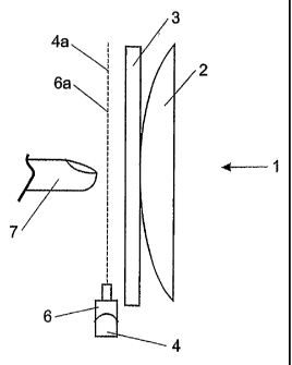
Referring to Figure la, the viewing field 6a of the area scan camera 6 and the
radiation path 4a of the LEDs 4 are in the same plane and parallel to the
touch panel 3.
CA 02515955 2005-08-12
WO 2004/072843 PCT/NZ2004/000029
-16-
When an obj ect 7, shown as a forger, enters into the radiation path 4a, it is
illuminated.
This is typically known as front panel illumination or object illumination. In
Figure 1b,
this principle is again illustrated. Once a finger 7 enters into the radiation
field 4a, a
signal is reflected back to the camera 6. This indicates that a finger 7 is
near to or
touching the touch panel 3. In order to determine if the finger 7 is actually
touching the
touch panel 3, the location of the touch panel 3 must be established. This is
performed
using another signal, a mirrored signal. .
Mirrored Signal
The mirrored signal occurs when the obj ect 7 nears the touch panel 3. The
touch
panel 3 is preferably made from glass which has reflective properties. As
shown in
Figure 2, the finger 7 is positioned at a distance 8 above the touch panel 3
and is mirrored
7a in the touch panel 3. The camera 6 (only shown as the camera lens) images
both the
finger 7 and the reflected image 7a. The image of finger 7 is reflected 7a in
panel 3; this
can be seen through the field lines 6b, 6c and virtual field line 6d. This
allows the camera
6 to image the reflected 7a image of the finger 7. The data produced from the
camera 6
corresponds to the position of the field lines 6e, 6b as they enter the camera
6. This data
is then fed into a processing module 10 for analysis.
A section of the processing module 10 is shown in Figure 2a. Within the
processing
module 10 is a series of scanning imagers 13 and digital filters 11 and
comparators 12
implemented in software. There are a set number of pixels on the touch panel,
for
example 30,000 pixels. These may be divided up into 100 columns of 300 pixels.
The
number of pixels may be more or less than the numbers used, the numbers are
used for
example only. In this situation, there are 30,000 digital filters 11 and
comparators 12,
broken up into 100 columns of 300 pixels, this forms a matrix similar to the
matrix of
pixels on the monitor 2. A representation of this is shown in Figure 2a as one
column is
serviced by one image scanner 13 and three sets 14a, 14b, 14c of digital
filters 11 and
comparators 12, this allows information from three pixels to be read. A more
illustrated
example of this matrix is shown in Figure 2b. Eight pixels 3a-3h are
connected, in groups
of columns, to an image scanner 13 that is subsequently connected to a filter
11 and a
CA 02515955 2005-08-12
WO 2004/072843 PCT/NZ2004/000029
-17-
comparator 12 (as part of the processing module 10). The numbers used in
Figure 2b are
used for illustration only; an accurate number of pixels could be greater or
less in number.
The pixels shown in this diagram may not form this shape in the panel 3, their
shape will
be dictated by the position and type of camera 6 used.
Referring back to Figure 2, finger 7 and mirrored finger 7a activates at least
two
pixels; two pixels are used for simplicity. This is shown by the field lines
6e and 6b
entering the processing module 10. This activates the software so the two
signals pass
through a digital filter 11 and a comparator 12 and results in a digital
signal output 12a-
12e. The comparator 12 compares the output from the filter 11 to a
predetermined
threshold value. If there is a finger 7 detected at the pixel in question, the
output will be
high, otherwise it will be low.
The mirrored signal also provides information about the position of the finger
7 in
relation to the cameras 6. It can determine the height 8 of the finger 7 above
the panel 3
and its angular position. The information gathered from the mirrored signal is
enough to
determine where the finger 7 is in relation to the panel 3 without the forger
7 having to
touch the panel 3.
Figures 4 and 4a show the positional information that is able to be obtained
from the
processing of the mirrored signal. The positional information is given in
polar co-
ordinates. The positional information relates to the height of the anger 7,
and the position
of the finger 7 over the panel 3.
Referring again to Figure 2, the height that the finger 7 is above the panel 3
can be
seen in the distance between the outputs 12a-12e. In this example the finger 7
is a height
8 above the panel 3 and the outputs 12b and 12e are producing a high signal.
The other
outputs 12a, 12d are producing a low signal. It has been found that the
distance 9
between the high outputs 12b, 12e is twice as great as the actual height 8 of
the finger
above the panel 3.
Modulating
The processing module 10 modulates and collimates the LEDs 4 and sets a
sampling
rate. The LEDs 4 are modulated, in the simplest embodiment the LEDs 4 are
switched on
CA 02515955 2005-08-12
WO 2004/072843 PCT/NZ2004/000029
-1~-
and off at a predetermined frequency. Other types of modulation are possible,
for
example modulation with a sine wave. Modulating the LEDs 4 at a high frequency
results
in a frequency reading (when the finger 7 is sensed) that is significantly
greater than any
other frequencies produced by changing lights and shadows. The modulation
frequency
is greater than SOOHz but no more than ~l OkHz.
Sampling
The cameras 6 continuously generate an output, which due to data and time
constraints is periodically sampled by the processing module 10. In the
preferred
embodiment, the sampling rate is at least two times the modulation frequency;
this is used
to avoid aliasing. The modulation of the LEDs and the sampling frequency does
not need
to be synchronised.
Filtering
The output in the frequency domain from the scanning imager 13 is shown in
Figure
6. In Figure 6, there are two typical graphs, one showing when there is no obj
ect being
sensed 21 and one showing when a finger is sensed 20. In both graphs there is
a region of
movement of shadows 22 at approximately 5 to 20Hz, and an AC mains frequency
region
23 at approximately 50 to 60Hz.
In the preferred embodiment when there is not object in the field view, no
signal is
transmitted to the area camera so there are no other peaks in the output. When
an obj ect
is in the field of view, there is a signal 24 corresponding to the LED
modulated frequency,
for example SOOHz. The lower unwanted frequencies 22, 23 can be removed by
various
forms of filters. Types of filters can include comb, high pass, notch, and
band pass filters.
In Figure 6a the output from the image scanner is shown with a couple of
different
filter responses26, 27 being applied to the signal 20. In a simple
implementation a SOOHz
comb filter 26 may be implemented (if using a SOOHz modulation frequency).
This will
remove only the lowest frequencies. A more advanced implementation would
involve
using a band pass 27 or notch filter. In this situation, all the data, except
the region where
the desired frequency is expected, is removed. In Figure 6a this is shown as a
SOOHz
narrow band filter 27 applied to the signal 20 with a modulation frequency of
SOOHz.
CA 02515955 2005-08-12
WO 2004/072843 PCT/NZ2004/000029
-19-
These outputs 30, 31 from the filters 26, 27 are further shown in Figure 6b.
The top graph
shows the output 30 if a comb filter 26 is used while the bottom graph shows
the output
31 when a band filter 27 is used. The band filter 27 removes all unwanted
signals while
leaving the area of interest.
Once the signal has been filtered and the signal in the area of interest
identified, the
resulting signal is passed to the comparators to be converted into a digital
signal and
triangulation is performed to determine the actual position of the object.
Triangulation is
known in the prior art and disclosed in US5534917 and US4782328, and are
herein
incorporated by reference.
Calibration
The preferred embodiment of the touch screen of the present invention uses
very
quick and easy calibration that allows the touch screen to be used in any
situation and
moved to new locations, for example the touch screen is manufactured as a lap
top.
Calibration involves touching the panel 3 in three different locations 31a,
31b, 31c, as
shown in Figure 5; this defines the touch plane of the touch panel 3. These
three touch
points 31 a, 31 b, 31 c provide enough information to the processing module
(not shown) to
calculate the position and size of the touch plane in relation to the touch
panel 3. Each
touch point 31 a, 31 b, 31 c uses both mirrored and direct signals, as
previously described,
to generate the required data. These touch points 31 a, 3 1b, 31 c may vary
around the
panel 3, they need not be the actual locations shown.
Back Illumination Touch Screen
Figure 7 shows the alternate embodiment of the touch screen of the present
invention. As in the preferred embodiment, the monitor 40 is behind the touch
panel 41
and around the sides and the lower edge of the panel 41 is an array of lights
42. These
point outwards towards the user and are redirected across the panel 41 by a
diffusing plate
43. The array of lights 42 consists of numerous Light Emitting Diodes (LEDs).
The
diffusing plates 43 are used redirect and diffuse the light emitted from the
LEDs 42 across
the panel 41. At least two line-scan cameras 44 are placed in the upper two
corners of the
panel 3 and are able to image an object. The cameras 44 can be alternately
placed at any
CA 02515955 2005-08-12
WO 2004/072843 PCT/NZ2004/000029
-20-
position around the periphery of the panel 41. Around the periphery of the
touch panel 41
is a bezel 45 or enclosure. The bezel 45 acts as a frame that stops the light
radiation from
being transmitted to the external environment. The bezel 45 reflects the light
rays into the
cameras 44 so a light signal is always read into the camera 44 when there is
no obj ect near
the touch panel 41.
Alternately, the anay of lights 42 may be replaced with cold cathode tubes.
When
using a cold cathode tube, a diffusing plate 43 is not necessary as the outer
tube of the
cathode tube diffuses the light. The cold cathode tube runs along the entire
length of one
side of the panel 41. This provides a substantially even light intensity
across the surface
of the panel 41. Cold cathode tubes are not preferably used as they are
difficult and
expensive to modify to suit the specific length of each side of the panel 41.
Using LED's
allows greater flexibility in the size and shape of the panel 41.
The diffusing plate 43 is used when the array of lights 42 consists of
numerous
LED's. The plate 43 is used to diffuse the light emitted from an LED and
redirect it
across the surface of panel 41. As shown in Figure 7a, the light 47 from the
LEDs 42
begins its path at right angles to the panel 41. Once it hits the diffusing
plate 43, it is
redirected parallel to the panel 41. The light 47 travels slightly above the
surface of the
panel 41 so to illuminate the panel 41. The light 47 is collimated and
modulated by the
processing module (not shown) as previously described.
Referring to Figure 7a, increasing the width 46 of the bezel 45 can be
increased or
decreased. Increasing the width 46 of the bezel 45 increases the distance at
which an
object can be sensed. Similarly, the opposite applies to decreasing the width
10 of the
bezel 45
The line scan cameras 44 consists of a CCD element, lens and driver control
circuitry. When an image is seen by the cameras 44 a corresponding output
signal is
generated.
Referring to Figures 7b and 7c, when the touch screen is not being used, i.e.
when
there is no user interaction or input, all the light emitted from the array of
lights 42 is
transmitted to the line-scan cameras 44. When there is user input, i.e. a user
selects
CA 02515955 2005-08-12
WO 2004/072843 PCT/NZ2004/000029
-21 -
something on the screen by touching it with their forger; a section of the
light being
transmitted to the camera 44 is interrupted. Through calculations utilising
triangulation
algorithms with the outputted data from the camera 44, the location of the
activation can
be determined.
The line scan cameras 44 can read two light variables, namely direct light
transmitted from the LED's 42 and reflected light. The method of sensing and
reading
direct and mirrored light is similar to what has been previously described,
but is simpler
as line scan cameras can only read one column from the panel at once; it is
not broken up
into a matrix as when using an area scan camera. This is shown in Figure 7d
where the
panel 41 is broken up into sections 14a-14d (what the line scan camera can
see). The rest
of the process has been described previously. The pixels shown in this diagram
may not
form this shape in the panel 41, their shape will be dictated by the position
and type of
camera 44 used.
In the alternate embodiment, since the bezel surrounds the touch panel, the
line scan
cameras will be continuously reading the modulated light transmitted from the
LEDs.
This will result in the modulated frequency being present in the output
whenever there is
no object to interrupt the light path. When an object interrupts the light
path, the
modulated frequency in the output will not be present. This indicates that an
object is in
near to or touching the touch panel. The frequency present in the output
signal is twice
the height (twice the amplitude) than the frequency in the preferred
embodiment. This is
due to both signals (direct and mirrored) being present at once.
In a further alternate embodiment, shown in Figure ~, the output from the
camera is
sampled when the LEDs are modulating on and off. This provides a reading of
ambient
light plus backlight 50 and a reading of ambient light alone 51. When an
object interrupts
the light from the LEDs, there is a dip 52 in the output 50. As ambient light
varies a lot, it
is difficult to see this small dip 52. For this reason, the ambient reading 51
is subtracted
from the ambient and backlight reading 50. This results in an output 54 where
the dip 52
can be seen and thus simple thresholding can be used to identify the dip 52.
CA 02515955 2005-08-12
WO 2004/072843 PCT/NZ2004/000029
-22-
Calibration of this alternate embodiment is performed in the same manner as
previously described but the touch points 31a, 31b, 31c (referring to Figure
5) cannot be
in the same line, they must be spread about the surface of the panel 3.
In figure 7 the backlight is broken up into a number of individual sections,
42a to
42f. One section or a subset of sections is activated at any time. Each of
these sections is
imaged by a subset of the pixels of the image sensors 44. Compared to a system
with a
single backlight control, the backlight emitters are operated at higher
current for shorter
periods. As the average power of the emitter is limited, the peak brightness
is increased.
Increased peak brightness improves the ambient light performance.
The backlight switching may advantageously be arranged such that while one
section is illuminated, the ambient light level of another section is being
measured by the
signal processor. By simultaneously measuring ambient and backlit sections,
speed is
improved over single backlight systems.
The backlight brightness is adaptively adjusted by controlling LED current or
pulse
duration, as each section is activated so as to use the minimum average power
whilst
maintaining a constant signal to noise plus ambient ratio for the pixels that
view that
section.
Control of the plurality of sections with a minimum number of control lines is
achieved in one of several ways.
In a first implementation of a two section backlight the two groups of diodes
44a,
44b can be wired antiphase and driven with bridge drive.
In a second implementation with more than two sections, diagonal bridge drive
is
used. In figure 9b, 4 wires are able to select 1 of 12 sections, 5 wires can
drive 20
sections, and 6 wires drive 30 sections.
In a third implementation 9c, for a large number of sections, a shift register
60 is
physically distributed around the backlight, and only two control lines are
required.
X-Y multiplexing arrangements are well known in the art. For example an 8+4
wires are used to control a 4 digit display with 32 LED's. Fig9b shows a 4
wire
diagonal multiplexing arrangement with 12 LEDs. The control lines A,B,C,D are
driven
CA 02515955 2005-08-12
WO 2004/072843 PCT/NZ2004/000029
-23.-
by tristate outputs such as are commonly found at the pins of microprocessors
such as
the Microchip PIC family. Each tristate output has two electronic switches
which are
commonly mosfets. Either or neither of the switches can be turned on. To
operate led
Lla, switches A1 and BO only are enabled. To operate L1B, AO and B1 are
operated. To
operate L2a, A1 and DO are enabled, and so on. This arrangement can be used
with any
number of control lines, but is particularly advantageous for the cases of
4,5,6 control
lines, where 12,20,30 leds can be controlled whilst the printed circuit board
tracking
remains simple. Where higher control numbers are used it may be advantageous
to use
degenerate forms where some of the possible leds are omitted to ease the
practical
interconnection difficulties.
The diagonal multiplexing system has the following features:
- it is advantageous where there are 4 or more control lines .
- it requires tri-state push-pull drivers on each control line
- rather than using an x-y arrangement of control lines with led's at the
crossings,
the arrangement is represented by a ring of control lines with a pair of
antiphase LED's
arranged on each of the diagonals between the control lines. Each LED can be
uniquely
selected, and certain combinations can also be selected.
- uses the minimum possible number of wires
- where emc filtering is needed on the wires there is a significant saving in
components
To those skilled in the art to which the invention relates, many changes in
construction and widely differing embodiments and applications of the
invention will
suggest themselves without departing from the scope of the invention as
defined in the
appended claims. The disclosures and the descriptions herein are purely
illustrative and
are not intended to be in any sense limiting.