Note: Descriptions are shown in the official language in which they were submitted.
CA 02516111 2005-08-15
1
Method and device for testing coins
The invention relates to a method and a device for
testing coins, in which the image of the coin is
detected using an image sensor.
In the process of recognising the embossing on coins
there is a known way of using photographic image
sensors which usually have pixels arranged in columns
and lines. Here it is necessary to determine the
correct moment of the recording of the moved objects
i.e. the coin (here the term "coin" is used to denote
also tokens or counters or the like). One problem is
detecting the coin in its unrestricted course of
movement and monitoring the run of the coins only with
the image recording system present or the image sensor.
During the dynamic behaviour of a coin as it passes an
image sensor and the production of an image by the
optical image sensor, exact analysis of the times of
CA 02516111 2005-08-15
2
passing through the imaging area and the recording
speed of the sensor must be made. It is crucial to
determine the correct value for the exposure time and
the moment of the recording. Although it is possible
in special cases, it is not to be expected that the
coin will move through the recording area of the image
sensor at a constant speed and certainly will not stay
there for a short time at all. There are four time
areas to be examined, namely the run-in of the coin
into the sensor area, the recording/ exposure time, the
data transfer or transmission for processing the image
in an evaluation device and the image processing,
analysis and evaluation. Whilst for the fourth time
period no fixed time value is given, apart from the
maximum time of the entire process, the first three
time periods are extremely time-critical.
Run-in times for selected coins were determined, the
run-in time being determined as the time from the
appearance of the edge of the coin in the recording
area of the image sensor up to complete detection of
the coin by this recording area. The measured run-in
time was between 4.5 and 9.9 ms and that of 0.01, 0.10,
1 and 2 Euro coins was respectively 4.9, 5.9, 6.99 and
7.71 ms. The aimed-at diameter range of the coins to be
measured is between 15 mm and 33 mm. Measurements in
real coin checkers produced a maximum coin speed of 3
m/s. With the given time conditions it is
inconceivable to follow the run of the coin up to the
correct recording position by cyclical scanning of the
image. Moreover in such a case the data transfer times
from the image sensor to the operating processors is
much too long.
The object underlying the invention is to create a
method and a device for testing coins using an image
sensor to record an image of the coin to be tested, in
which the moment of the recording of the image of the
CA 02516111 2010-01-29
3
coin or respectively the location of the recording is
reliably determined and with which the data transfer times
from the image sensor to the evaluation device are
minimised.
In accordance with an embodiment of the present invention
there is provided a method for testing coins which are
inserted into a coin checker and run past an image sensor
which has lines and columns and which records an image of
the coin to be checked, the method comprising the steps of:
providing at least one front column in a direction of
movement of the coin; detecting parameters of the coin by
the at least one front column; providing information about
the movement of the coin from detected parameters of the
coin and temporal detection information; determining when
the coin will appear in a coverage area of the image sensor
which is desired for recording; switching the image sensor
into activation of the columns and lines of the coverage
area; triggering the recording; scanning a front edge and an
apex of the coin by the at least one front column in the
direction of movement; determining the diameter of the coin
from the scanned apex; and activating at least one line of
the image sensor at a level of half the diameter after
detection of the apex of the coin.
In accordance with a further embodiment, there is provided
a device for testing coins which are inserted into a coin
checker, the device having an image sensor which has lines
and columns for recording an image of the coin to be checked
which passes the image sensor, and an evaluation device
connected to the image sensor, at least one of the front
columns in the direction of movement of the coin is
activated to detect parts of the coin, and the evaluation
CA 02516111 2010-01-29
- 3a -
device determines a desired coverage area from signals of
the image sensor and associated temporal information and
triggers the image sensor to record, wherein the evaluation
device determines an apex and thus a diameter of the coin
from the signals of the at least one front column, and
wherein the lines and columns of the image sensor are
activatable independently of one another or in areas.
The invention exploits the capability of image sensors to
select just partial areas. Since the scanning speed of the
individual pixels is independent of their number, the
transfer speed can be assumed practically proportional to
the number of points to be selected. Because only at least
one front column in the direction of movement of the coin
and/or at least one line of the image sensor detect
parameters of the coin, which together with the temporal
detection information provide information about the movement
of the coin, and because in dependence on these parameters
and the temporal information it is determined when the coin
will appear in a coverage area, desired for recording, of
the image sensor, the image sensor being switched into
activation of the columns and lines of the coverage area and
the recording being triggered, it is possible to monitor the
movement of the coin and to calculate exactly the moment of
the actual recording of the image of the coin, and as a
result of the activation of only the coverage area of the
coin with the image sensor, the time for reading out the
image data is reduced.
Through detection the apex of the coin by the at least one
front column in the direction of movement, the diameter of
the coin can be determined, via which
CA 02516111 2005-08-15
4
information can be provided about the height and width
of the coverage area.
By scanning the front edge and the apex of the coin and
the temporal information of the scanning and the
diameter of the coin, the speed of the coin can be
calculated in a simple manner, and especially in the
case of small coins which run slowly this speed
information is already sufficient to fix the moment of
the recording, since the recording area of the image
sensor is somewhat larger than the coin surface and
thus running out of the sensor area without being
checked is unlikely.
It is especially advantageous, after detection of the
apex of the coin, to activate at least one line of the
image sensor at the level of half the diameter, and to
scan the front edge of the coin a number of times,
since the speed and/or the acceleration of the coin can
be calculated exactly as a function of the scanning
times and the distances covered. Thus the recording
moment can be determined exactly even if the coin
experiences a delay or acceleration in the course of
its run-in.
It is advantageous that as the coin runs through the at
least one column, the height pattern of the coin is
detected and evaluated, grooves being recognised where
discontinuities are present in the height pattern.
An illumination device is advantageously provided which
is activated in a pulsed manner at the moment of the
recording, and thus good illumination can be achieved
as a result of the fixing of the moment of the
recording, it being possible to determine the length of
the illumination as a function of the speed of the
coin.
CA 02516111 2005-08-15
Embodiments of the invention are represented in the
drawings and are explained in greater detail in the
following description. The figures show:
Figs. 1-4 different states of movement of the coin
5 in relation to an image sensor, and
Figs. 5 and 6 a schematic illustration of the scanning
of milled coins.
The device according to the invention is installed in a
coin checker, preferably in the coin channel, in which
the other measuring systems of the coin checker are
also present, and the described device can be
configured as a sub-system of the coin checker control
system. The device has an image sensor, the term
"image sensor" being intended to cover the entire
recording device with lens system. In addition, an
illuminating device is provided which is associated
with the image sensor and which has a flashlight
function, i.e. generates pulsed illumination of the
coin surface.
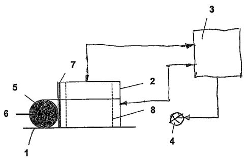
A device according to the invention is represented
schematically in Fig. 1 and has the image sensor 2
arranged in the region of a coin track 1, with an
appropriate lens system as well as an evaluation unit
3, which is a constituent part of the coin checker
control system, and an illumination assembly 4. The
recording device configured as the image sensor 2 is so
set with the lens system that a specific visual field
and a specific focus area are preset, and a coin 5 to
be photographed should be arranged in this area so that
no optical distortions or obscuration occur. The image
sensor 2, the illustration of which shows the coverage
area, is provided with a large number of columns and
lines which are formed from pixels and connected to the
evaluation unit 3 and which may be triggered
CA 02516111 2005-08-15
6
individually or in areas by the evaluation unit 3 for
their initialisation and activation for the process of
reading out the data from the sensor as well as for the
actual recording. The recording is the process of
"electronically fixing" the optical image, i.e. the
optical function as charge carrier is taken over with
an electronic "shutter". This happens in as short a
period of time as possible in order to avoid movement
blurs. As the data are being read out of the sensor,
the coin is already moving forward. With the
triggering of the lines and columns for the recording,
the illumination device 4 is also triggered.
So that an assessable recording of a coin 5 can be
achieved, the moment of the recording, based on the
movement parameters of the incoming coin 5, must be
determined via the evaluation unit 3 at the desired
measuring position or at the desired recording
location. To this end, in the preferred embodiment at
the beginning of the detection only the first column 7
of the image sensor 2 in the direction 6 of movement of
an incoming coin 5 is activated, the pixels of this
first column 7 being continuously read out by the
evaluation unit 3 and the run-in of the coin being
awaited. As the coin 5 enters the image sensor, the
front edge is detected by the column 7 and recognised
by the evaluation unit 3, which activates a height
check which is intended to recognise the apex of the
coin.
On reaching the apex, according to Fig. 2, the
evaluation unit 3 determines the diameter of the coin 5
which is stored as the first measured value of the
system. The desired coverage area is fixed from the
diameter.
At this point in time, a first assessment of the run-in
speed of the coin is possible since a speed can be
CA 02516111 2005-08-15
7
calculated from the moment of scanning the front edge,
the moment of scanning the apex and from the diameter.
In the simplest case, i.e. if certain indistinctness is
admitted, this information is already sufficient to fix
the moment of the recording, which can be calculated
from the speed and the desired measuring position.
This is true in particular for small coins which run
slowly, since the desired recording area 8, represented
in broken lines, in this case covers most of the coin
surface and thus the coin is unlikely to exit from the
sensor area without being checked. If however it is to
be expected that the speed will alter as the coin runs
in, additional checking of the passage of the coin is
necessary.
For this additional checking of the passage of the
coin, reference is made to Fig. 3, in which a pixel
line 9 on the centre line relative to the diameter of
the coin 5 is activated. This activation is undertaken
by triggering the evaluation unit 3 after recognising
the diameter of the coin 5. In this case, the first
scanning line 7 can be deactivated. Scanning the front
edge of the coin 5 on the centre line provides
continuously the progress of the coin as it runs
through the system. With the temporal information of
the scanning of the front edges and the distances
respectively covered, the respective speed and, if
desired, the respective acceleration can be determined,
which then serve to determine the time of the coin's
arrival at the measuring position. As a function of
this temporal prediction and/or once the coin 5 has
completely entered the designated recording area 8, the
lines and columns of. the image sensor are initialised
in the height and width predetermined by the diameter
of the coin 5, as the coverage area at the recording
location, by the evaluation unit 3, and triggered at
the previously calculated point in time. This is shown
in Fig. 4, in which the coin is shown in the desired
CA 02516111 2005-08-15
8
coverage area 10 with the image sensor. Due to the
previously ascertained diameter of the coin and the
time at the measuring position, determined from the
speed or acceleration, the coverage area of the image
sensor 2 which is to be recorded can be selected in an
optimum manner.
Depending on the coin size, the coverage area or
recording area is limited by the evaluation unit 3
triggering the lines and columns, the time for reading
out the image data being reduced to a minimum. If the
evaluation of the data is matched to this, in order to
save space in the working memory, even the areas of the
coverage area 10 which are located outside the circular
image can be suppressed, i.e. the signals from these
areas are not passed on by the evaluation unit 3.
During the recording according to Fig. 4, the
illumination device 4 is simultaneously triggered by
the evaluation unit 3, which also determines the
exposure time from the previous information about the
speed and the diameter. For reproducible illumination,
which is as free of shadows as possible, of the coin
surface during the recording, a diffuse, even and as
bright as possible illumination of the coin is
required. This is activated as already mentioned only
at the moment of the recording and also in a pulsed
manner on account of the high consumption of current.
The illumination for the recording can take the form
for example of a plurality of light diodes arranged in
a ring with a diffuse reflector.
According to present knowledge, the exposure time of
the recording must be controlled with the aid of
deliberate control of the illumination. This is
necessary since circulating coins have a very strong
spectrum of contamination and oxidation and thus
CA 02516111 2005-08-15
9
reflection capability. Furthermore, for cost reasons,
a lens system with a fixed aperture is usually used.
On account of the expected high running speed of the
coin, controlling exposure by the exposure time has to
be excluded if possible. The exposure must be kept as
short as possible in order to avoid movement blurs.
There remains the possibility of controlling the
current supply to the illumination elements or to a
gain control of the image sensor.
In addition to the illumination for the actual
recording, illumination for checking the coin run-in is
required, which can be configured as point-source or
linear illumination with a lower light intensity or
energy than the main illumination in that area.
Independently of the demands on the illumination for
recording the coin, therefore other illumination
techniques can be used in the run-in area, by means of
which additional measured values can be obtained, e.g.
flat directional, in order to ascertain embossing
depths with shadow formation, multi-coloured
illumination for recognising two-coloured coins,
coloured illumination for recognising the material.
It must also be considered that the illumination for
the run-in check has to be activated a number of times
if not even constantly over the entire period of the
coin run-in.
Naturally this illumination for the run-in check is
controlled by the evaluation unit 3, which basically
monitors the run-in. Here it can also determine the
average brightness of the coin which is used for
controlling the exposure.
CA 02516111 2005-08-15
In certain circumstances, the method can be simplified
to remove the recording time by additional checking of
the passage of the coin as per Fig. 3 being dispensed
with. Then monitoring only via the first column is
5 achieved, the moment of the passage of the first edge
and the moment of the passage of the apex, which
however cannot be fixed exactly because of the
tangential run-in, being determined. The moment of the
passage of the rear edge can possibly also be detected.
10 As above, the speed can be determined by using the
diameter and the recording moment can be predicted from
the speed, and in addition the moment of the passage of
the rear edge can be used for checking. The simplified
scanning is reliable if the boundary conditions are not
so time-critical and the coin movements are continuous
enough for exact checking of the coin's running not to
be necessary.
As a support to the run-in check in the first column, a
column within the scanning area 8 can also be scanned.
The time of reaching this position can then be used
together with the spacing of the columns in determining
the speed.
In certain cases, especially when the diameter ranges
of the coins to be detected are similar, monitoring
only via one line can be envisaged. But with this
monitoring there is the problem of fixing the correct
position of the line to be scanned. Therefore a
compromise has to be made in respect of precision.
Otherwise in this method also the front edge and the
rear edge of the coin are detected, it being possible
to determine the central position of the coin with this
information. In this type of scanning, a larger
scanning area of the image sensor is necessary.
There also exist image sensors which do not admit any
freely positionable selection of image data, but which
CA 02516111 2005-08-15
11
make possible reading of pixels in blocks or switching
down to a much smaller resolution. In these cases too,
the previously mentioned scanning by means of columns
and possibly lines can be carried out, the columns and
lines then having a reduced number of pixels.
In Fig. 5 and Fig. 6 is represented a so-called groove
check, which can be carried out with the preferred
embodiment. The entry of the coin into the image
sensor or the measuring system is monitored by the
rapid scanning of the first column, and the apex of the
coin, i.e. its diameter, as mentioned, is determined.
When the height pattern is checked, discontinuities can
be evaluated as grooves. With the appropriate
mathematical correlation, the recognition of polygonal
coins is also possible.
As shown in Fig. 5, an enlargement of the upper coin
edge 11 as it runs through the first column 7 of the
image sensor 2 is illustrated. In the simplest case,
only one column is scanned and the repeated change of
the uppermost pixel as the apex runs through is
recognised as milling. Knowing the speed of the coin,
the width of the grooves can also be deduced.
An expanded form having two adjacent columns 7, 12
simplifies the recognition of a groove since then two
adjacent pixels respectively supply two negated
signals. Their change shows the presence of milling on
the edge of the coin 11. For the sake of simplicity,
in Fig. 6 the starting point is a groove depth of the
dimensions of one pixel of the image sensor. Depending
on the resolution of the image sensor, however, the
groove depth can also be a plurality of pixels. Then
the groove depth becomes a measurable feature of the
coin.