Language selection

Search

Patent 2516201 Summary

Third-party information liability

Some of the information on this Web page has been provided by external sources. The Government of Canada is not responsible for the accuracy, reliability or currency of the information supplied by external sources. Users wishing to rely upon this information should consult directly with the source of the information. Content provided by external sources is not subject to official languages, privacy and accessibility requirements.

Claims and Abstract availability

Any discrepancies in the text and image of the Claims and Abstract are due to differing posting times. Text of the Claims and Abstract are posted:

  • At the time the application is open to public inspection;
  • At the time of issue of the patent (grant).
(12) Patent Application: (11) CA 2516201
(54) English Title: APPARATUS FOR SANITIZING BOTTLES AND DIPENSING PURIFIED WATER INTO THE BOTTLES
(54) French Title: DISPOSITIF DE DESINFECTION DE BOUTEILLES ET DE DISTRIBUTION D'EAU PURIFIEE DANS LES BOUTEILLES
Status: Deemed Abandoned and Beyond the Period of Reinstatement - Pending Response to Notice of Disregarded Communication
Bibliographic Data
Abstracts

English Abstract


A stand for dispensing purified water into a supply bottle has both a
dispensing nozzle on the stand with a customer actuated switch supply of the
water
through the spout and a sanitizing system in the stand for pre-sanitizing the
bottle
prior to filling at the point. The sanitizing system includes a nozzle for
injecting liquid
into the bottle projecting through a drain opening with at least one customer
actuated
switch for supply of liquid to said at least one nozzle. The nozzle is located
underneath the base surface of the filling station such that the bottle is
inverted and its
neck inserted through a hole into the base onto a switch at the drain to
ensure the
bottle is in place before the injection nozzle is operated.


Claims

Note: Claims are shown in the official language in which they were submitted.

CLAIMS:
1. Apparatus for dispensing purified water for filling a supply bottle
comprising:
a stand arranged for presentation to a customer having a supply bottle;
a supply of purified water;
a dispensing nozzle on the stand attached to the supply of the purified
water;
a support member for supporting and locating the bottle in a filling position
such that when supported and located an open month of the bottle is arranged
beneath
the dispensing nozzle for filling of the bottle;
the support member including a base surface for supporting a base of the
bottle;
an actuator switch operable by the customer for causing supply of the
purified water through the dispensing nozzle;
and a sanitizing system in the stand for pre-sanitizing the bottle prior to
filling at the point, the sanitizing system comprising:
at least one nozzle for injecting liquid into the bottle;
a supply of sanitizing fluid for injection through the at least one nozzle;
a supply of rinsing fluid for injection through the at least one nozzle;
a drain for release of the sanitizing fluid and rinsing fluid from the bottle
prior to filling; and
at least one actuator switch operable by the customer for actuating the
supply of liquid to said at least one nozzle.
2. The apparatus according to Claim 1 wherein the sanitizing system
is located at the base surface so as to operate on the bottle when in an
inverted
position.
3. The apparatus according to Claim 2 wherein the support member

includes locating elements for engaging a peripheral wall of the bottle and
wherein the
locating elements are arranged to engage the bottle both in the filling
position and in the
inverted position.
4. The apparatus according to Claim 2 or 3 wherein the base surface
has a hole therein through which a neck of the bottle passes for accessing the
sanitizing
system.
5. The apparatus according to any one of Claims 1 to 4 wherein the at
least one nozzle projects upwardly for engaging into the bottle when inverted.
6. The apparatus according to Claim 5 wherein the drain surrounds
the at least one nozzle.
7. The apparatus according to any one of Claims 1 to 6 wherein there
is provided a detection sensor for detecting presence of the bottle in the
inverted
position so as to allow injection of fluid from the at least one nozzle only
when the bottle
is in the inverted position.
8. The apparatus according to Claim 7 wherein the detection sensor
comprises a switch with an element arranged to engage the mouth of the bottle
when in
the inverted position.
9. The apparatus according to Claim 8 wherein there is provided a
receptacle for the mouth of the bottle when in the inverted position with the
at least one
nozzle extending upwardly from the receptacle and the drain forming an annular
opening surrounding the nozzle at the base of the receptacle and wherein the
switch is
located in the receptacle.
10. The apparatus according to Claim 9 wherein the switch includes a
lever with an end of the lever in the receptacle so as to be engaged and
depressed by
the mouth of the bottle.

Description

Note: Descriptions are shown in the official language in which they were submitted.


CA 02516201 2005-08-15
APPARATUS FOR SANITIZING BOTTLES AND DISPENSING PURIFIED
WATER INTO THE BOTTLES
FIELD OF THE INVENTION
This invention relates to an apparatus in the form of a stand for dispensing
purified water into a bottle which is sanitized at the stand.
BACKGROUND
The supply of purified water, in bottles has become more common and
relatively large generally cylindrical bottles are often used with a neck at
one end
defining a mouth from which the bottle can be filled and from which the water
can be
dispensed by inverting the bottle onto a water dispensing system.
Bottles of this type can be delivered by supply companies but more
economically can be collected by a user who can at the same time return the
empty
bottle to the dispensing location, which is generally in a retailing facility.
The present invention is concerned with a dispensing stand which allows
the user to return the dispensing bottle to the dispensing location for the
bottle to be
refilled.
The following patents disclose information relative to this system.
US Patent 6,752.959 (Smith) discloses an arrangement providing an
assembly line for cleaning multiple bottles,
US Patent 5,601,127 (Kale) discloses an arrangement for beer kegs, and
is arranged for multiple cleanings.
US Patent 5,879,648 (Hada) discloses an arrangement multiple stages for
cleaning, not one single station.
US Patent 6,532,760 (Davis) discloses an arrangement with a sanitizer on
the cooler itself.
SUMMARY OF THE INVENTION
It is one object of the present invention to provide an improved dispensing

CA 02516201 2005-08-15
system for dispensing purified water.
According to one aspect of the invention there is provided an apparatus
for dispensing purified water for filling a supply bottle comprising:
a stand arranged for presentation to a customer having a supply bottle;
a supply of purified water;
a dispensing nozzle on the stand attached to the supply of the purified
water;
a support member for supporting and locating the bottle in a filling position
such that when supported and located an open mouth of the bottle is arranged
beneath
the spout for filling of the bottle;
the support member including a base surface for supporting a base of the
bottle;
an actuator switch operable by the customer for causing supply of the
purified water through the spout;
and a sanitizing system in the stand for pre-sanitizing the bottle prior to
filling at the point, the sanitizing system comprising:
at least one nozzle for injecting liquid into the bottle;
a supply of sanitizing fluid for injection through the at least one nozzle;
a supply of rinsing fluid for injection through the at least one nozzle;
a drain for release of the sanitizing fluid and rinsing fluid from the bottle
prior to filling; and
at least one actuator switch operable by the customer for actuating the
supply of liquid to said at least one nozzle.
Preferably the sanitizing system is located at the base surface so as to
operate on the bottle when in an inverted position.
Preferably the support member includes locating elements for engaging a
peripheral wall of the bottle and wherein the locating elements are arranged
to engage

CA 02516201 2005-08-15
the bottle both in the filling position and in the inverted position.
Preferably the base surface has a hole therein through which a neck of the
bottle passes for accessing the sanitizing system.
Preferably the at least one nozzle projects upwardly for engaging into the
bottle when inverted.
Preferably the drain surrounds the at least one nozzle.
Preferably there is provided a detection sensor for detecting presence of
the bottle in the inverted position so as to allow injection of fluid from the
at least one
nozzle only when the bottle is in the inverted position.
Preferably the detection sensor comprises a switch with an element
arranged to engage the mouth of the bottle when in the inverted position.
Preferably there is provided a receptacle for the mouth of the bottle when
in the inverted position with the at least one nozzle extending upwardly from
the
receptacle and the drain forming an annular opening surrounding the nozzle at
the base
of the receptacle and wherein the switch is located in the receptacle.
Preferably the switch includes a lever with an end of the lever in the
receptacle so as to be engaged and depressed by the mouth of the bottle.
BRIEF DESCRIPTION OF THE DRAWINGS
One embodiment of the invention will now be described in conjunction with
the accompanying drawings in which:
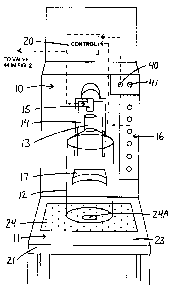
Figure 1 is an isometric view of a dispensing stand according to the
present invention.
Figure 2 is a cross sectional view through a portion of the dispensing
stand showing the base of the dispensing location through which the neck of a
bottle
extends into the sanitizing section beneath the base.
In the drawings like characters of reference indicate corresponding parts

CA 02516201 2005-08-15
in the different figures.
DETAILED DESCRIPTION
In Figure 1 is shown a stand 10 having a base 11 on which a bottle 12 can
sit with the neck 13 of the bottle projecting into a channel 14 at which is
located a
dispensing nozzle 15. The mouth of the neck is located just below the nozzle
so that
the liquid from the nozzle can be dispensed into the bottle for filling the
bottle. A series
of manually operable switches 16 is provided. These include the following
designations
so that the user can operate the required switch to fill the bottle to the
required position.
The designations are as follows:
Top up
18.9 litres
11.4 litres
8 litres
3.79 litres
Stop
Thus the user can press a selected one of the switches to fill a
predetermined size of bottle with the required quantity or can press the "top
up button"
which is a press and hold switch to provide a continuous supply of water into
the bottle
until the bottle is filled. The stop button can be pressed to halt flow in an
emergency
situation or when the flow is required to be halted.
The stand includes a cradle 17 which engages a side wall of the bottle so
that it is properly located underneath the nozzle at the required position so
as to fill by
the nozzle.
The dispensing system may be a coin fed system or may be simply a
custom operated system with the funds for the supply being collected by a
cashier
generally overseeing the filling of the bottles and the removal of the bottles
when filled
from the filling location to the customer vehicle.

CA 02516201 2005-08-15
The nozzle 15 is controlled by a control system 20 shown schematically
which is activated by the switches 16 and by the coin-freed system if present.
In addition to the dispensing system shown, there is provided a sanitizing
system underneath the base 11. The base 11 comprises a surrounding frame 21
with a
tray 22 recessed from the top surface 23 of the surrounding frame. The tray 22
is
covered by a panel 24 which sits on a rim of the frame surrounding the tray so
that the
panel and the frame provide a flat surface onto which the bottle can be placed
and slide
across the flat surface. The panel 24 is preferably perforated so as to allow
any water
or liquid collecting on the surface to flow into the tray and away from the
base 11.
At the bottom of the tray which is inclined downwardly to the bottom is
provided a drain opening 26 which is generally cylindrical and forms a
receptacle 27 into
which water within the tray can flow to an annular drain opening 28. The
annular drain
opening is located at the bottom of the receptacle and is connected to a
suitable
collection duct or pipe for transfer of liquid entering the drain opening away
from the tray
22 to a suitable discharge location. At the center of the annular opening 28
is provided
a pipe 29 which stands upwardly in a coaxial arrangement through the drain
opening
and provides a nozzle 30 at the top of the pipe 29. Thus the nozzle 30 is
located above
the annular drain opening 28 and above the receptacle 27. The top of the
nozzle is
however below the panel 24. The panel 24 has a hole 24A directly above the
nozzle
with a diameter of the hole 24A arranged to receive the neck of a bottle of
the type to be
filled.
Within the receptacle 27 at a position just above a bottom surface 32 of
the receptacle is provided a lever 33 of a switch 35. Thus when a bottle is
inverted and
its neck inserted through the hole 24A into the receptacle 27, the mouth of
the bottle
engages the lever 33 and presses the lever 33 down onto the bottom surface 32
of the
receptacle. This activates the switch 35 so that the switch acts as a detector
for the
presence of the bottle in its inverted position having its mouth in the
receptacle and its

CA 02516201 2005-08-15
neck over the nozzle 30.
The stand 10 provides a pair of switches 40 and 41 accessible to the
customer which are designated "sanitize" and "rinse" respectively. The control
system
20 is connected to the switches 40 and 41 so that actuation of the switches by
the
customer provides firstly a sanitizing liquid to be injected through the
nozzle 30 into the
bottle followed by a rinsing liquid to be injected into the bottle. The
rinsing liquid is
usually the product water so that the bottle is rinsed to a condition which is
free of any
extraneous taste from the rinsing liquid. The control system controls a valve
44 which
controls the supply of rinsing liquid from a supply 45 through pipes 46 and 29
to the
nozzle 30. A pump 47 can add sanitizing liquid to the liquid in the pipe 46.
Thus the
customer can operate the switches to supply the sanitizing liquid comprising
the supply
water and the sanitizing agent initially into the bottle to provide a cleaning
action. This
can only occur in the event that the switch 35 is activated by the lever 33
thus detecting
the presence of the bottle in order that sanitizing liquid and rinsing liquid
cannot be
sprayed inadvertently or maliciously from the nozzle 30 when no bottle is in
place.
In the inverted position the bottle rests against the cradle 17 so as to hold
it generally upright with the mouth sitting on the bottom of the receptacle.
Since various modifications can be made in my invention as herein above
described, and many apparently widely different embodiments of same made
within the
spirit and scope of the claims without department from such spirit and scope,
it is
intended that all matter contained in the accompanying specification shall be
interpreted
as illustrative only and not in a limiting sense.

Representative Drawing
A single figure which represents the drawing illustrating the invention.
Administrative Status

2024-08-01:As part of the Next Generation Patents (NGP) transition, the Canadian Patents Database (CPD) now contains a more detailed Event History, which replicates the Event Log of our new back-office solution.

Please note that "Inactive:" events refers to events no longer in use in our new back-office solution.

For a clearer understanding of the status of the application/patent presented on this page, the site Disclaimer , as well as the definitions for Patent , Event History , Maintenance Fee  and Payment History  should be consulted.

Event History

Description Date
Application Not Reinstated by Deadline 2009-08-17
Time Limit for Reversal Expired 2009-08-17
Deemed Abandoned - Failure to Respond to Maintenance Fee Notice 2008-08-15
Inactive: Correspondence - Formalities 2007-07-19
Inactive: Correspondence - Formalities 2007-07-11
Application Published (Open to Public Inspection) 2007-02-15
Inactive: Cover page published 2007-02-14
Inactive: First IPC assigned 2006-08-10
Inactive: IPC assigned 2006-08-10
Filing Requirements Determined Compliant 2005-09-30
Inactive: Filing certificate - No RFE (English) 2005-09-30
Application Received - Regular National 2005-09-30
Small Entity Declaration Determined Compliant 2005-08-15

Abandonment History

Abandonment Date Reason Reinstatement Date
2008-08-15

Maintenance Fee

The last payment was received on 2007-07-25

Note : If the full payment has not been received on or before the date indicated, a further fee may be required which may be one of the following

  • the reinstatement fee;
  • the late payment fee; or
  • additional fee to reverse deemed expiry.

Please refer to the CIPO Patent Fees web page to see all current fee amounts.

Fee History

Fee Type Anniversary Year Due Date Paid Date
Application fee - small 2005-08-15
MF (application, 2nd anniv.) - small 02 2007-08-15 2007-07-25
Owners on Record

Note: Records showing the ownership history in alphabetical order.

Current Owners on Record
MICHAEL I. HOFFER
Past Owners on Record
None
Past Owners that do not appear in the "Owners on Record" listing will appear in other documentation within the application.
Documents

To view selected files, please enter reCAPTCHA code :


To view images, click a link in the Document Description column. To download the documents, select one or more checkboxes in the first column and then click the "Download Selected in PDF format (Zip Archive)" or the "Download Selected as Single PDF" button.

List of published and non-published patent-specific documents on the CPD .

If you have any difficulty accessing content, you can call the Client Service Centre at 1-866-997-1936 or send them an e-mail at CIPO Client Service Centre.


Document
Description 
Date
(yyyy-mm-dd) 
Number of pages   Size of Image (KB) 
Description 2005-08-15 6 238
Abstract 2005-08-15 1 18
Claims 2005-08-15 2 70
Drawings 2005-08-15 2 29
Representative drawing 2007-01-23 1 7
Cover Page 2007-02-06 1 36
Filing Certificate (English) 2005-09-30 1 157
Reminder of maintenance fee due 2007-04-17 1 109
Courtesy - Abandonment Letter (Maintenance Fee) 2008-10-14 1 174
Correspondence 2007-07-11 2 40
Correspondence 2007-07-19 2 43