Note: Descriptions are shown in the official language in which they were submitted.
CA 02516215 2007-07-17
FAN ARRAY FAN SECTION IN AIR-HANDLING SYSTEMS
BACKGROUND OF INVENTION
The present invention is directed to a fan array fan section utilized in an
air-
handling system.
Air-handling systems (also referred to as an air handier) have traditionally
been
used to condition buildings or rooms (hereinafter referred to as
'structures"). An air-handling
system is defined as a structure that includes components designed to work
together in order to
condition air as part of the primary system for ventilation of structures. The
air-handling system
may contain components such as cooling coils, heating coils, filters,
humidifiers, fans, sound
attenuators, controls, and other devices functioning to meet the needs of the
structures. The
air-handling system may be manufactured in a factory and brought to the
structure to be
installed or it may be built on site using the necessary devices to meet the
functioning needs of
the structure. The air-handling compartment 102 of the air-handling system
includes the inlet
plenum 112 prior to the fan inlet cone 104 and the discharge plenum 110.
Within the air-
handling compartment 102 is situated the fan unit 100 (shown as an inlet cone
104, a fan 106,
and a motor 108), fan frame, and any appurtenance associated with the function
of the fan (e.g.
dampers, controls, settling means, and associated cabinetry). Within the fan
106 Is a fan wheel
(not shown) having at least one blade. The fan wheel has a fan wheel diameter
that is
measured from one side of the outer periphery of the fan wheel to the opposite
side of the outer
periphery of the fan wheel. The dimensions of the handling compartment 102
such as height,
width, and airway length are determined by consulting fan manufacturers data
for the type of fan
selected.
FIG. I shows an exemplary prior art air-handling system having a single fan
unit
100 housed in an air-handling compartment 102. For exemplary purposes, the fan
unit 100 is
shown having an inlet cone 104, a fan 106, and a motor 108. Larger structures,
structures
requiring greater air volume, or structures requiring higher or lower
temperatures have generally
needed a larger fan unit 100 and a generally correspondingly larger air-
handling compartment
102.
As shown in FIG. 1, an air-handling compartment 102 is substantially divided
into
a discharge plenum 110 and an inlet plenum 112. The combined discharge plenum
110 and the
inlet plenum 112 can be referred to as the airway path 120. The fan unit 100
may be situated in
the discharge plenum 110 as shown), the inlet plenum 112, or partially within
the inlet plenum
112 and partially within the discharge plenum 110. The portion of the airway
path 120 in which
the fan unit 100 is positioned may be generically referred to as the "fan
section' (indicated by
Page 1
CA 02516215 2007-07-17
reference numeral 114). The size of the inlet cone 104, the size of the fan
106, the size the
motor 108, and the size of the fan frame (not shown) at least partially
determine the length of
the airway path 120. Filter banks 122 and/or cooling coils (not shown) may be
added to the
system either upstream or downstream of the fan units 100.
For example, a first exemplary structure requiring 50,000 cubic feet per
minute of
airflow at six (6) inches water gage pressure would generally require a prior
art air-handling
compartment 102 large enough to house a 55 Inch impeller, a 100 horsepower
motor, and
supporting framework. The prior art air-handling compartment 102, in turn
would be
approximately 92 inches high by 114 to147 inches wide and 106 to 112 inches
long. The
minimum length of the air-handling compartment 102 and/or airway path 120
would be dictated
by published manufacturers data for a given fan type, motor size, and
application. Prior art
cabinet sizing guides show exemplary rules for configuring an air-handling
compartment 102.
These rules are based on optimization, regulations, and experimentation.
For example, a second exemplary structure includes a recirculation air handier
used in semiconductor and pharmaceutical clean rooms requiring 26,000 cubic
feet per minute
at two (2) inches water gage pressure. This structure would generally require
a prior art air-
handling system with a air-handling compartment 102 large enough to house a 44
inch impeller,
a 25 horsepower motor, and supporting framework. The prior art air-handling
compartment 102,
in turn would be approximately 78 inches high by 99 inches wide and 94 to 100
inches long.
The minimum length of the air-handling compartment 102 and/or airway path 120
would be
dictated by published manufacturers data for a given fan type, motor size and
application. Prior
art cabinet sizing guides show exemplary rules for configuring an air-handling
compartment 102.
These rules are based on optimization, regulations, and experimentation.
These prior art air-handling systems have many problems including the
following
exemplary problems:
= Because real estate (e.g. structure space) is extremely expensive, the
larger size of the air-handling compartment 102 is extremely undesirable.
= The single fan units 100 are expensive to produce and are generally
custom produced for each job.
Single fan units 100 are expensive to operate.
= Single fan units 100 are inefficient in that they only have optimal or peak
efficiency over a small portion of their operating range.
= If a single fan unit 100 breaks down, there is no air conditioning at all.
Page 2
CA 02516215 2007-07-17
The low frequency sound of the large fan unit 100 is hard to attenuate.
= The high mass and turbulence of the large fan unit 100 can cause
undesirable vibration.
Height restrictions have necessitated the use of air-handling systems built
with
two fan units 100 arranged horizontally adjacent to each other. It should be
noted, however,
that a good engineering practice is to design air handler cabinets and
discharge plenums 110 to
be symmetrical to facilitate more uniform airflow across the width and height
of the cabinet.
Twin fan units 100 have been utilized where there is a height restriction and
the unit is designed
with a high aspect ratio to accommodate the desired flow rate. As shown in the
Greenheck
`Installation Operating and Maintenance Manual,' if side-by-side installation
was contemplated,
there were specific instructions to arrange the fans such that there was at
least one fan wheel
diameter spacing between the fan wheels and at least one half a fan wheel
diameter between
the fan and the walls or ceilings. The Greenheck reference even specifically
states that
arrangements "with less spacing will experience performance losses.' Normally,
the air-
handling system and air-handling compartment 102 are designed for a uniform
velocity gradient
of 500 feet per minute velocity in the direction of airflow. The two fan unit
100 air-handling
systems, however, still substantially suffered from the problems of the single
unit embodiments.
There was no recognition of advantages by increasing the number of fan units
100 from one to
two. Further, the two fan unit 100 section exhibits a non-uniform velocity
gradient in the region
following the fan unit 100 that creates uneven airflow across filters, coils,
and sound attenuators.
It should be noted that electrical devices have taken advantage of multiple
fan
cooling systems. For example, U.S. Patent No. 6,414,845 to Bonet uses a
multiple-fan modular
cooling component for installation in multiple component bay electronic
devices. Although some
of the advantages realized in the Bonet system would be realized in the
present system, there
are significant differences. For example, the Bonet system is designed to
facilitate electronic
component cooling by directing the output from each fan to a specific device
or area. The Bonet
system would not work to direct airflow to all devices in the direction of
general airflow. Other
patents such as U.S. Patent No. 4,767,262 to Simon and U.S. Patent No.
6,388,880 to El-
Ghobashy et al. teach fan arrays for use with electronics.
Even in the computer and machine industries, however, operating fans in
parallel
is taught against as not providing the desired results except in low system
resistance situations
where fans operate in near free delivery. For example, Sunon Group has a web
page in which
they show two axial fans operating in parallel, but specifically state that if
"the parallel fans are
Page 3
CA 02516215 2007-07-17
applied to the higher system resistance that [an] enclosure has, ... less
Increase in flow results
with parallel fan operation.' Similar examples of teaching against using fans
in parallel are
found in an article accessible from HighBeam Research's library
(http:ilstad.highbeam.com) and
an article by Ian McLeod accessible at (httpJiwww.papstplc.com).
Page 4
CA 02516215 2009-05-01
BRIEF SUMMARY OF THE INVENTION
The present invention provides a fan array fan section in an air-
handling system comprising: an air-handling compartment; a plurality of fan
units; said plurality of fan units arranged in a fan array; said fan array
positioned within said air-handling compartment; said air-handling
compartment associated with a structure such that said air-handling system
conditions the air of said structure; and a control system for operating said
plurality of fan units at substantially peak efficiency by turning on and off
selective ones of said plurality of fan units.
The present invention also provides a fan array fan section in
an air-handling system comprising: an air-handling compartment; a plurality
of fan units; said plurality of fan units arranged in a fan array; said fan
array
positioned within said air-handling compartment; said air-handling
compartment association with a structure such that the said air-handling
system conditions the air of said structure; and a control system for
controlling said plurality of fan units, said control system allowing control
of
the speed of the fan units in said plurality of fan units such that they run
at
substantially peak efficiency.
The present invention also provides a fan array fan section in
an air-handling system comprising: an air-handling compartment; a plurality
of independently controllable fan units; said plurality of fan units arranged
in
a fan array; said fan array positioned within said air-handling compartment;
said air-handling compartment associated with a structure such that the said
air-handling system conditions the air of said structure; and a control system
5
CA 02516215 2010-02-10
for controlling the speed of the fan units in said plurality of fan units such
that
they run at substantially peak efficiency.
The present invention also provides a fan array fan section in
an air-handling system comprising: at least six fan units; said at least six
fan
units arranged in a fan array; an air-handling compartment within which said
fan array of fan units is positioned; and an array controller for controlling
said
at least six fan units to run at substantially peak efficiency by turning
selective ones of said at least six fan units on and off, wherein each fan
unit
has a peak efficiency operating range outside of which it operates at a
reduced efficiency, and wherein said array controller is programmed to
operate said at least six fan units at substantially peak efficiency by
turning
off at least one fan unit operating at reduced efficiency and running the
remaining fan units within said peak efficiency operating range.
The present invention also provides a fan array fan section in
an air-handling system comprising: a plurality of independently controllable
fan units, each fan unit comprising an inlet cone, a fan, and a motor; said
plurality of fan units arranged in a fan array; an air-handling compartment
within which said fan array of fan units is positioned; an array controller
for
controlling said plurality of fan units to run at substantially peak
efficiency by
turning selective ones of said plurality of fan units on and off; wherein each
of
said plurality of fan units has a fan wheel diameter, wherein spacing between
said plurality of fan units is less than 60% of said fan wheel diameter.
The present invention also provides an air handling system
comprising: a plurality of individual fan units; said plurality of fan units
arranged in a fan array; and a control system for controlling selected fan
units in said array of fan units in a manner such that the remaining fans in
said plurality of fan units run at substantially peak efficiency.
In a further aspect, the present invention provides a method of
providing air to a space comprising: providing a plurality of independently
controllable fan units arranged in a fan array such that air flow from all of
said
fan units flows in substantially all of said space; and turning selected ones
of
6
CA 02516215 2009-05-14
said fan units off in a manner such that the remaining fan units in said
plurality of fan units run at substantially peak efficiency.
The present invention also provides a method of providing air
into a space comprising: providing a plurality of independently controllable
fan units arranged in a fan array such that air flow from all of said fan
units
flows in substantially all of said space; and controlling selected fan units
in
said array of fan units such that the remaining fan units in said plurality of
fan
units run at substantially peak efficiency.
The foregoing and other features and advantages of the
invention will be more readily understood upon consideration of the following
detailed description of the invention, taken in conjunction with the
accompanying drawings.
6a
CA 02516215 2005-08-12
WO 2004/085928 PCT/US2004/008578
BRIEF DESCRIPTION OF THE SEVERAL VIEWS OF THE DRAWINGS
FIG. I is a side view of an exemplary prior art air-handling system having a
single large fan unit within an air-handling compartment.
FIG. 2 is a side view of an exemplary fan array fan section in an air-handling
system of the present invention having a plurality of small fan units within
an air-handling
compartment.
FIG. 3 is a plan or elevation view of a 4x6 exemplary fan array fan section in
an
air-handling system of the present invention having a plurality of small fan
units within an air-
handling compartment.
FIG. 4 is a plan or elevation view of a 5x5 exemplary fan array fan section in
an
air-handling system of the present invention having a plurality of small fan
units within an air-
handling compartment.
FIG. 5 is a plan or elevation view of a 3x4 exemplary fan array fan section in
an
air-handling system of the present invention having a plurality of small fan
units within an air-
handling compartment.
FIG. 6 is a plan or elevation view of a 3x3 exemplary fan array fan section in
an
air-handling system of the present invention having a plurality of small fan
units within an air-
handling compartment.
FIG. 7 is a plan or elevation view of a 3x1 exemplary fan array fan section in
an
air-handling system of the present invention having a plurality of small fan
units within an air-
handling compartment.
FIG. 8 is a plan or elevation view of an alternative exemplary fan array fan
section in an air-handling system of the present invention in which a
plurality of small fan units
are arranged in a spaced pattern array within an air-handling compartment.
FIG. 9 is a plan or elevation view of an alternative exemplary fan array fan
section in an air-handling system of the present invention in which a
plurality of small fan units
are arranged in a checker board array within an air-handling compartment.
FIG. 10 is a plan or elevation view of an alternative exemplary fan array fan
section in an air-handling system of the present invention in which a
plurality of small fan units
are arranged in rows slightly offset array within an air-handling compartment.
FIG. 11 is a plan or elevation view of an alternative exemplary fan array fan
section in an air-handling system of the present invention in which a
plurality of small fan units
are arranged in columns slightly offset array within an air-handling
compartment.
Page 7
CA 02516215 2005-08-12
WO 2004/085928 PCT/US2004/008578
FIG. 12 is a plan or elevation view of a 5x5 exemplary fan array fan section
in an
air-handling system of the present invention running at 52% capacity by
turning a portion of the
fans on and a portion of the fans off.
FIG. 13 is a plan or elevation view of a 5x5 exemplary fan array fan section
in an
air-handling system of the present invention running at 32% capacity by
turning a portion of the
fans on and a portion of the fans off.
FIG. 14 is a side view of an alternative exemplary fan array fan section in an
air-
handling system of the present invention having a plurality of staggered small
fan units within an
air-handling compartment.
Page 8
CA 02516215 2005-08-12
WO 2004/085928 PCT/US2004/008578
DETAILED DESCRIPTION OF THE INVENTION
The present invention is directed to a fan array fan section in an air-
handling
system. As shown in FIGS. 2-11, the fan array fan section in the air-handling
system uses a
plurality of individual single fan units 200. In one preferred embodiment, the
fan units 200 are
arranged in a true array (FIGS. 3-7), but alternative embodiments may include,
for example,
alternative arrangements such as in a spaced pattern (FIG. 8), a checker board
(FIG. 9), rows
slightly offset (FIG. 10), or columns slightly offset (FIG. 11). As the
present invention could be
implemented with true arrays and/or alternative arrays, the term "array" is
meant to be
comprehensive.
The fan units 200 in the fan array of the present invention may be spaced as
little
as 20% of a fan wheel diameter. Optimum operating conditions for a closely
arranged array
may be found at distances as low as 30% to 60% of a fan wheel diameter. By
closely spacing
the fan units 200, more air may be moved in a smaller space. For example, if
the fan wheels of
the fan units 200 have a 20 inch fan wheel diameter, only a 4 inch space (20%)
is needed
between the outer periphery of one fan wheel and the outer periphery of the
adjacent fan wheel
(or a 2 inch space between the outer periphery of a fan wheel and an the
adjacent wall or
ceiling).
By using smaller fan units 200 it is possible to support the fan units 200
with less
intrusive structure (fan frame). This can be compared to the large fan frame
that supports prior
art fan units 100 and functions as a base. This large fan frame must be large
and sturdy
enough to support the entire weight of the prior art fan units 100. Because of
their size and
position, the known fan frames cause interference with air flow. In the
preferred embodiment,
therefore, the fan units 200 of the fan array may be supported by a frame that
supports the
motors 108 with a minimum restriction to airflow.
As mentioned in the Background, others have tried using side-by-side
installation
of two fan units 100 arranged horizontally adjacent to each other within an
air-handling system.
As is also mentioned in the Background, fan arrays have been used in
electronic and computer
assemblies. However, in the air-handling system industry, it has always been
held that there
must be significant spacing between the horizontally arranged fan wheels and
that
arrangements with less spacing will experience performance losses. A single
large fan moves
all the air in a cabinet. Using two of the same or slightly smaller fans
caused the air produced
by one fan to interfere with the air produced by the other fan. To alleviate
the interference
problem, the fans had to be spaced within certain guidelines - generally
providing a clear space
Page 9
CA 02516215 2005-08-12
WO 2004/085928 PCT/US2004/008578
between the fans of a distance of at least one wheel diameter (and a half a
wheel diameter to
an adjacent wall). Applying this logic, it would not have made sense to add
more fans. And
even if additional fans had been added, the spacing would have continued to be
at least one
wheel diameter between fans. Further, in the air-handling system industry,
vertically stacking
fan units would have been unthinkable because the means for securing the fan
units would not
have been conducive to such stacking (they are designed to be positioned on
the floor only).
It should be noted that the plenum fan is the preferred fan unit 200 of the
present
invention. In particular, the APF-121, APF-141, APF-161, and APF-181 plenum
fans
(particularly the fan wheel and the fan cone) produced by Twin City Fan
Companies, Ltd. of
Minneapolis, Minnesota, U.S. has been found to work well. The reason that
plenum fans work
best is that they do not produce points of high velocity such as those
produced by axial fans and
housed centrifugal fans and large plenum fans. Alternative embodiments use
known fan units
or fan units yet to be developed that will not produce high velocity gradients
in the direction of
airflow. Still other embodiments, albeit less efficient, use fan units such as
axial fans and/or
centrifugal housed fans that have points of high velocity in the direction of
airflow.
In the preferred embodiment, each of the fan units 200 in the fan array fan
section in the air-handling system is controlled by an array controller 300
(FIGS. 12 and 13). In
one preferred embodiment, the array controller 300 may be programmed to
operate the fan
units 200 at peak efficiency. In this peak efficiency embodiment, rather than
running all of the
fan units 200 at a reduced efficiency, the array controller 300 turns off
certain fan units 200 and
runs the remaining fan units 200 at peak efficiency. In an alternative
embodiment, the fan units
200 could all run at the same power level (e.g. efficiency and/or flow rate)
of operation.
Another advantage of the present invention is that the array controller 300
(which
may be a variable frequency drive (VFD)) used for controlling fan speed and
thus flow rate and
pressure, could be sized for the actual brake horsepower of the fan array fan
section in the air-
handling system. Since efficiency of the fan wall array can be optimized over
a wide range of
flow rates and pressures, the actual operating power consumed by the fan array
is substantially
less than the actual operating power consumed by the comparable prior art air-
handling
systems and the array controller's power could be reduced accordingly. The
array controller
300 could be sized to the actual power consumption of the fan array where as
the controller
(which may have been a variable frequency drive) in a traditional design would
be sized to the
maximum nameplate rating of the motor per Electrical Code requirements. An
example of a
prior art fan design supplying 50,000 cubic feet per minute of air at 2.5
inches pressure, would
Page 10
CA 02516215 2005-08-12
WO 2004/085928 PCT/US2004/008578
require a 50 horsepower motor and 50 horsepower controller. The new invention
will preferably
use an array of fourteen 2 horsepower motors and a 30 horsepower array
controller 300.
This invention solves many of the problems of the prior art air-handling
systems
including, but not limited to real estate, reduced production costs, reduced
operating expenses,
increased efficiency, improved airflow uniformity, redundancy, sound
attenuation advantages,
and reduced vibration.
Controllability
As mentioned, preferably each of the fan units 200 in the fan array fan
section in
the air-handling system is controlled by an array controller 300 (FIGS. 12 and
13) that may be
programmed to operate the fan units 200 at peak efficiency. In this peak
efficiency
embodiment, rather than running all of the fan units 200 at a reduced
efficiency, the array
controller 300 is able to turn off certain fan units 200 and run the remaining
fan units 200 at
peak efficiency. Preferably, the array controller 300 is able to control fan
units 200 individually,
in predetermined groupings, and/or as a group as a whole.
For example, in the 5x5 fan array such as that shown in FIGS. 4, 12, and 13, a
person desiring to control the array may select desired air volume, a level of
air flow, a pattern
of air flow, and/or how many fan units 200 to operate. Turning first to air
volume, each fan unit
200 in a 5x5 array contributes 4% of the total air. In variable air volume
systems, which is what
most structures have, only the number of fan units 200 required to meet the
demand would
operate. A control system (that may include the array controller 300) would be
used to take fan
units 200 on line (an "ON" fan unit 200) and off line (an "OFF" fan unit 200)
individually. This
ability to turn fan units 200 on and off could effectively eliminate the need
for a variable
frequency drive. Similarly, each fan unit 200 in a 5x5 array uses 4% of the
total power and
produces 4% of the level of air flow. Using a control system to take fan units
200 on line and off
line allows a user to control power usage and/or air flow. The pattern of air
flow can also be
controlled if that would be desirable. For example, depending on the system it
is possible to
create a pattern of air flow only around the edges of a cabinet or air only at
the top. Finally,
individual fan units 200 may be taken on line and off line. This
controllability may be
advantageous if one or more fan units 200 are not working properly, need to be
maintained (e.g.
needs general service), and/or need to be replaced. The problematic individual
fan units 200
may be taken off line while the remainder of the system remains fully
functional. Once the
individual fan units 200 are ready for use, they may be brought back on line.
Page 11
CA 02516215 2005-08-12
WO 2004/085928 PCT/US2004/008578
A further advantage to taking fan units 200 on and off line occurs when
building
or structure control systems require low volumes of air at relatively high
pressures. In this case,
the fan units 200 could be modulated to produce a stable operating point and
eliminate the
surge effects that sometimes plague structure owners and maintenance staff.
The surge effect
is where the system pressure is too high for the fan speed at a given volume
and the fan unit
200 has a tendency to go into stall.
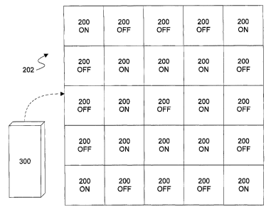
Examples of controllability are shown in FIGS. 12 and 13. In the fan array fan
section in the air-handling system shown in FIG. 12, the array controller 300
alternates "ON" fan
units 200 and "OFF" fan units 200 in a first exemplary pattern as shown so
that the entire
system is set to operate at 52% of the maximum rated air flow but only
consumes 32% of full
rated power. These numbers are based on exemplary typical fan operations in a
structure.
FIG. 13 shows the fan array fan section in the air-handling system set to
operate at 32% of the
maximum rated air flow but only consumes 17% of full rated power. These
numbers are based
on exemplary typical fan operations in a structure. In this embodiment, the
array controller 300
creates a second exemplary pattern of "OFF" fan units 200 and "ON" fan units
200 as shown.
Real Estate
The fan array fan section in the air-handling section 220 of the present
invention
preferably uses (60% to 80%) less real estate than prior art discharge plenums
120 (with the
hundred series number being prior art as shown in FIG. 1 and the two hundred
series number
being the present invention as shown in FIG. 2) in air-handling systems.
Comparing the prior
art (FIG. 1) and the present invention (FIG. 2) shows a graphical
representation of this
shortening of the airway path 120, 220. There are many reasons that using
multiple smaller fan
units 200 can reduce the length of the airway path 120, 220. For example,
reducing the size of
the fan unit 100, 200 and motor 108, 208 reduces the length of the discharge
plenum 110, 210.
Similarly, reducing the size of the inlet cone 104, 204 reduces the length of
the inlet plenum
112, 212. The length of the discharge plenum 110, 210 can also be reduced
because air from
the fan array fan section in the air-handling system of the present invention
is substantially
uniform whereas the prior art air-handling system has points of higher air
velocity and needs
time and space to mix so that the flow is uniform by the time it exits the air-
handling
compartment 102, 202. (This can also be described as the higher static
efficiency in that the
present invention eliminates the need for settling means downstream from the
discharge of a
prior art fan system because there is little or no need to transition from
high velocity to low
Page 12
CA 02516215 2005-08-12
WO 2004/085928 PCT/US2004/008578
velocity.) The fan array fan section in the air-handling system takes in air
from the inlet plenum
212 more evenly and efficiently than the prior art air-handling system so that
the length of the
inlet plenum 112, 212 may be reduced.
For purposes of comparison, the first exemplary structure set forth in the
Background of the Invention (a structure requiring 50,000 cubic feet per
minute of airflow at a
pressure of six (6) inches water gage) will be used. Using the first exemplary
structure, an
exemplary embodiment of the present invention could be served by a nominal
discharge plenum
210 of 89 inches high by 160 inches wide and 30 to 36 inches long (as compared
to 106 to 112
inches long in the prior art embodiments). The discharge plenum 210 would
include a 3x4 fan
array fan section in the air-handling system such as the one shown in FIG. 5)
having 12 fan
units 200. The space required for each exemplary fan unit 200 would be a
rectangular cube of
approximately 24 to 30 inches on a side depending on the array configuration.
The airway path
220 is 42 to 48 inches (as compared to 88 to 139 inches in the prior art
embodiments).
For purposes of comparison, the second exemplary structure set forth in the
Background of the Invention (a structure requiring 26,000 cubic feet per
minute of airflow at a
pressure of two (2) inches water gage) will be used. Using the second
exemplary structure, an
exemplary embodiment of the present invention could be served by a nominal
discharge plenum
210 of 84 inches high by 84 inches wide, and and 30 to 36 inches long (as
compared to 94 to
100 inches long in the prior art embodiments). The discharge plenum would
include a 3x3 fan
array fan section in the air-handling system (such as the one shown in FIG. 6)
having 9 fan units
200. The space required for each exemplary fan unit 200 would be a rectangular
cube of
approximately 24 to 30 inches on a side depending on the array configuration.
The airway path
220 is 42 to 48 inches (as compared to 71 to 95 inches in the prior art
embodiments).
Reduced Production Costs
It is generally more cost effective to build the fan array fan section in the
air-
handling system of the present invention as compared to the single fan unit
100 used in prior art
air-handling systems. Part of this cost savings may be due to the fact that
individual fan units
200 of the fan array can be mass-produced. Part of this cost savings may be
due to the fact
that it is less expensive to manufacture smaller fan units 200. Whereas the
prior art single fan
units 100 were generally custom built for the particular purpose, the present
invention could be
implemented on a single type of fan unit 200. In alternative embodiments,
there might be
several fan units 200 having different sizes and/or powers (both input and
output). The different
Page 13
CA 02516215 2005-08-12
WO 2004/085928 PCT/US2004/008578
fan units 200 could be used in a single air-handling system or each air-
handling system would
have only one type of fan unit 200. Even when the smaller fan units 200 are
custom made, the
cost of producing multiple fan units 200 for a particular project is almost
always less that the
cost of producing a single large prior art fan unit 100 for the same project.
This may be because
of the difficulties of producing the larger components and/or the cost of
obtaining the larger
components necessary for the single large prior art fan unit 100. This cost
savings also extends
to the cost of producing a smaller air-handling compartment 202.
In one preferred embodiment of the invention, the fan units 200 are modular
such
that the system is "plug and play." Such modular units may be implemented by
including
structure for interlocking on the exterior of the fan units 200 themselves.
Alternatively, such
modular units may be implemented by using separate structure for interlocking
the fan units
200. In still another alternative embodiment, such modular units may be
implemented by using
a grid system into which the fan units 200 may be placed.
Reduced Operating Expenses
The fan array fan section in the air-handling system of the present invention
preferably are less expensive to operate than prior art air-handling systems
because of greater
flexibility of control and fine tuning to the operating requirements of the
structure. Also, by using
smaller higher speed fan units 200 that require less low frequency noise
control and less static
resistance to flow.
Increased Efficiency
The fan array fan section in the air-handling system of the present invention
preferably is more efficient than prior art air-handling systems because each
small fan unit 200
can run at peak efficiency. The system could turn individual fan units 200 on
and off to prevent
inefficient use of particular fan units 200. It should be noted that an array
controller 300 could
be used to control the fan units 200. As set forth above, the array controller
300 turns off certain
fan units 200 and runs the remaining fan units 200 at peak efficiency.
Redundancy
Multiple fan units 200 add to the redundancy of the system. If a single fan
unit
200 breaks down, there will still be cooling. The array controller 300 may
take disabled fan units
200 into consideration such that there is no noticeable depreciation in
cooling or air flow rate.
Page 14
CA 02516215 2005-08-12
WO 2004/085928 PCT/US2004/008578
This feature may also be useful during maintenance as the array controller 300
may turn off fan
units 200 that are to be maintained offline with no noticeable depreciation in
cooling or airflow
rate.
Sound Attenuation Advantages
The high frequency sound of the small fan units 200 is easier to attenuate
than
the low frequency sound of the large fan unit. Because the fan wall has less
low frequency
sound energy, shorter less costly sound traps are needed to attenuate the
higher frequency
sound produced by the plurality of small fan units 200 than the low frequency
sound produced
by the single large fan unit 100. The plurality of fan units 200 will each
operate in a manner
such that acoustic waves from each unit will interact to cancel sound at
certain frequencies thus
creating a quieter operating unit than prior art systems.
Reduced Vibration
The multiple fan units 200 of the present invention have smaller wheels with
lower mass and create less force due to residual unbalance thus causing less
vibration than the
large fan unit. The overall vibration of multiple fan units 200 will transmit
less energy to a
structure since individual fans will tend to cancel each other due to slight
differences in phase.
Each fan unit 200 of the multiple fan units 200 manage a smaller percentage of
the total air
handling requirement and thus produce less turbulence in the air stream and
substantially less
vibration.
It should be noted that FIG. 3 shows a 4x6 fan array fan section in the air-
handling system having twenty-four fan units 200, FIG. 4 shows a 5x5 fan array
fan section in
the air-handling system having twenty-five fan units 200, FIG. 5 shows a 3x4
fan array fan
section in the air-handling system having twelve fan units 200, FIG. 6 shows a
3x3 fan array fan
section in the air handling system having nine fan units 200, and FIG. 7 shows
a 3x1 fan array
fan section in the air-handling system having three fan units 200. It should
be noted that the
array may be of any size or dimension of more than two fan units 200. It
should be noted, that
although the fan units 200 may be arranged in a single plane (as shown in FIG.
2), an
alternative array configuration could contain a plurality of fan units 200
that are arranged in a
staggered configuration (as shown in FIG. 14) in multiple planes. It should be
noted that cooling
coils (not shown) could be added to the system either upstream or downstream
of the fan units
Page 15
CA 02516215 2005-08-12
WO 2004/085928 PCT/US2004/008578
200. It should be noted that, although shown upstream from the fan units 200,
the filter bank
122, 222 could be downstream.
It should be noted that an alternative embodiment would use a horizontally
arranged fan array. In other words, the embodiments shown in FIGS. 2-14 could
be used
horizontally or vertically or in any direction perpendicular to the direction
of air flow. For
example, if a vertical portion of air duct is functioning as the air-handling
compartment 202, the
fan array may be arranged horizontally. This embodiment would be particularly
practical in an
air handling compartment for a return air shaft.
It should be noted that the fan section 214 may be any portion of the airway
path
220 in which the fan units 200 are positioned. For example, the fan units 200
may be situated in
the discharge plenum 210 (as shown), the inlet plenum 212, or partially within
the inlet plenum
212 and partially within the discharge plenum 210. It should also be noted
that the air-handling
compartment 202 may be a section of air duct.
The terms and expressions that have been employed in the foregoing
specification are used as terms of description and not of limitation, and are
not intended to
exclude equivalents of the features shown and described or portions of them.
The scope of the
invention is defined and limited only by the claims that follow.
Page 16