Language selection

Search

Patent 2516483 Summary

Third-party information liability

Some of the information on this Web page has been provided by external sources. The Government of Canada is not responsible for the accuracy, reliability or currency of the information supplied by external sources. Users wishing to rely upon this information should consult directly with the source of the information. Content provided by external sources is not subject to official languages, privacy and accessibility requirements.

Claims and Abstract availability

Any discrepancies in the text and image of the Claims and Abstract are due to differing posting times. Text of the Claims and Abstract are posted:

  • At the time the application is open to public inspection;
  • At the time of issue of the patent (grant).
(12) Patent Application: (11) CA 2516483
(54) English Title: END CAP FOR ROOFING PANEL
(54) French Title: GARNITURE DE BOUT POUR PANNEAUX DE TOITURE
Status: Deemed Abandoned and Beyond the Period of Reinstatement - Pending Response to Notice of Disregarded Communication
Bibliographic Data
(51) International Patent Classification (IPC):
  • E04C 2/54 (2006.01)
  • E04D 3/06 (2006.01)
  • E04D 3/08 (2006.01)
(72) Inventors :
  • RICHARDSON, CHRISTOPHER (United Kingdom)
(73) Owners :
  • ULTRAFRAME (UK) LIMITED
(71) Applicants :
  • ULTRAFRAME (UK) LIMITED (United Kingdom)
(74) Agent: MARKS & CLERK
(74) Associate agent:
(45) Issued:
(86) PCT Filing Date: 2004-03-01
(87) Open to Public Inspection: 2004-09-16
Availability of licence: N/A
Dedicated to the Public: N/A
(25) Language of filing: English

Patent Cooperation Treaty (PCT): Yes
(86) PCT Filing Number: PCT/GB2004/000830
(87) International Publication Number: WO 2004079118
(85) National Entry: 2005-08-17

(30) Application Priority Data:
Application No. Country/Territory Date
0304752.9 (United Kingdom) 2003-03-01

Abstracts

English Abstract


An end cap (10) for use with ducted glazing panels comprises a channel section
member having an intended upper side wall (12), a base (14) and an intended
lower side wall (16), the upper and lower side walls being angled relative to
the base, whereby, when fitted to a glazing panel and the panel is installed
in a pitched roof, the base of the end cap is substantially vertical.


French Abstract

L'invention concerne une garniture de bout (10) destinée à être utilisée avec des panneaux de vitrage canalisés, qui comprend un élément de section de canal présentant une paroi latérale supérieure prévue (12); une base (14) et une paroi latérale inférieure prévue (16). Les parois latérales supérieure et inférieure sont inclinées relativement à la base, si bien que, lorsque la garniture de bout est fixée à un panneau de vitrage et le panneau installé dans une toiture inclinée, la base de la garniture de bout est sensiblement verticale.

Claims

Note: Claims are shown in the official language in which they were submitted.

6
Claims:
1. An end cap for use with ducted glazing panels comprising a channel
section member having an intended upper side wall, a base and an intended
lower side wall, the upper and lower side walls being angled relative to the
base,
whereby, when fitted to a glazing panel and the panel is installed in a
pitched
roof, the base of the end cap is substantially vertical.
2. An end cap as claimed in claim 1, wherein the free edge of the upper side
wall has gasket material thereon for sealing against a top surface of a
glazing
panel, in use.
3. An end cap as claimed in claim 2, wherein the gasket material is of rubber
or other suitable synthetic elastomeric material.
4. An end cap as claimed in claim 2 or 3, wherein the gasket material has its
free edge angled towards the lower side wall.
5. An end cap as claimed in any one of claims 1 to 4, wherein the lower side
wall has at least one strip or rib of gasket material on its inner surface for
sealing
against the underside of a glazing panel, in use.
6. An end cap as claimed in claim 5, wherein the gasket material is of rubber
or of synthetic elastomeric material.
7. An end cap as claimed in claim 5 or 6, wherein three strips of gasket
material are provided on the inner surface of the lower side wall.
8. An end cap as claimed in claim 5, 6 or 7, wherein the or each strip or rib
of gasket material is angled towards the base of the end cap.

9. An end cap as claimed in any one of claims 1 to 8, wherein the lower side
wall of the end cap has a first part that is normal to the base of the end cap
and
a second end part that is angled towards the upper side wall.
10. An end cap as claimed in any one of claims 1 to 9, wherein the free edge
of the lower side wall curves away from the upper side wall.
11. An end cap as claimed in any one of claims 1 to 10, wherein within the
end cap associated with the upper and lower side walls are a pair of
longitudinal
ribs to act as stops for a glazing panel, onto which the end cap is fitted.
12. An end cap as claimed in claim 11, wherein the stop of the lower side wall
is spaced from the base.
13. An end cap as claimed in claim 11 or 12, wherein the stop of the lower
side wall is in the region where the first and second parts of the lower side
wall
meet.
14. An end cap as claimed in any one of claims 1 to 12, wherein the lower
side wall has a series of drainage holes formed therein at spaced intervals
along
its length.
15. An end cap as claimed in claim 14, wherein the drainage holes are in the
aforesaid region where the first and second parts of the lower side wall meet.
16. An end cap for use with ducted glazing panels substantially as
hereinbefore described with reference to and as illustrated in the
accompanying
drawings.

Description

Note: Descriptions are shown in the official language in which they were submitted.


CA 02516483 2005-08-17
WO 2004/079118 PCT/GB2004/000830
END CAP FOR ROOFING PANEL
Description
This invention concerns installation of roofing panels.
Conservatories and like structures can have a roof structure comprising
glazing bars extending from one or both sides of a ridge member with glazing
panels supported between the glazing bars. A common glazing material is
polycarbonate sheeting, which may have two or three layers joined at their
edges and intermediate their edges to form longitudinal ducts through the
panels. When such panels are fitted to a conservatory roof, the ends of the
panels are sealed with a breather tape to prevent ingress of water and insects
into the ducts of the panels. The ends of the panels were then covered with a
simple polycarbonate cap.
However, polycarbonate panels are not completely flat, so that some
ingress of water was still p~ssible. In C~ ~~~~99~, ifi was pr~p~sed that end
caps for glazing panels comprise a channel section member having an intended
upper side and an intended lower side, the upper side including a co-extruded
gasket extending from and beyond its free edge, whereby, when the end cap is
pushed onto the glazing panel, the gasket lies on the panel surface to limit
passage of water past the gasket.
These end caps had a channel base that, in use, was generally normal to
the plane of the panel. A problem with that arrangement is that rain water
flowing
down a glazed roof tends to drip off the end cap over a wide arc, because some
rain water will drip off from the top edge of the end cap, whilst some will
flow
CONFIRMATION COPY

CA 02516483 2005-08-17
WO 2004/079118 PCT/GB2004/000830
down the end cap to drip off its bottom edge, which is in board of the top
edge.
Thus, the gutter for such a roof has to be fairly wide to catch substantially
all of
the rain flowing down the roof.
An object of this invention is to provide an improved end cap for use with
ducted glazing panels.
According to this invention there is provided an end cap for use with
ducted glazing panels comprising a channel section member having an intended
upper side wall, a base and an intended lower side wall, the upper and lower
side walls being angled relative to the base, whereby, when fitted to a
glazing
panel and the panel is installed in a pitched roof, the base of the end cap is
substantially vertical.
The free edge of the upper side wall preferably has gasket material
thereon for sealing against a top surface of a glazing panel, in use. The
gaskefi
material may be of rubber or other suitable synthetic elastomeric material.
The
gasket material preferably has its free edge angled towards the lower side
wall.
The lower side wall preferably has at least one strip or rib of gasket
material on its inner surFace for sealing against the underside of a glazing
panel,
in use. Again the gasket material can be of rubber or of synthetic elastomeric
material. Preferably three strips of gasket material are provided on the inner
surface of the lower side wall and preferably the or each strip or rib of
gasket
material is angled towards fihe base of the end cap.
The lower side wall of the end cap preferably has a first part that is normal
to the base of the end cap and a second end part that is angled towards the
upper side wall. The free edge of the lower side wall preferably curves away
from the upper side wall.

CA 02516483 2005-08-17
WO 2004/079118 PCT/GB2004/000830
3
Within the end cap associated with the upper and lower side walls are a
pair of longitudinal ribs to act as stops for a glazing panel, onto which the
end
cap is fitted. The stop of the lower side wall is preferably spaced from the
base
and is preferably in the region where the first and second parts of the lower
side
wall meet.
The lower side wall also preferably has a series of drainage holes formed
therein at spaced intervals along its length. The drainage holes are
preferably in
the aforesaid region where the first and second parts of the lower side wall
meet.
In use, an end cap of the invention is pushed onto a glazing panel up to
the stops. Because of the angles of the side walls relative to the base, it is
possible for the base to be substantially vertical when the end cap is on a
roofing
panel in a pitched roof. Consequently, rainwafier from the panel will drip ofF
the
end cap in a relatively confined area.
This invention will now be further described, by way of example only, with
reference to the acc~mpanying drawings, in which:
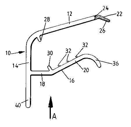
Figure 1 is an end view of a glazing panel end cap of the invention; and
Figure 2 is a view on arrow A of Figure 1.
Referring to the accompanying drawings, an end cap 10 for use on ends
of plastics glazing panels, especially ducted polycarbonate glazing panels,
comprises a channel section member having an upper side wall 12, a base 14
and a lower side wall 16. The end cap 10 is made by extruding PVC. The upper
side wall 12 extends from the base including an obtuse angle. The lower side
wall has a first part 18 extending normally to the base and a second part 20
converging towards the upper side wall.

CA 02516483 2005-08-17
WO 2004/079118 PCT/GB2004/000830
The upper side wall 12 has along its free edge a co-extruded gasket of
rubber or synthetic elastomeric material 22. The gasket material may, of
course,
be applied to the free edge of the upper side wall in any other suitable way,
such
as by bonding. The gasket has a first part 24 of similar thickness to the
upper
side wall and extending collinearly with the side wall and a second end part
26
angled downwards towards the lower side wall and narrowing in thickness
towards its free edge. The shaping of the gasket material is to ensure that,
when
the end cap is on a glazing panel, the gasket maintains sealing contact with
the
top surface of the glazing panel. Running along the inside of the end cap
where
the base and upper wall meet is a rib 23 that acts as a stop for a glazing
panel,
onto which the end cap has been pushed.
The lower side wall 16 of the end cap has on its inner face, where its first
and second parts meet a second rib 30 that also acts as a stop for a glazing
panel. The inside surFace of the second part of the lower side wall of the end
cap
has a series of gasket strips 32 co-extruded or otherwise bonded thereon. The
gasket strips 32 are angled towards the base of the end cap and provide grip
between the lower side wall and a glazing panel.
The lower side wall 16 has its free edge 36 curving away from the upper
side wall. That shaping of the .lower side wall facilitates pushing of the end
cap
onto a glazing panel. Also, the end cap side walls being of plastics material
will
have some inherent resilience that will allow them to diverge as a glazing
panel
is pushed into the end cap but will then exert clamping pressure on the
glazing
panel to hold the end cap in place and to improve the seals created by the
gasket material on the upper and the lower side walls.

CA 02516483 2005-08-17
WO 2004/079118 PCT/GB2004/000830
The base of the end cap continues below the lower side wall to provide a
foot 40.
As can be seen in Figure 2 of the drawings, the lower side wall 16 of the
end cap has a series of drainage holes 42 punched therein along its length.
The
holes 42 are mainly intended to allow any collected condensation to be drained
away.
In use, the end cap 10 is pushed onto the end of a polycarbonate glazing
panel. The curving of the lower side wall facilitates the insertion of the
glazing
panel past the gasket. The end cap is pushed on to the glazing panel until the
panel contacts the ribs 28 and 30. In the fitted position, the gasket 22 lies
on the
top surface of fihe panel to prevent passage of water into the end cap.
In forming a roof with glazing panels having end caps 10 fitted, the end
caps will be at the lower ends of the panels. because of the angle of the
upper
and lower side walls and the positions of the stops 28 and 30, the base of the
end cap will be substantially vertical. Any rainwater flowing down the roof
er~ill
drip off the end cap over a relatively narrow arc compared to a prior art end
cap.
Thus, gutters for such a roof can be made narrower and can be fitted further
under the roof edge, so becoming less obtrusive than hitherto.
As well as being usable for plastics glazing panels, the end caps of the
invention may also be used on roof panels of glass.

Representative Drawing
A single figure which represents the drawing illustrating the invention.
Administrative Status

2024-08-01:As part of the Next Generation Patents (NGP) transition, the Canadian Patents Database (CPD) now contains a more detailed Event History, which replicates the Event Log of our new back-office solution.

Please note that "Inactive:" events refers to events no longer in use in our new back-office solution.

For a clearer understanding of the status of the application/patent presented on this page, the site Disclaimer , as well as the definitions for Patent , Event History , Maintenance Fee  and Payment History  should be consulted.

Event History

Description Date
Application Not Reinstated by Deadline 2008-03-03
Time Limit for Reversal Expired 2008-03-03
Deemed Abandoned - Failure to Respond to Maintenance Fee Notice 2007-03-01
Letter Sent 2006-01-23
Inactive: Single transfer 2005-12-21
Inactive: Courtesy letter - Evidence 2005-10-25
Inactive: Cover page published 2005-10-19
Inactive: Notice - National entry - No RFE 2005-10-17
Application Received - PCT 2005-10-04
National Entry Requirements Determined Compliant 2005-08-17
Application Published (Open to Public Inspection) 2004-09-16

Abandonment History

Abandonment Date Reason Reinstatement Date
2007-03-01

Maintenance Fee

The last payment was received on 2005-08-17

Note : If the full payment has not been received on or before the date indicated, a further fee may be required which may be one of the following

  • the reinstatement fee;
  • the late payment fee; or
  • additional fee to reverse deemed expiry.

Please refer to the CIPO Patent Fees web page to see all current fee amounts.

Fee History

Fee Type Anniversary Year Due Date Paid Date
MF (application, 2nd anniv.) - standard 02 2006-03-01 2005-08-17
Registration of a document 2005-08-17
Basic national fee - standard 2005-08-17
Owners on Record

Note: Records showing the ownership history in alphabetical order.

Current Owners on Record
ULTRAFRAME (UK) LIMITED
Past Owners on Record
CHRISTOPHER RICHARDSON
Past Owners that do not appear in the "Owners on Record" listing will appear in other documentation within the application.
Documents

To view selected files, please enter reCAPTCHA code :


To view images, click a link in the Document Description column. To download the documents, select one or more checkboxes in the first column and then click the "Download Selected in PDF format (Zip Archive)" or the "Download Selected as Single PDF" button.

List of published and non-published patent-specific documents on the CPD .

If you have any difficulty accessing content, you can call the Client Service Centre at 1-866-997-1936 or send them an e-mail at CIPO Client Service Centre.


Document
Description 
Date
(yyyy-mm-dd) 
Number of pages   Size of Image (KB) 
Claims 2005-08-17 2 75
Description 2005-08-17 5 230
Representative drawing 2005-08-17 1 10
Abstract 2005-08-17 2 62
Drawings 2005-08-17 1 20
Cover Page 2005-10-19 1 34
Notice of National Entry 2005-10-17 1 192
Courtesy - Certificate of registration (related document(s)) 2006-01-23 1 104
Courtesy - Abandonment Letter (Maintenance Fee) 2007-04-26 1 174
PCT 2005-08-17 3 118
Correspondence 2005-10-17 1 25