Note: Descriptions are shown in the official language in which they were submitted.
CA 02516683 2009-03-23
APPARATUS AND METHOD FOR STABILIZING AN
EARTHEN EMBANKMENT
BACKGROUND OF THE INVENTION
The present invention relates to apparatus and methods for stabilizing earthen
retaining walls or embankments.
It is well known in the prior art to stabilize earthen embankments with
supports
and associated geogrids extending rearwardly from the support into the
stabilized
embankment. This includes embankments with a slope of less than 90 degrees and
embankments with a 90 degree slope. In cases where flexible fiber geogrids are
used, the
geogrid often is wrapped over the face of the support and under the floor of
the support.
But, the time and labor required to instal such geogrids is substantial.
Flexible fiber geogrids are available from various sources, for example,
Strata
Systems, Inc. of Cumming, Georgia, U.S.A. who provide a family of high
strength
polyester yarn geogrids for soil reinforcement.
U.S. Patent No. 5,975,810 (Taylor et al.) granted on November 2, 1999
discloses
apparatus for securing a flexible fiber geogrid to a support without wrapping
over the face
-1-
CA 02516683 2005-08-22
WO 2004/076751 PCT/CA2004/000254
of the support. In a number of embodiments there is a need to carefully fold
the forward
end portion of the geogrid back and forth in layers upon itself to provided
improved shear
strength. The layered end portion is then secured with a retaining rod which
is positioned
to press against the layers - in effect sandwiching the, layers between the
rod and the
underlying support on which the layers are positioned. In the field, the
required aligned
folds may be considered awkward and time consuming to achieve. Further, the
anchorage
does not have a positive hold on the geogrid. The integrity of the anchorage
when the
geogrid is tensioned appears to be largely dependent upon the compressive grip
which the
retaining rod imposes on the folded layers. In another embodiment, Taylor et
al. describe
anchoring a geogrid by means of a retaining rod around which the forward end
of a
geogrid is folded 180 degrees backwards. However, by itself, the rod does not
provide a
positive hold on the geogrid. The geogrid is restrained only by the resistance
of backfill
which is required to be placed over the folded end portion of the geogrid
before tension is
applied to the geogrid. The sufficiency of the restraint will be dependent on
the length of
the folded end portion and frictional characteristics of the baclJ'ill, the
latter of which may
vary depending on dampness and other factors. To adjust for such
considerations will
require particular skill and expertise on the part of those determining what
length a folded
portion should have to achieve a desired connection strength.
Accordingly, there is a need to provide apparatus and a method for positively
anchoring a flexible fiber geogrid to a support with a strong, reliable
connection which
requires minimal labor.
BRIEF SUMMARY OF THE INVENTION
In a broad aspect of the present invention, there is provided a structure for
stabilizing an earthen embankment which comprises an embankment support for
restraining movement of at least a part of the embankment, a flexible fiber
geogrid
extending longitudinally through the embankment from a first end portion
secured to the
-2-
CA 02516683 2009-03-23
support to a second end portion, and anchor means for securing one of the end
portions.
The anchor means comprises a pair of anchor rods spaced away from said
embankment
support and extending transversely in relation to the geogrid, and means for
limiting
movement of the anchor rods. The end portion secured by the anchor means is
wrapped
back and forth around the anchor rods so as to tighten thereon when the
geogrid is pulled
in longitudinal tension away from the anchor means.
In one embodiment, the embankment support comprises a retaining wall and the
means for limiting movement of the anchor rods comprises a plurality of anchor
bolts,
each bolt comprising a shaft extending from one end engaged with the wall to a
distal end
shaped to form an eyelet, one of the anchor rods extending through each of the
eyelets.
In another embodiment where the embankment support also comprises a retaining
wall, the earthen embankment lies between a rock face and the wall. The means
for
limiting movement of the anchor rods comprises a plurality of anchor bolts,
each bolt
comprising a shaft extending from one end engaged with the rock face to a
distal end
shaped to form an eyelet, one of the anchor rods extending through each of the
eyelets.
In a further embodiment, the embankment support of the stabilizing structure
comprises a floor section and a face section. The floor section extends
longitudinally
rearwardly from a forward end of the floor section to a rearward end and
includes at the
rearward end a plurality of transversely spaced hooking members. The face
section
extends upwardly from the forward end of the floor section to a top end of the
face section
at an angle corresponding to the slope of the embankment (i.e. up to 90
degrees). The
geogrid extends longitudinally rearwardly from the floor section and is
anchored thereto
by first and second anchor rods engaging the hooking members and extending
transverse
to the geogrid. Movement of the anchor rods relative to the support is limited
by the
hooking members when the geogrid is pulled in rearward longitudinal tension.
At least in
some circumstances, each hooking member preferably defines an inverted U-
shaped
envelope. In such cases, the geogrid preferably extends from a forward end of
the
geogrid:
-3-
CA 02516683 2005-08-22
WO 2004/076751 PCT/CA2004/000254
- first forwardly above the first anchor rod, preferably a cylindrical rod, to
a
position above the second anchor rod, also preferably a cylindrical rod;
- then wrappingly around the second anchor rod to a position below the second
anchor rod;
- then rearwardly to a position above the first anchor rod;
- then wrappingly around the first anchor rod to a position below the first
anchor
rod;
- then forwardly to a position below the second anchor rod;
- then wrappingly around the second anchor rod to a position above the second
anchor rod;
- then rearwardly above the first anchor rod and away from the support.
In another aspect of the present invention, there is provided a method of
anchoring
a flexible fiber geogrid to a support for stabilizing an earthen embankment,
the support
comprising an upwardly extending face section and a floor section e;itending
longitudinally reanvardly from the face section. The floor section comprises a
plurality of
transversely spaced hooking members, and the geogrid comprises longitudinally
extending webs sized and spaced to fit between the hooking members. The method
comprises:
- positioning a forward end portion of the geogrid atop the floor section such
that
the longitudinally extending webs of the geogrid extend between the hooking
members;
-4-
CA 02516683 2005-08-22
WO 2004/076751 PCT/CA2004/000254
- then positioning a first anchor rod atop the end portion of the geogrid
rearward
of the hooking members in a position where forward movement of the first
anchor rod is limited by the hooking members;
- then folding the end portion of the geogrid forwardly over the first anchor
rod;
- then positioning a second anchor rod atop the end portion of the geogrid
forward of the first anchor rod in a position where rearward movement of the
second anchor rod is limited by the hooking members;
- then folding the end portion and the geogrid rearwardly over the second
anchor
rod.
The foregoing structure and method enables a flexible fiber geogrid to be
anchored
to a support in a quick and efficient manner without imposing undesirable
stresses on the
geogrid when the geogrid is tensioned in relation to the suppor`i. Another key
point to
note is that unlilce the systems of Taylor et al. the strength of the
anchoring connection
(viz. the "pu11-out" factor) will proportionately increase as the longitudinal
tension applied
to the geogrid is increased. Further, since the anchoring connection of the
present
invention is not dependent on placing bacldill on the coiinection to provide
resistance, the
connection is necessarily independent of the quality of baclSill that
ultimately is added.
The frictional resistance which baclzfill may have to offer is immaterial to
the connection
strength.
The foregoing and other features and advantages of the present invention will
now
be described with reference to the drawings.
BRIEF DESCRIPTION OF THE DRAWINGS
FIG. 1 is a representational cross-section elevation view of a vertical
earthen
embankment stabilized by apparatus in accordance with the present invention.
-5-
CA 02516683 2005-08-22
WO 2004/076751 PCT/CA2004/000254
FIG. 2 is a representational cross-section elevation view of a sloped earthen
embankment stabilized by apparatus in accordance with the present invention.
FIG. 3 is a perspective view illustrating in more detail the linking of the
supports
shown in FIG. 1. Similar linking is present between the supports shown in FIG.
2.
FIG. 4 is a cross-section elevation view illustrating in more detail the
anchoring of
a flexible fiber geogrid to an embankment support in accordance with the
present
invention.
FIGS. 5 through 10 are a stepwise progression of perspective views showing a
method of achieving the anchoring illustrated in FIG. 4.
FIG. 11 is a cross-section elevation view illustrating a backfill earthen
embanlcnent contained between a retaining wall and a rock face with geogrids
eictending
therebetween, an end portion of each of the geogrids being anchored to the
rock face with
apparatus in accordance with the present invention.
FIG. 12 is a cross-section elevation view illustrating in more detail the
manner
whereby the geogrids shown in FIG. 11 are anchored to the ro& face sliown in
FIG. 11.
FIG. 13 is a cross-section elevation view illustrating a backfill earthen
embankment stabilized by a retaining wall and geogrids, the geogrids being
anchored to
the retaining wall with apparatus in accordance with the present invention.
FIG. 14 is a perspective view of an alternative embanl;snent support.
FIG. 15 is a cross-section elevation view illustrating the anchoring of a
flexible
fiber geogrid to the embankment support shown in FIG. 14.
-6-
CA 02516683 2005-08-22
WO 2004/076751 PCT/CA2004/000254
DETAILED DESCRIPTIC}N OF PREFERRED EIVlBODIMENTS
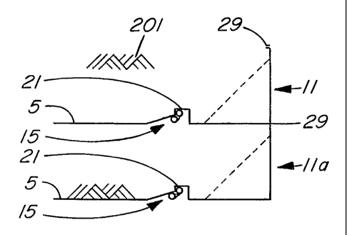
FIGS. 1 and 2 illustrate flexible fiber geogrids"5 anchored to embankment
supports
generally designated 11, l la, 12, 12a. In FIG. 1, geogrids 5 and supports 11,
1la serve to
stabilize a vertical earthen embankment of backfill 201: In FIG. 2, geogrids 5
and
supports 12,12a serve to stabilize a sloped earthen embankment of backfill
202.
Geogrids 5 are anchored to support 11 or 12, as the case may be, by a
preferred
anchoring mechanism which is generally designated 15 and which is described
below in
more detail with reference to FIG. 4-10. Each geogrid 5 comprises a plurality
of spaced
elongated tension nzembers 6 extending from a forward end 7 and intersected at
spaced
intervals by a plurality of transverse members 8. For strength, geogrids 5
preferably are
fabricated from high density polyester material.
FIG. 3 illustrates the structure of supports 11, l la in more detail. Note
that
geogrids 5 and bac1ffil1201 have not been included in FIG. 3 so as not to
obscure the
structure.
Support 11 comprises a plurality of transversely spaced elongated steel wire
members 20, each elaending longitudinally from a liooked rearward end or
hooking
member 21 (which defines an inverted U-shaped envelope) to a forward end 25,
then
upwardly to a hooked upper end 29. The lowermost horizontally extending
portion of
wire members 20 together define a floor section of the support. Similarly, the
forwardmost upwardly extending portion of wire meinbers 20 together define a
face
section of support 11 which extends upwardly at 90 degrees relative to the
floor section.
Support 11 also includes transversely extending steel wire crossbars, namely:
rearward crossbar 31, intermediate crossbar 32 on the floor section, forward
crossbar 33
extending proximate forward ends 25 of wire members 20, and upper crossbar 34.
Each
of such crossbars are welded to wire members 20 at their points of
intersection therewith
-7-
CA 02516683 2005-08-22
WO 2004/076751 PCT/CA2004/000254
to hold wire members 20 in their parallel spaced relationship. As well, to
provide added
strength, support 11 includes a plurality of diagonal wire braces 40 each of
which is
hooked at its lower end to intermediate crossbar 32 and at its upper end to
upper crossbar
34.
The construction of support 1 la is substantially the same as that of support
11.
During the process of stabilizing an embankment, support 11a of course will be
installed
first with its geogrid 5 anchored to the support (in the manner described
below). Then,
embankment backfill sufficient to provide a base for support 11 will be added
over the
floor section and rearwardly of support 1 la while leaving hooked upper ends
29 of
support 11a free to engage forward crossbar 33 of support 11.
As can be seen in FIG. 3, forward crossbar 33 of support 11 is engaged by
hooked
upper ends 29 of support 11a. The hooked upper ends 29 of support 11 are free
ends but
may be used to engage the upper crossbar of yet another similar support (not
shown)
positioned above the level of support 11. This may be repeated for several
levels or tiers
of supports and not merely the two levels depicted in FIGS. 1 and 3.
The only substantive difference between supports 11, 11a and supports 12, 12a,
is
that the face section of the latter extends upwardly and rearwardly at an
angle of less than
90 degrees relative to the floor section, and is thus suitable for a sloped
embankment
extending at the same angle. Depending on the job at hand, it will be
understood that
supports like supports 11, 11a, 12, 12a may be combined in the same project.
For
example, in FIG. 3, support 11 or support 11a could be replaced by a support
like support
12 or with a support having some other angle between its face and floor
sections.
Apart from the provision of hooked upper ends 29, the construction of supports
11,
11a, 12, 12a is considered to be prior art. The advantage provided by hooked
upper ends
29 is to enable supports on successive levels to be quickly linked in the
manner shown in
-8-
CA 02516683 2005-08-22
WO 2004/076751 PCT/CA2004/000254
FIG. 3 as construction of a stabilized embankment proceeds and, as each new
support is
added to the structure, to enable its associated geogrid to be anchored to the
support and
then tensioned while the support is held in position by the support to which
it is linked.
Each geogrid 5 is anchored to support 11, l la, 12, 12a, as the case may be,
by first
and second anchor rods (preferably cylindrical rods 55, 60): see FIGS. 4-10
for the
example of support 11. When a geogrid 5 is fully anchored to support 11 as
shown in
FIG. 4, each rod 55, 60 extends transverse to the geogrid. Rod 55 is
positioned rearward
of rod 60 outside the inverted U-shaped envelope defined by end 21 and rod 60
is
positioned forward of rod 55 within the envelope. As seen in FIG. 4, geogrid 5
extends
from its forward end'7
- first forwardly above rods 55 and 60 to a position above rod 60;
- then wrappingly around rod 60 to a position below rod 60;
- then rearwardly to a position above rod 55;
- then wrappingly around rod 55 to a position below rod 55;
- then forwardly to a position below rod 60;
- then wrappingly around rod 60 to a position above rod 60;
- tlien rearwardly above rod 55 and distantly away from support 11.
When longitudinal tension is applied to geogrid 5 in the direction of arrow
100
(FIG. 4) while support 11 is held in position the geogrid tightens on the
rods; rod 55 is
pulled by the geogrid forwardly against the rearward side of leg 22 of end 21;
and rod 60
is pulled by the geogrid rearwardly against the forward side of leg 22. Thus,
both forward
movement of rod 55 and rearward movement of rod 60 are limited by leg 22.
-9-
CA 02516683 2005-08-22
WO 2004/076751 PCT/CA2004/000254
It will be note that upward movement of rod 60 is limited because it is
contained
within the inverted U-shaped envelope defined by end 21. This is advantageous
because
when a worker pulls on the geogrid before rods 55, 60 are drawn to the final
positions
shown in FIG. 4, rod 60 may otherwise slip up and away from its anchoring
position if the
manual pulling force includes an upward component relative to support 11.
Reference is now made to FIGS. 5 through 10 which illustrate a stepwise
progression of steps for anchoring geogrid 5 to support 11. As shown in FIG.
5, a forward
portion of geogrid 5 is first positioned above support 11 with its forward end
7 directed
rearwardly. The forward portion is then lowered in the direction of arrow 101
(FIG. 5) to
the position shown in FIG. 6 where the longitudinal tension members 6 of
geogrid 5 fall
between hooking members 21. Although not illustrated, it may be noted that the
portion
of geogrid 5 not shown in FIG. 5 typically will be rolled up in a form easy to
be unrolled.
Next, anchoring rod 55 is located from a position above geogrid 5 as shown in
FIG. 6 to a position atop geogrid 5 as shown in FIG. 6(viz. in the direction
of arrow 102).
Then, the forward portion of geogrid 5 as shown in FIG. 6 is folded forwardly
over rod 55
to the position shown in FIG. 7(viz. in the direction of arrow 103).
Next, as indicated in FIGS. 7 and 8, anchoring rod 60 is transversely inserted
atop
the forwardly folded end portion of geogrid 5 and through the inverted U-
shaped
envelopes provided by ends 21 of support 11.
Next, as indicated in FIGS. 9 and 10 by arrows 104 and 105, both the forward
portion and the remaining extension of geogrid 5 are folded rearwardly over
anchoring rod
60 to the position shown in FIG. 10. Geogrid 5 is then situated to be
tensioned to the
position shown in FIG. 4 where it is tighened on rods 55, 60.
Other structures for supporting earthen embankments are within the scope of
the
present invention. For example, FIG. 11 illustrates a case where a backfill
earthen
-10-
CA 02516683 2005-08-22
WO 2004/076751 PCT/CA2004/000254
embankment 205 lies between a retaining wall 70 comprised of concrete blocks
72 and a
rock face 300. Flexible fiber geogrids 80 progressively installed during the
process of
adding the backfill each extend longitudinally through embankment 205 from a
first end
portion 81 held and secured between adjacent blocks 72 to a second end portion
82
secured by a pair of anchor rods 83, 84 extending transversely in relation to
the geodgrid
and anchor bolts 85. Only one anchor bolt 85 for each geogrid 80 is visible in
FIG. 11,
but it will be understood that a number of such bolts will be used for a given
geogrid
depending on the width of the geogrid and the load to be carried by the bolts.
As best seen in FIG. 12, each bolt 85 comprises a shaft 86 extending from one
end
engaged (e.g. by threading) with rock face 300 to a distal end shaped to form
an eyelet 87.
Rod 83 extends longitudinally through eyelet 87 and bears against the inside
lower right
quadrant thereof. Rod 84 bears against shaft 86 and the outside lower right
quadrant of
eyelet 87. Bolt 85 thereby limits movenient of rods 83, 84. In much the same
manner as
shown in FIG. 5 where the forward end of geogrid 5 is wrapped back and forth
around
anchor rods 55, 60, end 82 of geogrid 80 is wrapped back and forth around
anchor rods
83, 84 so as to tighten on the rods when geogrid 80 is pulled in longitudinal
tension.
(Typically, each geogrid 80 v,rill be pulled and held in tension during
construction when its
end portion 81 is being secured between adjacent blocks 72.
As another example, FIG. 13 illustrates a case where a backfill earthen
embankment 210 is stabilized by a solid concrete retaining wall generally
designated 90.
Flexible fiber geogrids 92 progressively installed during the process of
adding the backfill
extend from wall 90 into embankment 210. An end portion 94 of each geogrid is
anchored to wall 90 by means of anchor rods 83, 84 and anchor bolts 85, the
latter of
which are engaged with wall 90 rather than a rock face as in the case of the
embodiment
shown in FIG. 11. Since the anchoring mechanism is otherwise essentially the
same as
-11-
CA 02516683 2005-08-22
WO 2004/076751 PCT/CA2004/000254
the anchoring mechanism described in relation to FIGS. 11-12, it will not be
described
here in any further detail.
As a further example, it should be noted that embankment supports like support
11
can be used but without hooked rearward ends 21. While considered preferable,
such
hooked ends are not considered essential. More particularly, FIG. 14 shows an
embankment support 111 which is similar in construction to support 11, but
with a
plurality of transversely spaced elongated steel wire members 120 instead of
wire
members 20. In the floor section of support 111, wire members 120 have
straight
rearward ends rather than hooked rearward ends 21. Crossbar 31 extends across
the top of
the straight rearward ends. FIG. 15 shows the manner whereby a geogrid 5 is
anchored to
the rearward end of the floor section of support 111 by wrapping the geogrid
back and
forth around anchor rods 55, 60. Rod 55 abuts against crossbar 31 and against
the tops of
wire members 120. Rod 60 abuts against the bottoms of wire members 120.
Movement
of the rods 55, 60 is tllereby limited.
Further Variations
A variety of modifications, chagiges and variation: to the invention are
possible
within the spirit and scope of the following claims, and will undoubtedly
occur to those
slcilled in the art. The invention should not be considered as restricted to
the specific
embodiments that have been described and illustrated with reference to the
drawings. In
the claims, means-plus-function clauses are intended to cover the structures
described
herein as performing the recited function and not only structural equivalents
but also
equivalent structures.
-12-