Note: Descriptions are shown in the official language in which they were submitted.
CA 02516734 2005-08-19
WO 2004/073754 PCT/GB2004/000672
1
A DEVICE FOR STERILISING A FLUID
The present invention relates to a device for sterilising
a fluid, in particular to a device for sterilising a fluid
using ultraviolet radiation.
It is well known that bacteria and other micro-organisms
can be killed by the use of electromagnetic radiation such as
ultraviolet radiation. In particular, ultraviolet radiation
may be used to sterilise a source of water by passing the
water near to a source of ultraviolet radiation for a
sufficient time for any micro-organisms to be killed. It is
also known to use this process in a batch or a continuous
manner.
One particular use of such water sterilisation devices
is to sterilise the water for use in a shower. Because of
their nature, showers can produce a fine mist which may be
inhaled by the user of the shower. If the water is infected
with the legionella bacteria this can have potentially fatal
results. Some prior art devices contain ultraviolet sources
1'U wlii~_.~li are perio~ll~~ally turi~mcl ~~ff if n~~ water is flowiru~. if
the water begins to flow before the ultraviolet source reaches
optimum performance, there is a danger of micro-organisms
flowing past the ultraviolet source without being killed.
To address this problem, some prior art devices have a
delaying mechanism whereby flow of water is delayed until the
ultraviolet source reaches optimum performance. However,~this
may lead to a user, unaware of this delaying mechanism,
thinking that the water supply is faulty and leaving the
shower or tap left open. This may lead to unwanted flooding.
Other prior art systems use ultraviolet radiation to
sterilise a fluid some distance upstream of the point of exit
of the fluid from the system. If the fluid is flowing slowly,
or periodically stops flowing, there is the danger of harmful
microorganisms being introduced into the fluid downstream of
the ultraviolet radiation source. These systems cannot
CA 02516734 2005-08-19
WO 2004/073754 PCT/GB2004/000672
2
provide a sterilised source of fluid under these conditions.
It is therefore apparent that there exists a need for an
improved device for sterilising a fluid.
According to one aspect of the present invention there
is provided a device for sterilising a fluid comprising a
sterilisation zone having an outlet portion comprising at
least one aperture through which the fluid may exit the
device, wherein the sterilisation zone is arranged to be
irradiated by a source of ultraviolet radiation such that
substantially all of the internal surfaces of the outlet
portion are directly irradiated by the source of ultraviolet
radiation and wherein the source of ultraviolet radiation and
the at least one aperture are arranged such that substantially
no ultraviolet radiation may be transmitted directly from the
source of ultraviolet radiation through the at least one
aperture.
Preferably, the outlet portion defines an elongate volume
extending away from the source of ultraviolet radiation.
Conveniently, the at least one aperture leads to an open
~U aii .space.
Advantageously, the outlet portion extends continuously
to the source of ultraviolet radiation.
Preferably, the outlet portion comprises a shower head.
Conveniently, the device further comprises a casing which
prevents removal of the shower head.
Advantageously, the outlet portion comprises a tap.
Preferably, the device comprises stainless steel.
Conveniently, the source of ultraviolet radiation is an
ultraviolet lamp.
Advantageously, the source of ultraviolet radiation is
contained within a quartz housing.
Preferably, the device has a substantially tubular
configuration with the source of ultraviolet radiation
positioned substantially along the longitudinal axis of the
device.
CA 02516734 2005-08-19
WO 2004/073754 PCT/GB2004/000672
3
Conveniently, the device is positioned in use with the
outlet portion projecting at least partly upwardly from the
remainder of the device.
Advantageously, the device is arranged such that the
source of ultraviolet radiation is shut off if the device is
opened.
Preferably, the device comprises means to shut off the
flow of fluid if the source of ultraviolet radiation is off.
Conveniently, the means to shut off the flow of fluid
comprises a pulse latching valve.
Advantageously, the means to shut off the flow of fluid
is powered by a capacitor.
Preferably, the device further comprises means to prevent
flow of fluid through the device for a predetermined period
of time after the source of ultraviolet radiation is
activated.
Embodiments of the present invention will now be
described, by way of example, with reference to the
accompanying drawings in whichv
U Fi~~urc 1 is a cross-section of a device according to the
present invention,
Figure 2 is a cross-section of an alternative embodiment
of a device according to the invention,
Figure 3 is a partial cross-section of the outlet of a
device of the invention,
Figure 4 is a perspective view of a further embodiment
of the invention, and;
Figure 5 is a perspective view of the embodiment shown
in figure 4 with its casing in an open position.
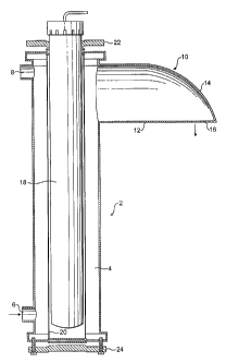
Turning to Figure 1, a device according to the invention
is shown generally at 2, having a substantially tubular
configuration. Although the device 2 is described herein with
reference to a unit to provide sterile water for a shower, it
is to be appreciated that other embodiments are possible. For
example, the devices of the invention are applicable to a wide
CA 02516734 2005-08-19
WO 2004/073754 PCT/GB2004/000672
4
range of fluids, including gases and liquids other than water.
Also, although a shower unit is described, the invention is
also applicable to fluid outlets such as'basin or bath taps.
Thus the present invention has a wide range of applications
such as use in medical, consumer and food related environments
such as hotels and hospitals.
The device 2 comprises an elongate chamber 4 bounded by
a substantially cylindrical wall. In use, the device 2 is
positioned in a substantially vertical configuration, as
explained below.
Towards the lower end of the chamber 4 there is located
an inlet 6 for the passage of water into the chamber 4.
Towards the top end of the chamber 4 there is located an
opening 8, the purpose of which will be described below.
Towards the top end of the chamber 4 there is also located an
outlet 10 having a substantially tubular configuration which
projects and tapers away from the chamber 4. The outlet 10
has a lower wall 12 which extends in a substantially straight
line away from the chamber 4. The outlet 10 has an upper wall
~'l7 14 wl'~i~~ri curVa~ ~~1~::~wt1 tc~ meet the 1«wer wall 1.'. A i~~~i~mi a1
the lower wall 12 is provided with awumber of apertures 16,
thus forming a shower rose.
A tubular ultraviolet (UV) lamp 18 is located
substantially centrally along the longitudinal axis of the
chamber 4. The UV lamp 18 is located within a concentric
cylindrical quartz sleeve 20. Liquid-tight fittings 22 and
24 are located at the ends of the chamber 4 to locate the
quartz sleeve 20 and the UV lamp 18 within the chamber 4 in
a liquid-tight manner.
As mentioned above, there is an outlet 8 positioned
towards the upper end of chamber 4. Outlet 8 leads to a
sensor which detects whether the UV lamp 18 is turned on or
off.
Water may enter the device 2 through inlet 6 and pass
into the annular space in chamber 4 around the quartz sleeve
CA 02516734 2005-08-19
WO 2004/073754 PCT/GB2004/000672
20. The water flows up and around the quartz sleeve 20, being
irradiated by the UV lamp 18. The water then flows through
the outlet 10 and passes out of the device 2 through the
apertures 16. The device 2 thus provides a spray of water in
5 a similar way to a traditional shower.
Whilst water is flowing, the device 2 is arranged such
that any micro-organisms present in the water are irradiated
with enough ultraviolet radiation in order to kill them. The
device 2 shown has a UV lamp 18 with a power of 15W and could
safely sterilise a flow of water of up to 8 litres/minute.
In use, the device 2 typically provides a maximum flow of
around 6 litres/minute. If the sensor located at outlet 8
detects that the UV lamp 18 is turned off, it activates a
valve which shuts off the water supply to inlet 6. Thus, the
passage of water through the device 2 whilst the ultraviolet
lamp 18 is turned off is prevented ensuring that only sterile
water leaves the apertures 16.
There are also means for detecting the opening of the
chamber 4, for example by unscrewing the outlet 10 from the
~01 Uaall ~~f tlm ~~:liamt~ei 4. It it i~~ detent~~d that tl-m ~:liarilb~r
is opened, the valve again shuts off the water supply to the
device 2 to prevent any unwanted exposure to the UV radiation.
The outlet 10 is shaped and located relative to the UV
lamp 18 such that substantially all of the inner surfaces of
outlet 10 are directly irradiated by the UV lamp 18. Thus,
the device 2 ensures that both the water and the surfaces over
which it flows right up until the point of exit of the device
2 are irradiated and thus sterile.
It-is to be appreciated that other configurations of the
device are possible which still achieve the same result. The
important feature is for the device to be arranged such that
substantially all of the internal surfaces of the outlet
portion of the device are irradiated by the ultraviolet
source, right up to the point of exit of the fluid from the
device.
CA 02516734 2005-08-19
WO 2004/073754 PCT/GB2004/000672
6
Also, the UV lamp 18 is normally left switched on in
order to maintain a sterile environment within the chamber 4
of the outlet 10. Thus, a user may shut off the water flowing
through the device 2 whilst not in use, with UV lamp 18
remaining turned on. This has the advantage of prolonging the
life of the UV lamp, which is degraded by intermittent use.
Also, the constant irradiation of the inner surfaces of the
device 2 whilst the water is not flowing prevents
contamination by killing any microorganisms which may enter
the device. Furthermore, because the UV lamp 18 is already
on and at optimum performance, there is no need to delay the
flow of water. Thus the disadvantages of such a delay are
avoided. .
It is to be appreciated however that an alternative
embodiment may be provided in which the lamp 18 is activated
only when there is a flow of water. This embodiment would
benefit from the complete sterilisation of the inner surfaces
of the device up to the point of exit of the water.
As ultraviolet light may be harmful to the user of the
U ~:~rvi~~e ~~ the ~~utlet 10 is arranged such that substantiall~i
no UV radiation is directly transmitted from the UV lamp 18
through the apertures 16 to leave the device 2. In other
words, it is not possible to directly view the UV lamp 18
through the apertures 16.
When there is no flow of water, the device 2 is
maintained full of water. The apertures 16 and the outlet 10
are arranged to minimise egress of water through the aperture
16 under these conditions.
Figure 2 shows an alternative embodiment of the
invention. Device 26 comprises a tubular chamber 28' having
an inlet 30 and an outlet 32. In this embodiment the outlet
32 projects outwardly and upwardly from the annular chamber
28. Apertures 34 are located on the lower surface of outlet
32 towards the end thereof. This has the advantage of
minimising the pressure of the water located within the outlet
CA 02516734 2005-08-19
WO 2004/073754 PCT/GB2004/000672
7
32 in the vicinity of the apertures 34 whilst water is not
flowing through the device 26. Thus the chances of liquid
being lost through the apertures 34 whilst liquid,is not
flowing through the device are reduced. The embodiment shown
has an outlet 32 with a substantially horizontal upper wall
36. As indicated, the upper wall 36 is positioned slightly
below the highest point of the chamber 28. This results in
a small head of pressure in the outlet 32 ensuring that the
outlet remains full of water. In alternative embodiments, the
outlet could project higher than the highest point of the
chamber.
Figure 3 is a large-scale view of the top portion of the
device 26 shown in figure 2. As discussed above, the lamp 18
directly illuminates substantially all of the internal
surfaces of the outlet 32, without UV radiation escaping
directly through the apertures 34. In the embodiment shown,
this result is achieved simply by the size and position of the
apertures 34 relative to the lamp 18 and the thickness of the
wall of the outlet 32.
~'c~ Line 3J illustrates the path ~f ~.1~ r,~~~i,atiun fram a point
on the lamp 38 substantially horizontally into the outlet 32.
As shown, although the path 38 enters an aperture 34, it
terminates on the inner wall of that aperture distal to the
lamp 18. Thus UV radiation along path 38 cannot directly pass
out of the device 26 through the apertures 34.
Line 40 illustrates the path from the highest possible
point of lamp 40 to the apertures 34. Even though the path
40 is angled more steeply into the apertures 34 than path 38,
the path 40 still terminates on the inner surface of an
aperture. Thus light from the lamp 18 travelling on path 40
cannot directly escape through the apertures 34.
Path 42 shows the minimum angle needed for light to
directly pass through the apertures 34. It can be seen that
a user of the device cannot see through the apertures 34 to
see the lamp 18.
CA 02516734 2005-08-19
WO 2004/073754 PCT/GB2004/000672
8
Although the invention has been described with reference
to outlets having an integral shower rose, it is to be
appreciated that outlets with detachable or removable shower
'roses are also possible. In such cases, the device is
preferably arranged so that there is no direct optical path
to the lamp from outside the device even if the shower rose
is removed.
Also, as mentioned above, the invention is applicable to
fluid outlets in general, including basin taps. Ln some
circumstances, a sterilisation unit for a basin may be
arranged with an outlet towards the bottom of the device.
Whilst water (or other fluids) are not flowing through such
a device, there would exist a larger pressure at the outlet
than with the arrangements shown in the accompanying figures.
Whilst the device is preferably arranged to retain a full body
of water in such circumstances, further means for preventing
water loss may be required. Such means may, for example,
reduce the pressure inside the device using techniques
apparent to those skilled in the art. It is preferable to
~'0 azj~~i~:l rowvif~g p~iLs in ~.:~rclei to minimise rnanufa~~tuie and
services costs and to avoid possible non-sterile portions
within such a device.
Figure 4 shows a further embodiment of the invention
comprising a wall-mounted shower unit 44. The unit 44 has a
35 plastic casing 46 through which protrudes a shower rose 48.
A flexible water inlet hose 50 is connected to the base of the
unit 44 using a snap fit connector 52. On the front face of
the casing 46 there is a clear window 54.
Figure 5 shows the unit 44 with the front casing 46
30 hinged open. The components of the device 44 comprise a
sterilisation tube 56 containing a UV lamp. The tube 56 has
an outlet portion 58 projecting therefrom which terminates in
the shower rose 48. The casing 46 has an aperture through
which the shower rose 48 projects when~the casing 46 is in a
35 closed position. The shower rose 48 is attached to the outlet
CA 02516734 2005-08-19
WO 2004/073754 PCT/GB2004/000672
9
portion 58 in such a way as to prevent the removal of the rose
48 whilst the casing 46 is closed. The casing 46 must be
opened before the rose 48 can be removed. As will be
described below, this prevents the accidental exposure of a
user to UV radiation by the unit. A control unit 60 comprises
electronic~components which control the functioning of the
unit. On the control unit 60 there is provided a sensor 62
which detects whether the casing 46 is opened or closed. When
the casing 46 is opened, the sensor 62 is activated and the
UV lamp is automatically switched off.
There is a water inlet pipe 72 leading from the connector
52 to the base of the sterilisation tube 56. The inlet pipe
72 is provided with a shut-off valve 74 which is controlled
by the control unit 60. When the switch 62 is activated by
the opening of the casing 46, the control unit 60 activates
the valve 74 to shut off the flow of liquid through the
device. This prevents potentially unsterilised liquid from
leaving the device 44. Preferably, the valve 74 is a pulse
latching valve which operates via a magnetic pulse. The valve
n ~I4 is aestivated l~~y a capacitor. Thus, in the event of power
failure, the capacitor powers the valve 74, allowing it to
close, again preventing the flow of potentially unsterilised
water through unit 44.
When the casing 46 is opened without the electrical power
to the device being turned off, the warning light 68 is
activated to warn the user of this fact.
When the device is initially switched on, the red
indicator light 64 is activated to indicated that the unit is
powered but not yet operational. The control unit 60
activates the UV lamp in the sterilisation tube 56 but
prevents water from flowing through the unit for a
predetermined period of two minutes. Depending on the
circumstances, other periods of time could be used. This
,delay is provided to allow the UV lamp to reach optimum
working conditions and to give sufficient time for the
CA 02516734 2005-08-19
WO 2004/073754 PCT/GB2004/000672
sterilisation of the water already contained within the unit.
Once the predetermined period of time ends, the red light 64
is turned off and the green light 66 is turned on to show that
normal operating conditions have been reached. The control
5 unit 60 then opens the valve 74, allowing water to flow
through the device.
There is also provided a photosensor 70 which detects the
emission of UV. radiation from the UV lamp within the
sterilisation tube 5'6. If the lamp fails or if the level of
10 radiation has dropped below a predetermined safe minimum
value, the control unit 60 closes the valve 74 and turns off
the UV lamp. The red light 64 is then turned on in a flashing
mode to alert the user of the situation. The UV lamp can then
be replaced or repaired in order for the unit to become
operational again.
Under certain circumstances, a user may wish to rinse a
fitting such as a bath. In order to do so, the flexible hose
50 may be disconnected via the connector 52 from the unit 44
and used to rinse such a fitting. As micro-organisms such as
~'i~ le~~i~~nell~ are ric~imally ~:~nly h,~irnful when piesent irr ~i mi~L
or aerosol of water droplets, the use of a water hose in this
way should not pose any risk.
It is to be appreciated that the water inlet for the unit
44 could be provided at the back of the device. Thus, the
user would be presented with only the unit 44 mounted on a
wall without any visible external water connections.
Other embodiments are possible where the bulk of the unit
is located within a cavity behind a wall or other such
configurations such that only the water outlet or shower rose
is visible. Also, the device, or parts thereof, may be
constructed from materials other than stainless steel,
including metals such as copper and plastics such as ABS,
nylon and u-PVC.