Note: Descriptions are shown in the official language in which they were submitted.
CA 02517111 2005-08-26
1 "Drilling Rig Floor Drainage System"
2 Inventor: Gerald Lesko
3 FIELD OF THE INVENTION
4 The present invention relates to the field of drainage systems for drilling
rigs.
More specifically, the present invention relates to a system for collecting
fluids, such
6 as drilling fluid, spilt onto the drilling rig floor when sections of
drilling pipe are
7 removed from the drill string.
8 BACKGROUND OF THE INVENTION
9 Generally, drilling rigs consists of a pit, or area of ground beneath the
rig,
surrounding the drill pipe, which terminates in a wellhead. When sections of
drilling
11 pipe are removed or "tripped out" from the drill string during drilling
operations, the
12 column of drilling fluid contained in the pipe section spills onto the
drilling rig floor.
13 These fluids over the edges of the drilling rig floor and fall into the
pit. The spilt
14 fluids are not only a safety hazard for the workers on the rig site, they
can be an
environmental hazard depending on the composition of the fluids themselves.
For
16 this reason, drainage systems are needed on drilling rigs to collect
drilling fluid spilt
17 onto the rig floor to improve the safety of the rig floor for the workers
and to collect
18 the fluids before they reach the ground so that they can be recycled or
properly
19 disposed of.
US Patent no. 5,228,506 teaches a spill collection system associated with a
21 well drilling rig or a work-over rig, and the wellhead of a borehole. The
system is
22 supported from the wellhead itself, and consists of a removable impervious
system
23 with four flexible open-faced panels circumferentially arranged around an
apertured
24 plate member. Such an open-faced system still allows for some liquid
traveling at
{E5077853.DOC;1 }
CA 02517111 2005-08-26
2
1 high speed to deflect off the panel surface and spill or spray over on to
the ground,
2 rather than gravitating towards the apertured plate member. This system is
not
3 permanently affixed to the rig and requires assembly and disassembly each
time it is
4 to be used at the rig site.
US Patent no. 5,343,943 teaches a waste fluid containment and recovery
6 apparatus for installation in-line with a piping system. The system can be
combined
7 with a portable base for transportation, and a hydraulic lift whereby
vertical height of
8 the system can be adjusted. Such a system can provide a grate floor to
prevent spray-
9 off of drilling fluid spilling on to the system, and to provide a gripping
surface for
workmen walking on the floor, but is wanting in its ability to collect spilt
drilling
11 fluid.
12 US Patent no. 5,634,485 teaches a method and apparatus for retrofitting
13 existing drilling rigs with a catch pan, but the system fails to provide a
platform upon
14 which drill workers may walk safely above the catch pan. The system is also
permanently affixed in place and is unable to be moved vertically or rotatably
with the
16 drill pipe.
17 It is, therefore, desirable to have a drainage system that can safely and
18 efficiently collect drilling fluid that is spilled during the drilling and
servicing of a
19 well.
SUMMARY OF THE INVENTION
21 The present invention is a drainage system that is designed for use on a
22 drilling rig and is capable of collecting drilling fluid spilt during
drilling and servicing
23 processes. When the drainage system is assembled and in position around the
drill
24 pipe, drilling fluid waste may drain through a grid floor into a collection
trough
{E5077853.DOC; l }
CA 02517111 2007-11-26
3
1 underneath, and may then be then guided away from the rig for recycling or
proper
2 disposal. This system may help to ensure the safety of those walking on the
grid floor
3 by preventing slipping on the spilled drilling fluid, and may prevent
contamination of
4 the soil surrounding the drill rig resulting from spilled drilling fluid.
The present invention comprises a drilling floor surface that forms at least a
6 portion of the drilling rig floor. The drilling floor surface can be of any
suitable shape
7 but is, preferably, rectangular. A plurality of openings are disposed about
the drilling
8 floor surface that allow fluids to drain through. In one embodiment, the
openings are
9 sized and positioned whereby the openings are separated from one another by
at least
a portion of the drilling floor surface. Located underneath the drilling floor
surface is
11 a trough to collect fluids that drain through the openings. The trough
guides the fluids
12 to an outlet aperture. The openings may be located anywhere on the drilling
floor
13 surface but are, preferably, disposed at least partially about the
perimeter of the
14 drilling floor surface. Accordingly, the trough is located underneath the
openings.
The trough slopes downwardly towards the outlet aperture so that fluids will
naturally
16 flow towards the outlet aperture due to gravity.
17 In a preferred embodiment of the present invention, the drilling floor
surface,
18 the trough and the outlet aperture are components of a structure or module
that may
19 be removably mounted on a drilling rig. The module consists of a top panel
comprising the drilling floor surface and a substructure comprising a bottom
surface
21 and four sidewalls extending between the top panel and the bottom surface
to form a
22 six-sided structure. In this embodiment, the outlet aperture extends
through a sidewall
23 of the module to connect to an external drainage pipe, hose or trough to
guide the
24 fluids away from the drilling rig floor.
It is an object of the present invention to provide a safe and efficient
drainage
26 system for drilling rigs in the oil industry.
{E5377039.DOC;1 }
CA 02517111 2007-11-26
4
1 It is another object of the present invention to provide effective removal
of
2 drilling fluid from a drilling rig, thereby preventing contamination of the
soil beneath
3 the drilling rig.
4 It is yet another object of the present invention to provide a safer
environment
for oil rig workers working on the drilling rig floor.
6 Broadly stated, the present invention is a drainage system for draining
fluids
7 from a drilling rig floor of a drilling rig, comprising a substantially
horizontal drilling
8 floor surface suitable for use as a drilling rig floor, said floor surface
defining at least
9 a portion of said drilling rig floor; a trough disposed underneath said
drilling floor
surface; a plurality of drainage openings disposed on said drilling floor
surface, said
11 openings located above said trough whereby fluids on said drilling floor
surface are
12 able to drain through said openings into said trough, said openings
separated from one
13 another by at least a portion of said drilling rig floor surface; and an
outlet aperture
14 operatively attached to said trough, the combination of said trough and
said aperture
adapted to guide said fluids away from said drilling rig floor.
16 BRIEF DESCRIPTION OF THE DRAWINGS
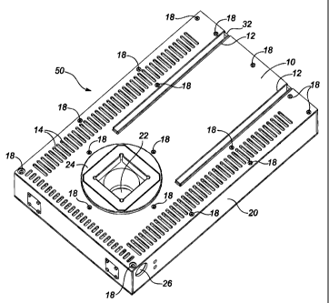
17 Figure 1 is an isometric view of the present invention.
18 Figure 2 is an isometric exploded view of the present invention.
19 Figure 3 is an isometric view of the present invention with the top panel
of the
module removed.
21 Figure 4 is a perspective view of the present invention mounted on a
drilling
22 rig.
23 DETAILED DESCRIPTION OF THE PREFERRED EMBODIMENT
24 The present invention is illustrated in Figures 1 to 4. Referring to
Figures 1
and 2, module 50 of the present invention comprises of top panel 10 mounted on
{E5377039. DOC; I }
CA 02517111 2007-11-26
1 substructure 20. Top panel 10 is secured to substructure 20 with bolts
passing
2 through boltholes 18 and comprises opening 16 to allow rotary table 24 to
pass
3 through. Top panel 10 further comprises drainage slots 14 placed around its
4 perimeter. Slots 14 are sized and positioned on top panel 10 whereby slots
14 are
5 separated from one another by at least a portion of top panel 10.
6 Referring to Figures 2 and 3, substructure 20 is shown having rotary table
24
7 and slots 32. It should be obvious to those skilled in the art that module
50 does not
8 require rotary table 24 if a top-drive unit (not shown) is used to operate
the drill string
9 which passes through opening 22. Slots 32 provide an opening that lead to a
guide
track (not shown) for a robotic roughneck (not shown) that travels to and from
rotary
11 table 24 along slots 32. Located about at least a portion of the perimeter
of
12 substructure 20 is trough 28. Trough 28 is positioned within substructure
20 such that
13 trough 28 lies underneath drainage slots 14. Trough 28 slopes downwardly
from one
14 end of substructure 20 to an opposite end to intersect with outlet aperture
26. Outlet
aperture 26 extends through a sidewall of substructure 20 to connect with a
drain pipe,
16 hose or trough (not shown) which, in turn, leads to a collection pit or
vessel (not
17 shown). It should be obvious to those skilled in the art that trough 28 can
slope
18 downwardly towards either the front or the rear of module 50. In the
embodiment of
19 the present invention shown in this specification, trough 28 slopes towards
the rotary
table end of module 50 to connect with outlet aperture 26.
21 Referring to Figure 4, module 50 is shown mounted on drilling rig 40 such
22 that top panel 10 is flush with drilling rig floor 30. In operation,
drilling fluid
23 draining from sections of pipe tripped out of the drill string spill on
module 50 and
24 drain through drainage slots 14 to trough 28. Trough 28 guides the fluid
towards
{E5377039. DOC;1 }
CA 02517111 2005-08-26
6
1 outlet aperture 26 where the fluid is then guided to a collection pit or
vessel where the
2 fluid can be recycled or properly disposed of.
3 Although a preferred embodiment has been shown and described, it will be
4 appreciated by those skilled in the art that various changes and
modifications might be
made without departing from the scope of the invention. The terms and
expressions
6 used in the preceding specification have been used herein as terms of
description and
7 not of limitation, and there is no intention in the use of such terms and
expressions of
8 excluding equivalents of the features shown and described or portions
thereof, it being
9 recognized at the scope of the invention as defined and limited only by the
claims that
follow.
11
12
{E5077853.DOC;1 }