Note: Descriptions are shown in the official language in which they were submitted.
CA 02517122 2005-08-24
WO 2004/088295 PCT/NL2004/000150
METHOD AND SYSTEM FOR INSPECTING PACKAGINGS
Methods and systems have recently been developed for
inspecting packagings such as drink-containing bottles.
The occurrence of for instance glass splinters in beer
can result in corporate losses as a result of for
instance rejected batches, return operations and damage
to the company reputation because the presence of glass
splinters will be the subject of negative press reports.
From the international patent application
PCT/NL96/00049, which is deemed as interpolated herein by
means of reference, is known a method and apparatus for
detecting extremely small glass splinters in filled beer
bottles. Each filled bottle is herein rotated for a short
time in a separate station and then brought quickly to a
standstill,. whereby movements of the small glass
splinters can be detected using a light source-camera
system and associated image processing.
This method functions well enough in practice but
requires a complex apparatus in the filling line of a
brewery or soft drink manufacturer. Carrying out an
inspection using such a method takes on average about 2.1
seconds per bottle. Such a system is moreover expensive
because, in order to achieve the high average speed of
for instance 60,000 bottles per hour of a filling line, a
plurality of rotation and image recording stations is
required, for instance 36.
So as to improve the above stated method, the
present invention provides a method for inspecting
packagings for a liquid product, such as drinks,
comprising steps for:
- setting a packaging into rotation,
- irradiating the packaging during the rotation with
a radiation of a predetermined wavelength,
1
CA 02517122 2005-08-24
WO 2004/088295 PCT/NL2004/000150
- making at least one series of at least two
recordings of at least a part of the content of the
packaging during the rotation, this with an image
recording device suitable for making recordings at the
predetermined wavelength.
A method according to the present invention has the
advantage that a good inspection is achieved in a shorter
time per packaging, whereby a relatively small number of
rotation and image recording stations (detection units,
inspection units) is required. When an embodiment
according to the present invention is applied, an
inspection takes an average of 0.7 second per bottle. One
result hereof is that inspection systems can be realized
more easily and more cheaply by applying the method.
A system with a smaller number of rotation and image
recording stations, for instance 12-24, will suffice to
perform an embodiment of a method according to the
present invention.
In a further embodiment the packaging is situated in
substantially the same rotational position relative to
the recording device during successive recordings of the
series. Successive images are made of a bottle revolving
on its vertical axis. During rotation of the bottle at
least 1 x an image is recorded of the (continuously
revolving) bottle. These images are stored. Each image is
compared to a preceding or subsequent image of therefore
the same bottle with 360 rotation difference. When these
two successive images are compared, the bottle will be
situated in the same position while a piece of glass
possibly present in the bottle will however have another
position in the image. This glass displacement between
the two images can be detected, for instance by
subtracting the images from each other. If anything
remains in the image, then glass is present. Subtracting
2.
CA 02517122 2005-08-24
WO 2004/088295 PCT/NL2004/000150
the images from each other is a per se known principle
which is applied inter alia in the inspection of labels.
A bottle with a glass particle will be detected.
It is possible to already carry out the inspection
during the rotation (when the bottle is revolving and the
glass is moving in relation to the bottle). The spin and
inspection can in principle be carried out together in
about 0.7 second, whereby for instance only 18 (12-24)
inspection units are required to realize a capacity of
60,000 bottles per hour.
According to a further embodiment successive
recordings of the series are made with an intervening
time interval of a predetermined duration. A relatively
simple method of activating the camera for the purpose of
taking a picture hereby becomes possible.
The rotation speed is preferably varied during the
period in which the recordings of a series are made. A
difference between the speed of the content of the
packaging and the packaging is hereby realized.
There is further a preferred embodiment wherein the
rotation direction is varied during the period in which
the recordings of a series are made. Changes in speed
enhance the effect of the difference in speed.
It is advantageous to make a plurality of recordings
from a different angle of view in relation to the
packaging. It hereby becomes possible for instance to
detect particles in packagings on which labels have
already been arranged.
Image information from the images of a series is
preferably compared in order to detect the presence of
undesired particles, such as glass particles, in the
packaging.
3
CA 02517122 2005-08-24
WO 2004/088295 PCT/NL2004/000150
A further aspect of the present invention relates to
a system for performing a method as claimed in one or
more of the foregoing claims.
Further advantages, features and details of the
present invention will be elucidated on the basis of the
following description of preferred embodiments thereof,
with reference to the annexed drawing, in which:
- fig. 1 shows a schematic view of an inspection
station according to the present invention;
- fig. 2 shows a time diagram of a recording
schedule according to an embodiment of the present
invention;
- fig. 3 shows a time diagram according to the
embodiment of fig. 2;
- fig. 4-8 show a time diagram of different
embodiments according to the present invention;
- fig. 9-12 show a diagrammatic view of further
embodiments according to the invention.
One beer bottle B at a time (fig. 1) is clamped in a
detection unit 12 between a ring 1 and a head 2. A motor
3, which is coupled to head 2 via a speed-reducing
mechanism 4 and an optional brake 5, serves to set the
bottle into rotation. Ring 1 and head 2 are therefore
mounted rotatably relative to a frame 6. Light from a
light source 7 is further cast into the bottle and
recordings are made of the content of the bottle. Because
there are differences in the rotation speed of the bottle
and the liquid in the bottle owing to mass inertia, the
content will move relative to the bottle. If recordings
are now made at different moments using a CCD camera 8,
the content will be situated relative to the bottle at a
position other than the bottle in successive recordings.
Use is made of this to detect for instance glass
particles.
4
CA 02517122 2005-08-24
WO 2004/088295 PCT/NL2004/000150
The detection unit further comprises an activation
signal generating unit, (e.g. a laser trigger) for
creating a signal on the basis of which a camera 8 makes
a picture. A laser transmitter/detection unit 16 emits a
laser beam 17 in the direction of a reflector 15 on a
rotating part of the detection unit. If the reflector
passes through the laser beam, this latter is reflected
and the reflected beam is received by detection unit 16.
A signal is then sent to the camera on which a picture is
taken.
An alternative hereto is that the motor generates a
position signal to the camera, on the basis of which this
latter takes a picture.
The image information is processed in computer 10
and can be displayed on screen 11.
In addition to the above described advantages,
embodiments described hereinbelow have the further
advantages compared to the prior art that:
- inspection can take place directly during rotation
of the bottle,
- the bottle does not have to be physically stopped
and held still,
- the bottle can be inspected from a number of sides
instead of from one side, thereby increasing the
reliability of inspection,
- fouling behind a label, (heavy) scuffing,
embossing or pre-printed bottle can be detected,
- the machine can be placed after the labelling
device, whereby flexible line lay-outs are possible and
the machine can be placed as last in the line, and a real
final inspection is therefore possible,
- there is less mechanical complexity, whereby the
mechanical reliability and availability of the machine
(OPI) improves,
5
CA 02517122 2005-08-24
WO 2004/088295 PCT/NL2004/000150
- because the inspection units are individually
controlled, an optimal spin profile can be implemented
per inspection unit,
- in the case of a line stoppage all bottles present
in the carrousel can be inspected, whereby in the case of
a line stoppage there are no uninspected bottles (which
result in product loss and waste).
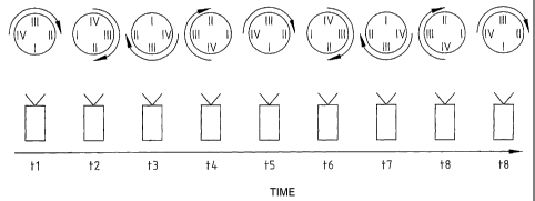
In addition to recording a series of images
consisting of one picture per rotation, it is also
possible to record a plurality of images per rotation
(for instance at 0°, 90°, 180° and 270° or more
(fig. 2)
with view I, II, III, and IV respectively). Images which
are recorded at a determined angle are then compared to a
subsequent image recorded 360 after this determined
angle. This is shown in the following time diagram (N. B.
in top view: the bottle rotates about its vertical axis
but is otherwise stationary relative to the camera):
On the basis of this time diagram the following
table is compiled for the case that recordings of 4
images per rotation are made, in which is indicated which
part of the bottle is being shown at a particular moment
in time:
image ( t 1 ) I
image (t2) IT
image (t3) III
image (t4) IV
image (t5) I
image (t6) II
image (t7) III
image (t8) IV
image (t9) I
etc.
6
CA 02517122 2005-08-24
WO 2004/088295 PCT/NL2004/000150
Herefrom is made the following table which indicates
at what times a particular part of the bottle is being
shown. If no movement is detected between the two
successive images of the same particular part of the
bottle, no glass or contamination has been found.
Pictures can be taken at for instance the following
points in time:
I t1, t5, t9, t13, etc.
II t2, t6, t10, t14, etc.
III t3, t7, t11, t15, etc.
IV t4, t8, t12, t16, etc.
The movement of the glass relative to the bottle is
realized as follows (fig. 3):
When the bottle undergoes an angular displacement, the
liquid in the bottle will come into motion more slowly
than the bottle. The (glass) particle (G) in the liquid
therefore comes into motion more slowly than the bottle.
The position of the (glass) particle compared in two
images (with substantially 360 difference in bottle
rotation relative to each other) will change when the
rotation speed of the bottle is increased.
When the rotation speed of the bottle is decreased,
the liquid in the bottle will rotate more rapidly after a
time than the bottle. The (glass) particle in the liquid
will then also rotate more rapidly than the bottle. The
position of the (glass) particle compared in two images
(with substantially 360 difference in bottle rotation
relative to each other) will change when the rotation
speed of the bottle is decreased in similar manner as
stated when the rotation speed is increased.
As addition to the above method of generating
relative movement, use can also be made of the period
CA 02517122 2005-08-24
WO 2004/088295 PCT/NL2004/000150
immediately after start-up of the bottle rotation. At
that moment the (glass) particle will, owing to the
inertia of movement, still be at rest while the bottle is
already moving. At this stage, which preferably lasts
about 0-0.3 sec., with a correct choice of exposure and
camera shutter time the bottle will be shown out of focus
and the (glass) particle will be shown sharply in focus
or moving very slowly. The (glass) particle can be
detected by applying per se known image processing
techniques.
It will be apparent that it is also possible with
this method to inspect a larger or smaller number of
parts of the bottle. The advantage compared to other
methods, including the patent (WO 97/14956) is that the
bottle is inspected from a plurality of sides, whereby
the chance of detection is increased (or the inspection
time can be shortened while the chance of detection
remains the same). This advantage is of particular
importance in the case of pre-labelled bottles and
scuffed bottles.
In order to enable recording of the above series of
images the use of asynchronous reset cameras is to be
recommended. These are cameras activated (triggered) by
an external signal to start the recording of an image. In
this application this can take place by using a position
feedback signal coming from a detection unit.
The rotation pattern can be adjusted with this
method such that an optimal movement is achieved during
recording of images, and thereby detection of possible
particles (fig. 4). The concept of rotation profile is
important for this purpose. The rotation profile shows
the angular speed of the bottle on its vertical axis as a
function of time. A simple example is:
t0 - tl: start-up
8
CA 02517122 2005-08-24
WO 2004/088295 PCT/NL2004/000150
t1 - t2: continuous rotation
t2 - t3: braking
It is possible with the method to record and process
images during the whole period t0 to t3.
It is particularly advantageous to continue varying
the angular speed (fig. 5) because the particle then
remains moving continuously in relation to the bottle.
Also possible are more complex (for instance reverse
rotation) or very short rotation profiles (fig. 6, 7).
Very short inspection times can hereby be realized, which
can result in a very compact machine. An optimal rotation
profile (fig. 8) can also be set for specific products,
for instance syrup.
Integration with other, already existing inspections
which are carried out in practice on a bottle is made
possible by this method of camera per detection unit with
separately controlled motor:
- 360 Label inspection making use of bottle rotation,
- Side wall inspection of decorated and embossed bottles,
and for instance
- Foil detection.
A number of cameras in the fixed world can further
be used for further inspections wherein the bottles are
oriented.
Data communication can be minimized by linking motor
control and image recording triggering by means of
intelligent control.
Image series allocation to different PCs can be
realized by means of for instance the Firewire protocol
(IEEE 1394 standard) or by fast PCs or by multiplexer
technology.
The relative movement of the (glass) particle to be
detected in the two images, with 360 difference, in
relation to the rotating bottle must be great such that
9
CA 02517122 2005-08-24
WO 2004/088295 PCT/NL2004/000150
software detection through movement detection is possible
(because position of glass particle changes).
In a further embodiment the image recording is
carried out at a regular time interval and at unknown
angular displacement (synchronous reset camera) instead
of at an unknown moment and regular angular displacement
of the bottle (asynchronous reset camera): The advantage
hereof is a simple camera activation. It is more
complicated here that the recorded images of a series can
be/are of different sides of the bottle, whereby owing to
the visible differences between the sides subtraction
images will not be black even if (glass) particles are
not present. With a good dark field illumination the
orientation of the bottle is not important because the
side, and therefore also the differences between the
sides, will then not be visible in the image (black image
- black image = black image). If the dark field
illumination is not.perfect, it is possible by means of
image processing techniques to distinguish reflections
from (glass) particles.
Further embodiments according to the present
invention comprise:
- a carrousel with between 12-24 detection units.
Such a carrousel can be placed in per se known manner in
a filling line for bottles. A further variant is a
detection line with for instance fixed cameras, wherein
the bottles advance one after another during the
detection in per se known manner;
- bottle orientation feedback means per detection
unit (for controlling the moment of camera triggering);
- a drive unit per detection unit (e.g. stepping or
servo motor with position feedback). One drive can
optionally be used for all detection units;
- a camera per detection unit;
CA 02517122 2005-08-24
WO 2004/088295 PCT/NL2004/000150
- image field for the images for recording not only
on the underside of bottle but now also on the whole
bottle for the purpose of inspecting foils and detecting
floating objects;
- (Firewire) IR camera 80 frames/sec or more;
- Infrared illuminator with (modified) dark
field illumination;
- colour cameras for inspecting labels, caps, and/or
filling level of bottles;
- image processing computers (IPPs) and
communication computers (COMMPC);
- optical slip ring for video and other data
transfer;
- hardware for industrial environment: camera,
illuminator, system housing, IPP PC, COMMPC. This means
being in accordance with for instance IP65.
In figures 9-12 several embodiments are shown for
arranging camera and illumination positions with respect
to each other and/or the bottle to be examined. In figure
9, a bottle B that is placed in the rotation head 30 is
rotated as described in the above. The bottles is
illuminated by means of the lamp or radiation means 32
through the bottom of the bottle.
In figure 10 the bottle is illuminated from the
sides by means of lights 34 and 35. The camera is
positioned under the bottom of the bottle for taking
images. In figure 11 the arrangement of figure 10 is
altered in that the camera is placed at an angle with
respect to the heart line of the.bottle. Advantages of
these embodiments are that the whole bottom area is
recorded in a recording. A result hereof is that e.g. a
glass particle can be spotted quicker and in several
subsequent recordings. The inspection time can therefore
be reduced. A further advantage is that when a process is
11
CA 02517122 2005-08-24
WO 2004/088295 PCT/NL2004/000150
used in which the bottle is dried before inspection,
merely the bottom needs to be dried because the
recordings are taken from below. Such drying of the
bottom can be performed by means of quickly spinning the
bottle, which spinning is advantageously performed for
the detection process. Furthermore, an advantage of the
skewed angle of the camera in fig. 11 is that the
recording is performed at an angle with respect to the
rim of the head which means that detection in the utmost
lower part of the bottom area in the bottle can more
fully be performed. Also less dirt is likely to fall on
the camera as it is positioned sideways with respect to
the bottle.
A further advantageous embodiment (fig. 12)
comprises two lamps 34 radiating into the bottle from the
sides and a prism 42 with three sides 39,40,41 for
reflecting light. Also mirrors 44 are arranged in this
embodiment for reflecting light. In this arrangement the
light from the bottle can be detected by the camera from
two sides, thereby improving the amount of information
from the bottom area of the bottle that is recorded by
the camera. In such an embodiment also 2 cameras can be
deployed for capturing image data reflecting form the
prism, or capturing the light directly from the mirrors.
The possibility of e.g. a glass particle falling in the
'shadow' of the head 30 is thereby diminished.
Also, as depicted in schematic 13, a camera can be
placed at an angle above the bottom area of the bottle,
e.g. having vision through the shoulder of the bottle.
The taking of image recordings can e.g. be triggered
by the orientation of the bottle or at a predetermined or
a random time interval. The orientation of the bottle can
in the first case e.g. be determined by means of a
sensor.
12
CA 02517122 2005-08-24
WO 2004/088295 PCT/NL2004/000150
The processing of the recorded images can be handled
in several ways. Images with a substantially identical
bottle orientation can be mutually subtracted and the
difference image can be analysed with respect to residual
information. Alternatively, the recorded image can be
analysed with respect to an earlier recorded image by
time shifting or back rotating towards the bottle
orientation/position of the earlier recorded image and
subsequently further processing thereof by means of e.g.
the subtraction process. Also, a trajectory cam be
determined and described of particles recorded on several
images. Based on parameters of the trajectory the nature
of the particle can be determined as being e.g. glass,
which would lead to a bottle, reject, or organic material,
which would lead to an accepted bottle.
Different embodiments described in the foregoing can
be freely combined. The rights sought are defined by the
appended claims.
13