Note: Descriptions are shown in the official language in which they were submitted.
CA 02517541 2005-08-29
Shapiro Cohen No. 1731PO1CA01
POCKET PAGER PROTECTOR
FIELD OF THE INVENTION
The present invention relates to enclosures for
wireless devices such as pagers and in particular to hinged
waterproof enclosures for such wireless devices.
BACKGROUND TO THE INVENTION
In hospitals and long-term care facilities
("facility"), there has always been a need for a means of
communication between a patient's bedside and the nursing
care personnel ("nurse") charged with the care and
supervision of the patient. In the past, such communication
was necessarily effected by means of hard-wired connection
between the patient's bedside and the nursing care station.
Because the intervening space is typically in a high traffic
area, this hard-wired connection frequently had to be routed
behind walls and through overhead ducts, which generally
entailed considerable installation expense and effort, and
was not conducive to upgrade and/or repair.
The advent of wireless telecommunications devices
such as pagers has significantly reduced the need for such
hard-wired connections, at a reduced cost and resulting in
simpler installation and repair, while permitting greater
flexibility to the nurses. At the patient bed-side, the
call button may be connected (through the telephone system
or otherwise) to a transmitter that is programmed to
generate a page to a specific and unique telephone number.
Such telephone number is associated with a
wireless pager, so that a call from the patient's bedside
CA 02517541 2005-08-29
- 2 -
Shapiro Cohen No. 1731POlCAO1
(patient call) may be communicated to the pager
automatically. As with most pager systems, the receipt of a
patient call may be communicated audibly, by a visual cue
such as a flashing indicator and/or in tactile fashion such
as by a vibrating signal. The nurse may manipulate the
display of messages and otherwise control the management of
the pager by applying pressure to one or more buttons on the
face of the pager, or optionally, by applying pressure on
designated points of a touch screen display on the pager.
Additionally, the transmitter may optionally be
configured to provide certain information, such as the date
and time of day, the identification of the patient and/or
room and/or bed number and may even be configured to permit
a brief text or voice message to communicate the reason for
the patient call. More sophisticated systems may permit
multiple patient calls, for example from a common ward or
floor, to be routed to a single pager, or alternatively, for
more than one pager to receive a given patient call.
One of the great advantages afforded by such a
wireless system is the portability of the pager. With hard-
wired connection systems, the patient call may only be
received at the nursing care station, where the receiver is
located. In a long-term care and/or hospital facility, the
nurses are generally required to travel throughout the
facility, in order to deal with patients and their needs.
Thus, it is likely that there may be a significant
percentage of time that the appropriate nurse is not present
at the nursing care station when a patient call is made.
Thus, delays in processing the patient call are inherent in
such systems.
CA 02517541 2005-08-29
- 3
Shapiro Cohen No. 1731PO1CA01
With a pager-based system, the pager may be held
or worn by a designated nurse having responsibility for the
patient wherever he or she may be, so that the delay in
receiving the patient call is obviated. The range of such
pagers is such that the designated nurse may be anywhere
within the facility and still receive the patient call.
However, the portability of the pager poses new
problems. Typically, the work of nurses requires extension
and a large degree of movement. They usually carry one or
more objects in their hands and may travel in a hurry and
through cramped spaces. Thus, it is not uncommon for pagers
to be clipped to uniforms. Despite this precaution, there
is a significant possibility that the pager will be dropped.
The problem is compounded by the fact that nurses
frequently operate in proximity to water, whether in the
form of a therapeutic swimming pool, a bathtub, toilet, sink
or bedpan or a spill. Additionally, the nurses are
frequently covered in other fluids, such as beverages or
even blood and other bodily fluids. If such fluids come
into contact with the pager, the delicate electronic
circuitry could be irreparably affected.
As well, most facilities eschew the use of
carpeting on their floor surfaces for a number of reasons,
including issues of hygiene. As a result, in such
facilities, the floor surfaces are often hard and bare, such
as concrete or hardwood. Thus, the facility tends to be a
harsh environment from the point of view of the pagers worn
by the nurses.
CA 02517541 2005-08-29
4 -
Shapiro Cohen No. 1731PO1CAO1
Because the pagers have a significant per-unit
cost, and because the nature of their application requires
specific programming and mandates that they remain in
operating condition, the cost of a broken pager due to
dropping and/or water damage is considerable.
Moreover, as nurses go on and off-shift, it is not
uncommon to forget to transfer over equipment used during
the shift. In most cases, the equipment is personal to the
nurse, or else can be easily substituted when such an
omission occurs. However, in the case of the patient call
pagers, such an occurrence could have significant
deleterious effects. For example, a patient could initiate
an urgent patient call, which would only be received by an
off-duty nurse, and conceivably a considerable distance away
from the facility.
Furthermore, as nurses regularly change wards and
areas of responsibility, the portability of pagers may
result in improper distribution of the pagers at any given
time, again with potentially disastrous consequences.
A number of attempts have been made to provide
enclosures for pocket pagers that are water- and/or shock-
resistant.
United States Patent No. 6,031,524 issued February
29, 2002 to Kunert discloses a complicated user-replaceable
component assembly, which permits replacement of components
and devices such as portable electronic devices. An
environmental seal is provided around the components to
protect the inner circuitry of the electronic device.
Shock-resistant mounting of the display panel beneath the
CA 02517541 2005-08-29
-
Shapiro Cohen No. 1731POlCA01
keypad and accommodation for the electric connection between
the keypad and the portable electronic device's inner
circuitry is provided. However, Kunert requires the
provision of a keypad on the enclosure, which is
5 electrically connected to and substitutes for the keypad of
the portable electronic device.
United States Patent No. 6,646,864 issued November
11, 2003 to Richardson discloses a protective case for an
electronic device that has a touch screen. The touch screen
is protected with a membrane adapted to the specific contour
and profile of the electronic device and allows the user to
use a touch screen interface with no shortcomings. The
protective case is further adapted to allow infra-red and
other communication signals while the device is secured
inside the case. Further, electrical connections can be
made through the case without affecting the protection
afforded the electronic device inside. The enclosure is in
the form of a hinged clamshell device with external ribs
that prevent torsional stresses thereon and internal foam
inserts for shock-relief. Keypad and touch screen input may
be through a sheet of thin plastic disposed within an
opening in the enclosure and sealed in water-resistant
fashion by the interposition of an O-ring between it and the
enclosure opening. Thus, in assembling the enclosure, a
number of components must be maintained in position
simultaneously, which may be problematic, especially in a
high-traffic environment such as at a facility.
United States Patent No. 6,659,274 issued December
9, 2003 to Enners discloses a container for a PDA comprising
a three dimensional enclosure open at one end and through
CA 02517541 2005-08-29
6 -
Shapiro Cohen No. 1731POlCA01
which the PDA can be inserted. A clear rubber screen is
positioned over the touch screen of the PDA, to provide
touch point access thereto. The opening in the enclosure
can be capped by a cover having an O-ring across an internal
projection, which matingly engages with the open end of the
cover to provide a water-resistant seal. The rubber screen
is integral with or permanently affixed to the enclosure,
which provides significant difficulties in construction and
precludes the replacement of the screen in the event of a
tear or rupture. As well, the use of clear rubber would
appear to significantly increase the cost of construction.
Furthermore, the material may not be highly conducive to
accurate data entry therethrough, or to visibility of the
visual outputs of the pager.
United States Patent No. 6,068,119 issued May 30,
2000 to Derr et al discloses a waterproof protective device
for holding an apparatus having an interaction field formed
from a dimensionally stable protective housing having lower
and upper housing parts. The two parts are releasably
hingedly connected together and an inside contour of the
protective housing is adapted and constructed to closely
receive the apparatus with approximately no play. The
protective housing is provided with a transparent
elastically flexible operating area of reduced wall
thickness to enable an interaction field to be viewed and
manipulated while encased within the enclosure. A seal is
provided between the two parts in the form of a mating
circumferential groove and rim, one or both of which may be
provided with lips. Derr et al's apparatus renders it
awkward to insert the pager into and remove the pager from
CA 02517541 2005-08-29
7 -
Shapiro Cohen No. 1731POlCA01
the enclosure. A separate pusher must be used to urge the
pager out of the enclosure.
United States Patent No. 4,836,256 issued June 6,
1989 to Meliconi discloses a shock-proof protective sheath
for television remote controls, which comprises a hollow
container and holder element, embodied in shock proof
material that substantially matches and hugs the external
profile of the appliance it encompasses. It is provided
with at least two openings, one of which affords access to
the remote control's push buttons and the other of which
allows passage of the controlled pulses. The window on the
front of the sheath, corresponding to the push buttons of
the remote control is covered by a thin plastic material,
welded or affixed by adhesive strip to the edges of the
opening in the sheath, which allows buttons to be pressed
while maintaining water tightness. Again, the permanent
attachment of the window within the sheath increases the
difficulty and cost of construction and precludes easy
replacement of the screen in the event of a tear or a
rupture.
United States Patent No. 4,901,852 issued February
20, 1990 to King discloses a protective cover for pagers
comprising a film of transparent stretchable material (e.g.
595HC silicon plastic) formed to cover the top, four sides
and at least a portion of the bottom of a pager. The cover
includes accordion-type pleats, which are positioned to
reside adjacent switches, a belt clip and the like, to allow
operation thereof. While some modicum of watertightness may
be provided, subject to the size and positioning of openings
CA 02517541 2005-08-29
8 -
Shapiro Cohen No. 1731PO1CAO1
in the enclosure, King's enclosure provides no means of
shock-resistance.
United States Design Patent No. D455,730 issued
April 16, 2002 to Hakim-Nelson discloses a case of a certain
dimension adapted to fit the pager, constructed of an
entirely transparent material Protrusions are provided to
accommodate push buttons. Access to the enclosure is
through a removable door. Again, there appears to be only
minimal shock-resistance to Hakim-Nelson's enclosure.
Finally, PCT International Application No.
PCT/FI03/00434 published December 11, 2003 in the name of
Bordi discloses a case where an electronic device includes a
watertight and at least partly transparent case body
substantially corresponding to the shape of the electronic
device, the case being open at one end, as well as the lid
watertightly closing the open end of the case body. It also
includes an annular intermediate part on which both the case
body and the lid are supported and to which they can be
latched. The case body includes an annular supporting
surface and the lid includes an annular pressure contact
area, so that when closing the lid, the sealing flange is
pressed in between the supporting surface and the pressure
contact area thereby closing the space defined by the lid
and the case body.
SUMMARY OF THE INVENTION
Accordingly, it is desirable to provide an
enclosure for a pocket pager that is water-resistant. It is
further desirable to provide an enclosure for a pocket pager
that is shock-resistant.
CA 02517541 2005-08-29
9 -
Shapiro Cohen No. 1731POICAO1
Still further, it is desirable to provide an
enclosure that nevertheless permits the user to conveniently
receive the visual, audible and/or tactile outputs of the
pager and to provide inputs to the pager while in the
enclosure.
Moreover, it is desirable to provide an enclosure
that permits easy removal of the pager for maintenance and
other purposes.
It is also desirable to provide a means for
automatically ensuring that the pager does not inadvertently
leave the designated facility. Moreover, it is desirable to
provide a means whereby the region with which a particular
pager is to be associated can be easily and quickly
identified.
Finally, it is desirable to provide such a
mechanism at a low cost and with ease of manufacture and
simplicity of construction and of assembly and capable of
easy and inexpensive repair of broken or ruptured
components.
The present invention accomplishes these aims by
providing a pager enclosure that comprises an open-topped
bottom container that is padded with foam adhesive inserts,
a removable transparent film that spans the top of the
container and is supported by the foam inserts and an
annular cover that is removably hinged to the container and
can be quickly affixed thereto to seal the film to the
container. Optionally, the container can be fitted with an
RFID or other passive identification device to identify if
CA 02517541 2005-08-29
- 10 -
Shapiro Cohen No. 1731PO1CAO1
the enclosed pager is being transported outside the facility
and to trigger an indication to this effect.
The cover is fitted with an integral and removable
hinge assembly that fits into a slot in the container and
that permits the enclosure to be easily opened to insert and
remove a pager therefrom. The cover may be constructed of
anodized aluminum and coloured to provide visual feedback as
to the ward or wing with which it is associated. The cover
also provides a means for attachment to the body of the
user, such as by an extendible clip.
A plurality of screws extend through the cover to
fix it through the film and to the bottom container.
According to a broad aspect of an embodiment of
the present invention, there is disclosed an enclosure for a
wireless device having visual outputs and capable of
accepting and processing pressure inputs comprising:
a) a bottom portion with an open top;
b) reinforcements along the bottom portion, the
reinforced bottom portion being adapted to accept
and enclose the wireless device in a snug fit and
to cushion the wireless device from shock;
c) a flexible, tear-resistant transparent film
capable of accepting and transmitting pressure
inputs to the wireless device, the film being
supportable by the reinforcements of the bottom
portion and adapted to completely cover the
wireless device and the bottom portion at the top
thereof;
CA 02517541 2010-02-05
Shapiro Cohen No. 1731POlCA01
d) a removable cover adapted to press the film against
the reinforcements to produce a water-resistant
seal about the wireless device;
e) a removable hinge assembly adapted to releasably
attach the cover to the bottom portion in hinged
engagement; and
f) fixing elements to secure the cover portion about
the film and bottom portion.
The invention seeks to provide an enclosure for a
wireless device having visual outputs and capable of
accepting and processing pressure inputs, the enclosure
comprising:
(a) a bottom portion with an open top and comprising a base,
a pair of opposing side walls and a pair of opposing end
walls, each said wall having a substantially planar upper
end surface;
(b) reinforcements secured within the bottom portion and
substantially adjacent to each said wall, and constructed
and arranged to receive and releasably secure the wireless
device in a snug fit and to cushion the wireless device from
shock, said reinforcements each having an upper
reinforcement surface, said upper reinforcement surfaces
together substantially forming a common plane with the upper
end surfaces of said walls;
(c) a flexible, tear-resistant transparent film capable of
accepting and transmitting pressure inputs to the wireless
device, the film being configured to extend over and cover
the common plane and be supported by the reinforcements and
said walls and to completely cover the wireless device;
CA 02517541 2010-02-05
Shapiro Cohen No. 1731P01CA01
11a -
(d) a removable cover having a lower surface adapted to
press the film against the reinforcements and said walls to
produce a water-resistant seal about the wireless device;
(e) a removable hinge assembly adapted to releasably attach
the cover to the bottom portion in hinged engagement;" and
(f) fixing elements to secure the cover portion about the
film and bottom portion.
BRIEF DESCRIPTION OF THE DRAWINGS
The embodiments of the present invention will now
be described by reference to the following figures, in which
identical reference numerals in different figures indicate
identical elements and in which:
Figure 1 is a perspective view of the enclosure in
accordance with an embodiment of the invention, in use, with
the cover in the open position;
Figure 2 is an exploded perspective view of the
enclosure of Figure 1; and
Figure 2A is a partial exploded perspective view
of the bottom container and foam strips of the enclosure of
Figure 1.
Figure 3 is an exploded perspective view seen from
the bottom of the enclosure of Figure 1.
DETAILED DESCRIPTION OF THE PREFERRED EMBODIMENTS
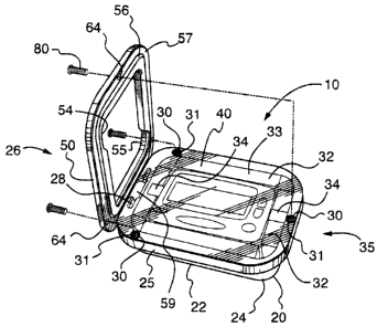
Referring to Figures 1 to 4, there is shown an
enclosure generally at 10, comprising an open-topped bottom
CA 02517541 2005-08-29
- 12 -
Shapiro Cohen No. 1731PO1CA01
container 20, a removable plastic film 40, a removably-
hinged cover 50, a hinge pin 70 (Figure 3) and a plurality
of machine screws 80 (Figure 3).
The bottom container 20 is preferably injection
molded out of a suitable thermoplastic such as an acetal
copolymer plastic such as is manufactured under the Trade-
mark DELRIN. Alternatively, it could be machined out of a
light metal, such as aluminum.
The interior dimensions of the bottom container 20
are sized to accommodate and completely surround a pager in
a loose fit. In a preferred exemplary embodiment for use
with a Commtech model No. 6120 pager, the outer dimensions
of the bottom container may be 3.573" long by 2.539" wide by
0.955" high.
The bottom container 20 has a thickened bottom 21
and side 22 and end walls 23. Preferably, the thickness of
all three structures is the same. A thickness of 0.059" has
been found to be suitable in the above-described exemplary
embodiment and is provided by way of example only. The
thickened structures 21, 22, 23 provide a measure of shock
absorbency in and of themselves.
Both the interior and exterior surfaces of these
structures 21, 22, 23 intersect in rounded edges and corners
24, so as to minimize the potential for breakage and stress
diffusion upon being dropped. In the above-described
exemplary embodiment, the radius of curvature of the rounded
edges and corners 24 may be 0.375".
CA 02517541 2005-08-29
- 13 -
Shapiro Cohen No. 1731POlCA01
The side 22 and end walls 23 terminate in a lip
portion 25 at the open end of the container 20. In the
above-described exemplary embodiment, the width and height
of the lip 25 may be, by way of example only, 0.157" and
0.315" only. A slight ridge extends vertically along the
interior perimeter of the lip 25.
At one end (the "hinge end") 26 of the container
20, the lip 25 is given a curved vertical profile 27. A
longitudinal slot 28 extends part way along the hinge end 26
and a trough 29 extends from the curved profile 27 through
the middle of the slot 28 and slightly beyond it. In the
above-described exemplary embodiment, by way of example
only, the curved profile 27 may have a 0.250" radius of
curvature, the slot 28 may be 0.787" long and positioned
0.211" from the outer edge of the lip 25 of the end wall 23
of the hinge end 26 and centred therealong. Moreover, by
way of example only, the trough 29 may be centred along the
end wall 23 at the hinge end 26 and extend inwardly along
the lip 25 at a depth of 0.280" to a penetration of the lip
25 of 0.276".
Spaced along the lip 25 are a plurality of bores
extending vertically into the lip 25 and partly
therethrough. At least one of the bores 30 is positioned on
the lip 25 opposite the hinge end 26. Preferably at least
25 one of the bores 30 are positioned along each side wall 22
proximate to the curved profile 27. Preferably, the bores
30 are each filled with an internally threaded insert 31,
which may be manufactured of brass or other suitable
material such as is known to those having ordinary skill in
30 this art. The threads of the inserts 31 are adapted to
CA 02517541 2005-08-29
- 14 -
Shapiro Cohen No. 1731PO1CA01
accept a suitable machine screw 80. In the above-described
exemplary embodiment, the threaded inserts 31 are threaded
to accommodate a No. 2 size screw.
The shock absorbency of the bottom container 20
provided by the thickened bottom 21, side 22 and end walls
23 is enhanced by the interposition of an adhesive foam
strip 32 along the end walls 23 and bottom 21 of the bottom
container 20 and supplementary foam strips 33 extending
along each of the side walls 22. The foam strips 32, 33 are
each positioned such that they present a straight edge
parallel to and substantially coplanar with the top surface
of the lip 25 of the bottom container 20. Preferably, the
foam strips 32, 33 may be taken from a section of outdoor
weatherstripping cut to an appropriate length. The foam
strips 32, 33 may be, by way of example only, two segments
of 1-1/4" width outdoor weatherstripping of 3/16" thickness,
such as is sold by TAGO as model TA78537 self-adhesive foam
tape, cut to 4.44" and 2.3" lengths respectfully, with the
foam strip 33 cut lengthwise in half to supply both side
walls 22. In the above-described exemplary embodiment, the
interposition of the foam strips 32, 33 will engage the
pager in a snug fit within the bottom container so that no
surface of the pager protrudes beyond the container lip 25.
Preferably, a ribbon strip 34 may be affixed to
the non-hinge end 35 of the bottom container between the
foam strip 32 and the end wall 23.
The plastic film 40 is a thin gauge transparent
plastic sheet having dimensions approximately equal the
length and width of the lip 25 of the bottom container. In
CA 02517541 2005-08-29
- 15 -
Shapiro Cohen No. 1731POICA01
the above-described exemplary embodiment, this could be
2.54" x 3.37". Preferably, the plastic film 40 is die cut to
conform and correspond to the outer perimeter of the lip 25
of the container 20, with holes 41 therein corresponding to
the position of the threaded inserts 31 therealong.
Suitable plastic film material may be static cling clear
vinyl manufactured by Gerber Scientific Products Inc. as
model No. AP50823 and having a thickness of 0.007".
However, so long as the plastic film 40 is sufficiently
flexible to permit keypad button input through it without
tearing or rupturing and to permit the visual displays to be
read through it, any plastic film material would be
satisfactory.
The cover 50 is roughly annularly shaped, the
outer perimeter 51 of which conforms and corresponds to the
perimeter of the lip 25 of the bottom container 20.
Preferably, the top surface 52 of the outer perimeter 51 of
the cover 50 is rounded over. A 0.094" radius of curvature
for the round over has been found to be suitable in the case
of the exemplary embodiment discussed above.
The inner perimeter 53 of the opening in the cover
50 is large enough to accommodate the entire viewing and
keypad entry area of the pocket pager and preferably
corresponds to the thickness of the upper surfaces of the
foam strips 32, 33 in the container 20. Preferably, the top
surface 52 of the inner perimeter 53 is also rounded over,
for example, by a 0.094" radius of curvature. In the above-
described exemplary embodiment, a button in the lower right
corner of the pager extends slightly beyond the profile of
the inner perimeter 53 and is accommodated by a concave
CA 02517541 2005-08-29
- 16 -
Shapiro Cohen No. 1731POlCA01
bulge 54 in the inner perimeter 53. Optionally, a
corresponding bulge 55 is provided on the opposite side
thereto.
Preferably, the thickness of the cover 50 may be
increased slightly along the area 56 of the bottom surface
57 thereof that does not directly correlate to the thickness
of the lip 25. A thickness of the cover 50 generally of
0.157" and an increased thickness of 0.039" over the area 56
has been found to be suitable in connection with the above-
described exemplary embodiment.
At one end (the "hinge end") 58 of the cover 50, a
protrusion 59 extends normally from the bottom surface 57 of
the cover 50. The width of the protrusion 59 corresponds to
the width of the trough 29 of the bottom container 20 and
the height of the protrusion 59 corresponds generally to the
length of the trough 29. The protrusion 59 has a bore 60
extending entirely therethrough proximate to its farthest
extremity. The diameter of the bore 60 corresponds to the
diameter of the hinge pin 70 and may be 0.06".
At the hinge end 58 of the cover 50, there is a
stub preferably comprising an annular loop 61 extending
outwardly and coplanar with the cover 50. Preferably, the
top surface 52 of the outer 62 and inner perimeters 63 of
the loop 61 are rounded over in comparable fashion to the
outer 51 and inner perimeter 53 of the cover 50.
A plurality of small bores 64 are drilled through
the cover 50 at positions and diameters corresponding to the
location of the threaded inserts 31 in the bottom container
20.
CA 02517541 2005-08-29
- 17 -
Shapiro Cohen No. 1731P01CA01
Preferably, the cover 50 is painted one of a
plurality of distinctive colours during the manufacturing
process.
The hinge pin 70 is a cylindrical pin adapted to
engage the bore 60 of the protrusion 59 of the cover 50 in a
snug but sliding fit. The length of the hinge pin 70
corresponds to the length of the slot 28 of the bottom
container 20. The hinge pin 70 may be manufactured out of
any suitably rigid material such as stainless steel,
hardened steel or aluminum. Suitable hinge pins 70 may be
manufactured from 18-8 stainless steel of suitable diameter,
for example, having regard to the exemplary embodiment
described above, of 1/16", such as the 3/4" dowel pin
manufactured by McMaster-Carr.
The machine screws 80 are adapted to pass through
the bores 64 in the cover 50 and the holes 41 in the plastic
film 40, to engage the threaded inserts 31 in the bottom
container 20. Preferably, the heads 81 of the machine
screws are countersunk with a polygonal or other
standardized screwhead socket 82 to permit the screws to be
driven by a hex key (not shown) or an Allen key (not shown)
of suitable dimension. In the exemplary embodiment
described above, Type 316 stainless steel No. 2-56 5/16" hex
socket fully threaded machine screws manufactured by
McMaster-Carr may be suitable.
The assembly and operation of the present
invention may now be described.
Initially, the ribbon strip 34 may be affixed to
the end wall 23 of the bottom container 20 at the non-hinged
CA 02517541 2005-08-29
- 18 -
Shapiro Cohen No. 1731POlCA01
end 35 by adhering the foam strip 32 to the two end walls 23
and the bottom 21 of the bottom container 20, taking care to
ensure, to the extent possible, that the ends of the foam
strip 32 extend roughly parallel and co-planar with the lip
25 or just below it.
Then, the foam strips 33 may be affixed in like
manner to the side walls 22, again taking care to ensure, to
the extent possible, that the upper ends of the foam strips
33 extend roughly parallel and co-planar with the lip 25 or
just below it.
Optionally, for reasons that will be discussed
below, a radio-frequency identification (RFID) tag (not
shown may be affixed to the bottom container 20 as well.
At this point, the pocket pager may be firmly
seated within the padded bottom container 20, with its
keypad and display facing up. The ribbon strip 34 may be
laid out back over the bottom foam strip 32 towards the
hinge end 26 and underneath the pager itself. The ribbon
strip 34 thus provides a convenient mechanism to enable the
removal of the pocket pager from the bottom container 20, in
the event that the pager needs to be reprogrammed or
replaced, or the batteries need to be changed.
The plastic film 40 may be overlaid on the lip 25
of the bottom container 20, supported by the upper ends of
the foam strips and optionally the pager itself. Care is
taken to ensure that the holes 41 are aligned with the
threaded inserts 31 in the bottom container 20.
CA 02517541 2005-08-29
- 19 -
Shapiro Cohen No. 1731POlCA01
The cover 50 may be assembled by inserting the
hinge pin 70 into the bore 60 of the protrusion 59. Then
the cover and pin assembly may be connected to the container
20 by pushing the protrusion 59 with the pin 70 into the
slot 28. The protrusion 59 interacts with the trough 29 and
the curved profile 27 of the lip 25 at the hinged end 26 to
allow the cover 50 to move from a closed horizontal position
in which the cover 50 is aligned with the container bottom
20 to an open vertical position so that the plastic film 40
and the pager can be easily accessed. This opening motion
is facilitated by the loop 61 of the stub, which responds to
downward pressure by forcing the cover 50 from the closed
position to the open position. Throughout, the pin 70
interacts with the slot 29 in order to prevent the cover 50
from moving laterally away from the bottom 20 in the
direction pointed to by the loop 61.
Thus, the stub 59 and the pin 70 cooperate with
the slot 28, trough 29 and the curved profile 27 of the lip
to form a removable hinge assembly from a small number of
20 easily manufactured parts.
With the cover 50 in the closed position, the area
56 of the bottom surface 57 that is of increased thickness
comes into contact with the upper ends of the foam strips
32, 33 along the side 22 and end walls 23, pinching the
25 plastic film 40 between them and thus providing a strong
water resistant seal of the pager enclosure 10.
Finally, machine screws 80 may be inserted through
the bores 60 in the cover 50 and the holes 41 in the plastic
film 40 and engage the threaded inserts 31 in the container
CA 02517541 2005-08-29
- 20 -
Shapiro Cohen No. 1731POlCA01
20. When tightened, the machine screws 80 prevent any
upward motion of the cover 50 relative to the container
bottom 20 that might admit water into the enclosed area.
Additionally, the interposition of the screws 80 precludes
the separation of the cover 50 from the container 20, so
that the hinge pin 70 will not be misplaced. Finally, the
added pressure imparted by the machine screws 80 on the
cover 50 against the plastic film 40 and onto the container
bottom 20 may contribute to the water resistance of the
enclosure 10.
While so installed, the pager may continue to be
operated. Visual output may be seen through the transparent
plastic film 40 and keypad or other input may be made by
pressing on the keys in the normal fashion, except for the
interposition of the thin but tear resistant plastic film
40. The use of non-visual outputs such as vibrating
annunciators or audio cues may continue to be used while the
pager remains in the enclosure. The thickened bottom 21 and
side 22 and end walls 23, together with the foam strips 32,
33 also contribute to slightly attenuate the volume of such
audio cues, which may be very welcome to harried nurses on a
busy floor.
To remove the pager from the enclosure 10, for
example, to change its batteries, the machine screws 80 need
to be removed using a suitable hex or Allen key. When this
has been effected, the cover 50 may be lifted to the open
position by applying downward pressure on the loop 61. The
loop 61 provides leverage to facilitate opening of the cover
50. With the hinge pin 70 tucked inside the slot 28, there
is no danger of the stub 59 escaping the trough 29 or the
CA 02517541 2005-08-29
- 21 -
Shapiro Cohen No. 1731POlCA01
pin 70 being lost. At this point the plastic film 40 can be
removed and the pager can be lifted out of the container
bottom 20 by pulling upwardly on the ribbon strip 34.
Any needed operations on the pager may then be
conducted and the pager replaced in the foam, over the
ribbon strip 34. Incidentally, the enclosure 10 may be
configured for left- or right-handed use by orienting the
pager within the container bottom 20 such that the hinge end
26 of the container 20 lies to the left or right of the
pager when properly oriented. The complementary bulges 54,
55 ensure that either orientation may be used without
impinging upon the functionality of the pager within the
enclosure 10.
The plastic film 40 may then be replaced and the
cover 50 shut and properly aligned with the container bottom
by pushing the uppermost part of the cover 50 downward
and to the non-hinged end 35 of the container bottom 20.
Then the machine screws 80 may be re-inserted and tightened
to acceptable tolerances.
20 The enclosure 10 may be attached to the body of
nursing personnel by means of a chain, clip, ring or loop
(not shown) that may be secured to the loop 61 in well-known
fashion. The chain, clip, ring or loop need not be detached
from the loop 61 in order to apply downward pressure on the
loop 61 to open the enclosure 10 after the machine screws 80
have been removed. Preferably, where the enclosure 10 is to
be worn by a nurse who may periodically have contact with an
aggressive patient, the chain, clip, ring or loop may be a
CA 02517541 2005-08-29
- 22 -
Shapiro Cohen No. 1731POlCA01
lanyard cord with a breakage feature (not shown) so as to
minimize the risk of damage to nurses' clothing.
The optional introduction of an RFID tag within
the bottom container 20 may be combined with sensor
technology well-known in the retail sector to trace the
position of the pager and optionally, to set off an alarm if
the pager is inadvertently or otherwise removed from the
premises, such as by posting sensors at all exits from the
facility. Indeed, many facilities may already have such
sensors installed, so that this functionality can be
provided merely by minor software upgrade to the sensor
software. Optionally, the sensor technology could be
configured to pinpoint the location of the enclosure (and
thus the pager and/or the nurse) at any given point in time,
within the facility.
The simple design of the enclosure, including the
use of relatively universally available parts renders the
manufacture of the enclosure straightforward and thus
inexpensive. There are only two parts specifically designed
for the enclosure application and each of these can be
easily manufactured in quantity.
The relatively few parts and innovative hinging
mechanism permit the development of a water-resistant and
shock-resistant enclosure for a pager that can be quickly
and easily opened and re-closed in the event of any
necessary maintenance operation on the pager, obviating any
complicated positioning procedures during assembly or re-
assembly.
CA 02517541 2005-08-29
- 23 -
Shapiro Cohen No. 1731POlCA01
Despite these operational efficiencies, the
inventive enclosure provides substantial water- and shock-
resistance, which greatly extends the life of the pagers in
the harsh and unforgiving environment of the facility.
Furthermore, the use of colours on the cover 50
provides an easily visually identifiable mechanism by which
pocket pagers can be distinguished, for example, those
associated with one ward or wing of the facility can be
easily identified from other otherwise identical pagers
and/or enclosures.
It will be apparent to those skilled in this art
that various modifications and variations may be made to the
embodiments disclosed herein, consistent with the present
invention, without departing from the spirit and scope of
the present invention.
For example, the shape, dimension, composition and
colour of the container bottom 20 and the cover 50 may be
freely altered to accommodate other shapes and kinds of
wireless devices in need of water- and shock-resistant
protection, such as personal digital assistants (PDAs) and
cell phones.
Other embodiments consistent with the present
invention will become apparent from consideration of the
specification and the practice of the invention disclosed
therein.
Accordingly, the specification and the embodiments
are to be considered exemplary only, with a true scope and
CA 02517541 2005-08-29
- 24 -
Shapiro Cohen No. 1731POlCA01
spirit of the invention being disclosed by the following
claims.