Language selection

Search

Patent 2517794 Summary

Third-party information liability

Some of the information on this Web page has been provided by external sources. The Government of Canada is not responsible for the accuracy, reliability or currency of the information supplied by external sources. Users wishing to rely upon this information should consult directly with the source of the information. Content provided by external sources is not subject to official languages, privacy and accessibility requirements.

Claims and Abstract availability

Any discrepancies in the text and image of the Claims and Abstract are due to differing posting times. Text of the Claims and Abstract are posted:

  • At the time the application is open to public inspection;
  • At the time of issue of the patent (grant).
(12) Patent Application: (11) CA 2517794
(54) English Title: BRADSET
(54) French Title: MARTEAU-CLOUEUR
Status: Deemed Abandoned and Beyond the Period of Reinstatement - Pending Response to Notice of Disregarded Communication
Bibliographic Data
Abstracts

English Abstract


A tool designed to improve the ability to set or recess mechanically driven
fasteners used
in woodworking and finish carpentry. The bradset is a striking tool having an
elongated metal
body, an impact end and contact tip to deliver the impact to the fastener. The
tip is suitably
shaped to match the specific fastener.


Claims

Note: Claims are shown in the official language in which they were submitted.

What is claimed:
1. A striking tool, comprising: an elongated metal body having an upper impact
face for
receiving the impact of a hammer or the like; and a shaped tip to engage the
head of
mechanically driven fasteners.
2. A striking tool as recited claim 1, where the tip of said tool is sized and
shaped for T head
brad nails.
3. A striking tool as recited claim 1, where the tip of said tool is sized and
shaped for L head
flooring cleats.
4. A striking tool as recited claim 1, where the tip of said tool is sized and
shaped for clipped
head nails.
5. A striking tool as recited claim 1, where the tip of said tool is sized and
shaped for staples.
3

Description

Note: Descriptions are shown in the official language in which they were submitted.


CA 02517794 2005-09-06
Bradset
Field of the Invention
The present invention relates to the f eld of carpentry and woodwork, in
particular where
the use of mechanically driven fasteners or the like are used.
Background of the Invention
Nail sets are commonly used in finish carpentry and woodworking to recess the
head of a
hand driven nail below the work surface. Such nail sets are typically formed
from an impact
resistant material such as hardened tool steel, and have a body which is
gripped by the user, a
head portion which is struck with a hammer, and a conical tip to engage the
circular nail head.
Presently the use of hand driven nails is being replaced by the use of
pneumatic,
mechanical or combustion driven nail guns. The fasteners used in these nail
guns typically do not
have the circular heads of hand driven nails, but rectangular. The use of
circular tipped nail sets
currently available on these fasteners present the user with numerous
problems. Because the nail
set tip does not properly conform to, nor fully engage the total fastener
head, offset strikes tend to
bend the fastener rather than set it. If the nail set is sized to engage the
outer edges of the
fastener, a larger than necessary divot will be created in the work piece
which is undesirable.
Summary of the Invention
The presented invention addresses these problems by introducing nail sets with
tips
specifically shaped and sized to corresponding fasteners.
Accordingly, it is the object of this invention to provide a tool which is
designed to
accurately engage the specific head of the fastener, as well as directly and
axially impact the head
for countersinking.
2 ~' 3

CA 02517794 2005-09-06
Bradset
Brief Description of the Drawings
The advantages of the presented invention will become apparent to those
skilled in the art
upon reading the detailed description of the preferred embodiments taken in
conjunction with the
accompanying drawings in which:
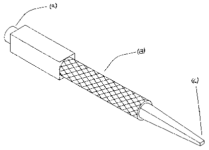
Fig.l is a orthographic view of a typical brad set.
Fig.? is a front view of a typical Bradset sized and shaped for a T-head brad
nail, where
(I) is the tip of the Bradset and (2) is the T-head brad nail.
Fig.3 is a side view of a typical Bradset sized and shaped for a T-head brad
nail, where
(1) is the tip of the Bradset and (2) is the T-head brad nail.
Fig.4 is a front view of a typical Bradset sized and shaped for a medium crown
staple,
where (3) is the tip of the Bradset and (4) is the medium crown staple.
Fig.S is a side view of a typical Bradset sized and shaped for a large crown
staple,where
(3) is the tip of the Bradset and (4) is the medium crown staple.
Detailed Description of the Preferred Embodiment
Referring to the drawings for the purpose of illustrating a preferred
embodiment of the
presented invention and not for limiting same, FIG. 2 and FiG. 3 show a
bradset for use in
recessing mechanically driven fasteners of various sizes beneath the surface
of the work piece.
The typical bradset consists of a striking face (a) to be impacted with a
suitable tool such as a
hammer, an elongated main body (b) and a specifically shaped tip (c) to fully
engage the head of
the fastener.
The exact shape and dimensions of the tip correspond to the head of the
fastener for
which it is designed.
While the above features and advantages of this invention have been described
with
reference to a preferred embodiment of the bradset. other renditions will
become apparent to
those skilled in the art. Accordingly, the presented invention embraces all
subsequent renditions
and are to be solely defined by the appended claims.

Representative Drawing
A single figure which represents the drawing illustrating the invention.
Administrative Status

2024-08-01:As part of the Next Generation Patents (NGP) transition, the Canadian Patents Database (CPD) now contains a more detailed Event History, which replicates the Event Log of our new back-office solution.

Please note that "Inactive:" events refers to events no longer in use in our new back-office solution.

For a clearer understanding of the status of the application/patent presented on this page, the site Disclaimer , as well as the definitions for Patent , Event History , Maintenance Fee  and Payment History  should be consulted.

Event History

Description Date
Application Not Reinstated by Deadline 2008-09-08
Time Limit for Reversal Expired 2008-09-08
Inactive: Adhoc Request Documented 2008-06-10
Deemed Abandoned - Failure to Respond to Maintenance Fee Notice 2007-09-06
Application Published (Open to Public Inspection) 2007-03-06
Inactive: Cover page published 2007-03-05
Inactive: IPC assigned 2005-10-31
Inactive: First IPC assigned 2005-10-31
Inactive: Office letter 2005-10-18
Application Received - Regular National 2005-10-13
Filing Requirements Determined Compliant 2005-10-13
Inactive: Filing certificate - No RFE (English) 2005-10-13

Abandonment History

Abandonment Date Reason Reinstatement Date
2007-09-06

Fee History

Fee Type Anniversary Year Due Date Paid Date
Application fee - small 2005-09-06
Owners on Record

Note: Records showing the ownership history in alphabetical order.

Current Owners on Record
GARY DOUGLAS CLINKER
Past Owners on Record
None
Past Owners that do not appear in the "Owners on Record" listing will appear in other documentation within the application.
Documents

To view selected files, please enter reCAPTCHA code :


To view images, click a link in the Document Description column. To download the documents, select one or more checkboxes in the first column and then click the "Download Selected in PDF format (Zip Archive)" or the "Download Selected as Single PDF" button.

List of published and non-published patent-specific documents on the CPD .

If you have any difficulty accessing content, you can call the Client Service Centre at 1-866-997-1936 or send them an e-mail at CIPO Client Service Centre.


Document
Description 
Date
(yyyy-mm-dd) 
Number of pages   Size of Image (KB) 
Drawings 2005-09-06 2 18
Description 2005-09-06 2 88
Abstract 2005-09-06 1 10
Claims 2005-09-06 1 16
Representative drawing 2006-01-26 1 8
Cover Page 2007-02-23 1 29
Filing Certificate (English) 2005-10-13 1 158
Notice: Maintenance Fee Reminder 2007-06-07 1 121
Courtesy - Abandonment Letter (Maintenance Fee) 2007-11-01 1 173
Second Notice: Maintenance Fee Reminder 2008-03-10 1 120
Notice: Maintenance Fee Reminder 2008-06-09 1 122
Correspondence 2005-10-13 1 9