Note: Descriptions are shown in the official language in which they were submitted.
CA 02518433 2005-09-07
WO 2004/084782 PCT/US2004/006917
THERMAL THERAPY SLEEVE
SAC~~CGROIJN~ OF THE INVENTION
The use of cold or heat therapy has long been known in the medical field.
Cold therapy may be used to treat certain limb injuries, such as sprained or
strained arm or leg muscles, or injuries to joints. Generally, cold may be
applied to
these types of injuries to slow blood flow, which reduces swelling, pain, and
further
damage. Heat therapy may be used to warm or limber muscles by increasing
blood flow. For example, athletes may apply heat to thighs or calf muscles
prior to
an athletic evenfi. In another application, a' small chemical heat pack
commonly
referred to as a "heel warmer" is activated and placed against the foot of a
newborn infant to increase the infant's blood flow prior to drawing a blood
sample.
A number of products may be used to provide heat or cold therapy. For
example, chemical heat or cold products involve a bag or pack containing two
or
more reagents separated by a membrane. When the user ruptures the membrane,
the reagents mix and undergo either an exothermic or endothermic reaction.
This
type of product provides the user instant heat or cold. When the heating or
cooling
effect subsides, the product is disposed of. Other thermal therapy products,
for
example, gel-based hot or cold packs, are reusable but require the user to
supply
external energy before use, e.g., heat from a microwave oven or cold from a
freezer. These products are often less effective than instant chemical hot or
cold
packs because they are unable to maintain the desired minimum or maximum
temperature.
The thermal therapy techniques of the prior art present two challenges.
First, many disposable thermal therapy products, while convenient, are unable
to
deliver or absorb heat for an extended duration. Second, many existing thermal
therapy products cause temperature spikes that may result in discomfort to the
user, while others are unable to attain the desired therapeutic temperature.
Thus,
there is a need for a device that provides an extended therapeutic benefit at
the
desired temperature while eliminating undesirable temperature peaks.
CA 02518433 2005-09-07
WO 2004/084782 PCT/US2004/006917
SUMMARY OF THE INVENTION
The present invention relates to a thermal therapy sleeve that extends the
therapeutic duration of a thermoactive material. The sleeve may generally
include
a first layer including an array of non-communicating chambers containing a
first
phase change material. It may further include a second layer. TIIe first layer
may
be joined to the second layer to form at least a partial enclosure having an
opening
through which a thermoactive material may be inserted and removed. In some
embodiments, fibs second layer may include an array of non-communicating
chambers containing a second phase change material. In some instances, the
first
to phase change material may be chemically identical to the second phase
change
material.
The present invention further relates to a thermal therapy sleeve that may
include a first layer formed from a matrix of fibers, where the fibers may
rmed
include a polymer and a first phase change material. The sleeve may further
15 include a second layer joined to the first layer to form at least a partial
enclosure
having an opening through which a thermoactive material may be inserted and
removed. In some embodiments, the second layer may be formed from a matrix of
fibers, where the fibers may include a polymer and a second phase change
material. In some instances, the first phase change material and the second
2o phase change material may be chemically identical. The fibers that form the
first
layer and /or the second layer may each include from about 1 mass % to about
50
mass % of the first phase change material.
The present invention also relates to a thermal therapy sleeve including a
first layer formed from a matrix of polymeric fibers and a first encapsulated
phase
2s change material, and a second layer joined to the first layer to form at
least a
partial enclosure having an opening through which a thermoactive material may
be
inserted and removed. The second layer may include a matrix of polymeric
fibers
and a second phase change material. In some embodiments, the first phase
change material and the second phase change material may be chemically
3o identical. The mafirix may include from about 1 mass °/~ to about 70
mass °/~ of the
first encapsulated phase change material.
The present invention finally relates to a thermal therapy system having an
extended therapeutic duration including a thermoactive material and a flexible
sleeve into which the thermoactive material is inserted. The thermoactive
material
2
CA 02518433 2005-09-07
WO 2004/084782 PCT/US2004/006917
may include a chemical pack having at least a first compartment and a second
compartment separated by a membrane, where the first compartment contains a
solute and the second compartment contains a solvent, and where the rupturing
of
the membrane causes the mia~ing of the solute and solvent and produces an
~ endothermic reach~n of an e~zothermic reaction. The sleeve may include a
first
layer including a first phase change material, and a second layer joined to
the first
layer to form at least a partial enclosure having an opening through which the
thermoactive material may be inserted and removed. In some embodiments, the
second layer may include a second phase change material that may, if desired,
be
to chemically identical to the first phase change material.
BRIEF DESCRIPTION OF THE DRAWINGS
FIG. 1. depicts an exemplary thermal therapy sleeve for use with the present
invention, where a layer of the sleeve includes hollow chambers containing a
15 phase change material.
FIG. 2 depicts an exemplary thermal therapy sleeve for use with the present
invention, where a layer of the sleeve is formed from a coextruded polymer and
phase change material.
FIG. 3 depicts an exemplary thermal therapy sleeve for use with the present
2o invention, where a layer of the sleeve is formed from a matrix of fibers
and an
encapsulated phase change material.
FIG. 4 depicts the experimental setup used to measure time-temperature
data for various thermal therapy systems evaluated in Examples 1 and 2.
FIG. 5 depicts a comparison of time-temperature profiles for three
25 exemplary calcium chloride chemical pack systems evaluated.
FIG. 6 depicts the temperature between the bottom surface of the sample
and the metal plate as' a function of time for three exemplary calcium
chloride
chemical pack systems.
FIG. 7 depicts the temperature between the top surface of the sample and
3o the insulation as a function of fiime for three exemplary calcium chloride
chemical
pack systems.
FIG. ~ depicts the difference between the temperature between the bottom
surface of the sample and the metal plate and the temperature between the top
3
CA 02518433 2005-09-07
WO 2004/084782 PCT/US2004/006917
surface of the sample and the insulation as a function of time for three
exemplary
calcium chloride chemical pack systems.
FIG. 9 depicts the experimental setup used to measure time-temperature
data for various thermal therapy systems evaluated in Examples ~, 4, and 5.
FIG. 10 depicts the temperature as a function ~f time for an eacemplary
system including octacosane.
FIG. 11 depicts the temperature as a function of time for an exemplary
system including eicosane.
FIG. 1 ~ depicts the temperature as a function of time for an e3zemplary
to system including 50/50 mixture of octacosane and eicosane.
FIG. 13 depicts a comparison of fihe data of FIG.'S 10-12.
FIG. 14 depicts a comparison of the time-temperature data for various
exemplary systems including no phase change material, tetradecane, hexadecane,
and a 50/50 mixture of pentadecane and tetradecane.
15 FIG. 15 depicts the temperature as a function of time for various exemplary
hot and cold pack systems including no phase change material and a 50/50
mixture of eicosane and pentadecane.
DESCRIPTION OF THE INVENTION
20 The present invention relates to a thermal therapy system that features an
extended therapeutic life. The extended life is attributed to use of at least
one
phase change material (PCM) in cooperation with traditional thermal therapy
techniques. In particular, the PCM is incorporated into a thermal therapy
sleeve
into which a thermoactive material is inserted. A "thermoactive material" is
any
2s substance that is able to provide or absorb heat at room temperature, or
multiple
substances that generate or absorb heat when combined by, for example, an '
exothermic reaction or endothermic reaction, respectively. Thermoactive
materials
include, for example, ice, gels, chemical reagents such as salts and water,
and the
like. Thermoactive materials may be provided in a package or may otherwise be
3o contained for user convenience. For instance, many thermoactive materials
are
incorporated into instant chemical hot or cold packs, commercially available
gel
packs, metal oxidation products, and the like, also referred to as "thermal
therapy
products" herein. More particularly, a "cold therapy product" refers to a
product
4
CA 02518433 2005-09-07
WO 2004/084782 PCT/US2004/006917
that consumes heat and provides a cooling effect, and a "heat therapy product"
refers to a product that generates or emits heat and provides a warming
effect.
The thermal therapy system of the present invention overcomes the
deficiencies of the prior art by providing a flexible, reusable thermal
therapy sleeve
sued to accomm~date a thermoactive material. The sleeve confains a PCli~i that
may be regenerated Pay simply replacing the spent thermoactive material, for
example, a thermal therapy product such as a chemical or gel-based hot or cold
pacl~. ~y doing so, the duration of the thermal therapy is extended. This
presents
a significant advantage over current products that require inconvenient and
time-
Zo consuming external regeneration using an independent energy source, such as
placement in a cool ,(e.g. freezer) or warm (e.g. microwave) environment for a
lengthy period of time prior to reuse.
The PCM may be incorporated into the sleeve in a variety of manners, such
as, for example, by including it in hollow chambers within a layer of the
sleeve, by
15 co-extruding it with fibers that form a layer of the sleeve, or by
integrating an
encapsulated form of the PCM into the fibrous matrix of a layer of the sleeve.
The present invention also relates to a method of extending the therapeutic
life of a thermal therapy product. In general, a traditional thermal therapy
product
may be used with the thermal therapy sleeve of the present invention to both
2o modulate the temperature of the traditional product and extend the
therapeutic
duration of the product.
To better understand what is contemplated by the present invention, a more
detailed description is provided below.
A material typically consumes or releases thermal energy in proportion to its
25 heat capacity, which varies as a function of temperature. The variation in
heat
capacity is small if the material does not undergo a phase transition within
the
temperature range of interest. There is, however, a nonlinear change in heat
capacity at or around the temperature of phase change, i.e., the transition
temperature, that typically allows a much larger amount of thermal energy to
be
~o either consumed by or released from the material as the material melts or
freezes,
respectively.
Phase change materials (PCM's) are materials that are able to undergo a
reversible phase firansition at a precise temperature. Common PCM's include,
for
example, low molecular weight aliphatic hydrocarbons, paraffin waxes, and
acids
CA 02518433 2005-09-07
WO 2004/084782 PCT/US2004/006917
of natural oils and waxes. , Paraffinic hydrocarbons are well-suited for
attaining the
desired temperature for a given thermal therapy application because there is a
fairly strong correlation between the number of carbon atoms in the
hydrocarbon
and its melting point. Thus, for a given application, the desired therapeutic
temperature may readily be attaine~9 by selection of the appropriate PCii/I or
combination of PCf~i's. Various exemplary parafFinic hydrocarbons are listed
below.
Compound Carbon atoms Transition tem erature
C
n-Octacosane 28 61.4
n-Heptacosane 27 59.0
n-Hexacosane 26 56.4
n-Pentacosane 25 53.7
n-Tetracosane 24 50.9
n-Tricosane 23 47.6
n-Docosane 22 44.4
n-Hemeicosane 21 40.5
n-Eicosane 20 36.8
n-Nonadecane 19 32.1
n-Octadecane 18 28.2
n-He tadecane 17 22.0
n-Hexadecane 16 18.2
n-Pentadecane 15 10.0
n-Tetradecane 14 5.9
n-Tridecane 13 ~ -5.5
so Fatty acids of natural oils, alcohols, and waxes may be . alternatively be
used. Though not intended to be exhaustive, various non-paraffinic PCM's that
may be used with the present invention are set forth below.
Compound ~~ _ Transition temperature
(C
Cet I alcohol 45-50
Ste I alcohol 54-57
Lanette wax 50
Stearic acid commercial reds 52-56
Stearic acid natural 64
Palmitic acid commercial reds 58
Palmitic acid natural 63
fill ristic acid 54
Coconufi oil partially hydro 44.5
enated
Sesame oil artiall h dro enated62.1
Whale oil artiall h dro enated 45.1
Arachis oil artiall h dro enated51.2
6
CA 02518433 2005-09-07
WO 2004/084782 PCT/US2004/006917
Cottonseed oil artiall hydro 38.5
enated
Tallow (full h dro enated 62
Lard fully h dro enated 64
Cocoa butter (fully hydrogenated)64
Arachis fully h dro enated 65
Cod liver fully h dro enated 55
Linseed full hydro enated 58
Sesame fully h dro enated 68.5
~live fully h dro enated 70
Poppy (fully hydrogenated) 70.5
Almond full hydro enated 72
Castor wax ~ 85
Phase change materials (PCM's) may be used to enhance thermal therapy by
extending the therapeutic life of any thermoactive material. Specifically, a
PCM
may be used to control the heat generated, emitted, or consumed by a thermal
therapy product.
° In an instant chemical thermal therapy pack, a salt is separated from
water
by a membrane. The user is instructed to break the membrane separating the two
reagents by twisting, squeezing, or stretching the pack. Usually there is an
instant
chemical reaction upon mixing of the salt and water that results in a sharp
increase
or decrease of the local temperature. For instance, in an instant hot pack,
heat
can be generated by dissolving a salt such as calcium chloride in water. This
' reaction has an exothermic heat of reaction of 215 cal/g. Similarly, in an
instant
cold pack, heat can be consumed by dissolving a salt such as ammonium nitrate
in
water. This reaction has an endothermic heat of reaction of 77 cal/g. The heat
released or consumed in typical chemical thermal therapy product is rapidly
dissipated through the minimal insulation provided by the material from which
it is
formed.
The advantages of using a PCM in conjunction with an instant hot or cold
pack may be seen by examining a typical commercially available chemical cold
pack. As described above, a chemical cold pack consumes heat from its
surroundings when activated, usually by rupturing a membrane separating two or
more reagents. An appropriate PCM positioned inside the thermal therapy
product
or within the surrounding area modulates the increase or decrease in
temperature.
As the pack cools, heat is removed from the liquid PCM, causing it to undergo
a
phase change, i.e., to solidify or freeze. The solidified PCM maintains the
7
CA 02518433 2005-09-07
WO 2004/084782 PCT/US2004/006917
decreased temperature for an extended period of time, as it will require heat
to
cause the PCM to undergo a phase change back to the liquid state. The heat
required to melt the PCM does not contribute to a rise in the temperature
until all of
the solidified PCM has melted. Thus, the temperature experienced by the user
does not increase as rapidly. In this manner it is possible to manage the heat
flow
t~ provide a comfortable therapeutic temperature and extend the duration of
the
therapeutic benefit.
There are other advantages of using a PCM in conjunction with traditional
thermal therapy products. First, a greater selection of chemical reagents may
be
used in a chemical pack without concern for undesirable temperature peaks. As
heat is rapidly absorbed or released, the PCM modulates fihe temperature
actually
experienced by the user. This provides a significant advantage over
traditional
thermal therapy products that are limited to certain reaction chemistries that
generate or consume a certain amount of heat for some duration at a given
solute
concentration. Furthermore, for the same quantity of reagents, a longer
duration of
therapy may be provided, and in some instances, the quantity of reagents may
be
decreased so a less bulky product may be made.
There are various considerations in selecting an appropriate PCM and the
mass of phase change material to be used for a given application. First, the
minimum or maximum temperature to be experienced by the user must be
determined. For example, for an infant heel warmer application, the maximum
permissible temperature may be about 104°F (40°C).
For some adult warming applications, such as short-term spot treatment,
the maximum experienced temperature may be about 130°F (54°C).
For some
adult applications, such as tong-term patient warming, the maximum experienced
temperature may be about 108°F (42°C). For other adult warming
applications,
the minimum experienced temperature may be about 99°F (37°C).
For some adult cooling applications, such as short-term spot treatment, the
minimum. experienced temperature may be about 33°F (0°C). For
other adult
cooling applications, the minimum experienced temperature may be about
39°F
(4°C). For some adult cooling applications, the maximum experienced
temperature may be abut 99°F (37°C).
Once the desired temperature for a given application is established, at least
one PCM having a transition temperature near that temperature is selected so
the
8
CA 02518433 2005-09-07
WO 2004/084782 PCT/US2004/006917
PCM will undergo a phase transition at or near the desired therapeutic
temperature. The amount of PCM used for a given application depends on the
amount and type of the thermoactive material used. In general, enough PCM
should be used so that all of the heat released or absorbed by the
thermoactive
material is fully utilised in effecting a phase change of fihe PCi~.
In some embodiments, the present invention may be used to extend the
therapeutic benefit of a cold therapy product. In such instances, the PCM may
have a transition temperature of from about -~0°C to about 40°C.
More
particularly, in some embodiments, the PCM may have a transition temperature
of
from about 0°C to about 37°C. Examples of PCM's that may be used
include, for
example, n-tridecane, n-tetradecane,n-pentadecane, n-hexadecane, n-
heptadecane, n-octadecane, n-nonadecane, n-eicosane, and combinations
thereof. However, it should be understood that other suitable PCM's may be
used.
Alternatively, the present invention may be used to extend the therapeutic
duration of a heat therapy product. In such instances, the PCM may have a
transition temperature of from about 35°C to about 65°C. More
particularly, in
some embodiments, the PCM may have a transition temperature of from about
37°C to about 54°C. Examples of PCM's that may be used include,
for example,
n-eicosane, n-hemeicosane, n-docosane, n-tricosane, n-tetracosane, n
pentacosane, n-hexacosane, n-heptacosane, n-octacosane, and combinations
thereof. However, it should be understood that other suitable PCM's may be
used.
For some applications, it may be desirable to use multiple PCM's to further
extend the therapeutic duration of the thermoactive material. In some
embodiments, the combination of PCM's may be chosen so that all of the PCM
present undergoes a phase transition at or near the desired therapeutic
temperature. In other embodiments, the PCM's may be chosen to provide therapy
at two or more temperature levels. Any of the above PCM's may be used as
additional PCM's. It should be understood, however, that other PCM's are
available and any suitable PCM may be used.
Incorporation of the PCM into the thermal therapy sleeve presents unique
challenges. Many PCM's are liquids or become liquids at the transition
temperature, and therefore need to be contained in some manner to prevent
leakage from the product into which the PCM is incorporated. One means of
9
CA 02518433 2005-09-07
WO 2004/084782 PCT/US2004/006917
containing a liquid PCM is to enclose a quantity of the PCM in a discrete
pocketed
region or hollow chamber within the product. When the PCM becomes a liquid, it
is then contained within the space provided and is not able to migrate to
other
regions or outside of the product.
Alternatively, PCIV~'s that become a liquid at the transition temperature may
be encapsulated in the form of microparticles using a temperature-stable
material,
for example, silica, as the outer shell. The encapsulated PCM is then able to
consume or release heat in a reversible manner when exposed to temperatures
higher or lower than its melting point. When a PCfVI is adsorbed onto silica
particles, such as those obtained from Phase Change Laboratories, Inc. (10109
Carroll Canyon Road, San Diego, CA 92131 ), the silica particles maintain
their dry
powder-like properties even at temperatures above the transition temperature.
Encapsulated PCM's may be incorporated into various substrates using a
multitude of techniques. Examples of such techniques include applying a
coating
of an encapsulated PCM on the surface of fibers or films such that the
particles
adhere to the fiber or film surface, integrating the encapsulated PCM into
polymeric fibers, co-extruding fibers from aqueous solutions of polymers mixed
with a slurry of an encapsulated PCM, confining the encapsulated PCM in the
blister of a blister-pack type laminate, impregnating the encapsulated PCM
into a
polymeric foam, dispersing the encapsulated PCM in a polymeric resin and
subsequently crosslinking the resin to entrap the particles in the polymer
matrix,
entangling the encapsulated PCM within a fine fiber nonwoven material
structure
during the manufacturing process, and printing the encapsulated materials onto
the substrate.
Any suitable technique or plurality of techniques may be used to incorporate
the PCM into the thermal therapy sleeve of the present invention, and the
technique selected may depend on the design of the product into which the PCM
is
incorporated.
The design of the sleeve may vary for a given application. It may be sized
or shaped so that a particular part of the body may be exposed or covered
entirely.
It may include adhesive, ties, or other means to fasten the product to the
body or
clothing of the user. It may include aesthetic features, such as a cotton or
nonwoven outer cover to improve comfort for the user. Ifi may be sealable or
may
be open on one or more edges for easy insertion and removal of the
thermoactive
CA 02518433 2005-09-07
WO 2004/084782 PCT/US2004/006917
material. It may include one or more insulating materials to improve
performance
and comfort.
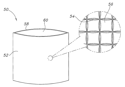
In one embodiment depicted in FIG. 1, the thermal therapy sleeve 50 may
include a first layer 52 including an array of non-communicating chambers 54
or
pockets containing a first PCM 56. It may further include a second layer 58
joined
to the second layer to form at least a partial enclosure having an opening 60
through which a thermoactive material (not shown) may be inserted and removed.
In some embodiments, the second layer may include an array of non
communicating chambers containing a second PCM. The first PCM may, in some
instances, be chemically identical to the second PCM.
In another embodiment depicted in FIG. 2, the PCM may be incorporated
directly into fibers that form a layer 52 of the sleeve 50 by coextruding the
PCM
with a polymeric material. This process~'may result in a polymeric fiber
sheath 62
having a PCM core 64. It may alternately result in a fiber having a side-by-
side
configuration in which there is a polymer portion and a PCM portion. Other
possible configurations will be known to those of skill in the art. Any
polymer may
be used, and in some embodiments, the polymeric fiber is formed from a
polyolefin, such as polypropylene or polyethylene. In some embodiments, the
resulting fiber may include from about 1 mass % to about 50 mass % PCM. In
other embodiments, the fiber may include from about 5 mass % to about 30 mass
PCM. In yet other embodiments, the fiber may include from about 10 mass % to
about 20 mass % PCM.
In such an embodiment, the thermal therapy sleeve 50 may include a first
layer 52 formed from a matrix of fibers, where the fibers may include a
polymer 62
and at least one PCM 64. The sleeve may include second layer 58 joined to the
first layer to form at least a partial enclosure having an opening 60 through
which a
thermoactive material (not shown) may be inserted and removed. In some
embodiments, the second layer may also include a matrix of fibers, where the
fibers may be formed from a polymer and at least one PCM. A benefit of using
such a composite fiber in a thermal therapy sleeve is that a higher mass of
PCM
by percent may be obtained. Additionally, the PCM is integral to the
structure, so
there is little risk that the PCM will mobilize and leak out of the sleeve.
In yet another embodiment depicted in FIG. 3, the PCM may be incorporated
into the sleeve by physically entangling an encapsulated PCM within the
polymeric
. 11
CA 02518433 2005-09-07
WO 2004/084782 PCT/US2004/006917
fiber matrix during or after formation of the fibers. The low mass of the
particles
enables them to adhere to the fibers by electrostatic forces. Addition of
particles to
various substrates, particularly nonwoven or airlaid materials is well-known
in the art.
In some embodiments, the resulting matrix may include from about 1 mass ~/~ to
about ~0 mass ~/~ encapsulated PCi~i. In other embodiments, the matrix: may
include from about 25 mass ~/~ to about 50 mass ~/~ encapsulated PCM. In yet
other embodiments, the matrix may include from about 30 mass ~/~ to about 40
mass ~/~ encapsulated PCM.
/here this approach is used, fibs thermal therapy sleeve 50 may include a
to first layer 52 formed from a matrix of polymeric fibers 66 and an
encapsulated
PCM 63, and a second layer 53 joined to the first layer to form at least a
partial
enclosure having an opening 60 through which a thermoactive material (not
shown) may be inserted and removed. In some embodiments, the second layer
may also include a matrix of polymeric fibers and a second encapsulated PCM.
The second .encapsulated PCM may, if desired, be chemically identical to the
first
encapsulated PCM.
Any suitable method of incorporating a PCM into the present invention may
similarly be used to form a sleeve having multiple PCM's, and the PCM's may be
incorporated into the same layer or separate layers. Such a sleeve may be used
2o where two therapeutic temperatures are desired. A sleeve that ofFers such
dual
functionality may provide a benefit to the user, such as product versatility
and user
convenience. For instance, the present invention contemplates a sleeve that
may
be used with both heat and cold therapy. ~ne such sleeve may include a first
side
or layer that may be placed in contact with the user when a cold therapy
product is
used as the thermoactive material, and a second side or layer that may be
placed
in contact with the user when a heat therapy product is used as the
thermoactive
material. Alternatively, the sleeve may include the PCM's needed to extend
both a
cold benefit and a heat benefit within the same layer or on the same side of a
sleeve so that a user may receive the extended therapeutic benefit of heat or
cold
3o therapy on one side of the sleeve, or on bofih sides of the sleeve
simultaneously.
For instance, in one embodiment, the thermal therapy sleeve may include a
first layer into which a first PCM has been incorporated, and a second layer
into
which a second PCfifi has been incorporafied. As stated previously, the
PCI~I's
may be chemically identical, similar, or distinct, depending on the
application and
12
CA 02518433 2005-09-07
WO 2004/084782 PCT/US2004/006917
the desired therapeutic temperature and duration. In one embodiment, the first
PCM may have a transition temperature of from about -10°C to about
40°C, and
the second PCM may have a transition temperature of from about 35°C to
about
65°C. In another embodiment, the first PCM may have a transition
temperature of
from about 0°C to about 37°C, and the second PCM may have a
transition
temperature of from about 37°C to about 54°C.
In another embodiment, the sleeve may include a first layer into which a first
PCM and a second PCM are incorporated. In one such embodiment, the first PCM
may have a transition temperature of from about -10°C to about
40°C and fibs
second PCM may have a transition temperature of from about 35°C to
about 65°C.
In another such embodiment, the first PCM may have a transition temperature of
from about 0°C to about 37°C and the second PCM may have a
transition
temperature of from about 37°C to about 54°C. In some
embodiments, such a
sleeve may include a second layer into which a third PCM is incorporated. The
third PCM may be chemically identical, similar, or distinct from the first and
second
PCM's. While a sleeve with three PCM's is described herein, it should be
understood that additional PCM's may be used depending on the application and
the desired therapeutic temperature and duration.
The layers of the sleeve may be made from a wide variety of materials,
including, for example, woven reusable fabrics and nonwoven disposable fabrics
or webs. Nonwoven materials suitable for use with the present invention
include,
for example, a multilayer laminate such as a spunbond/meltblown/spunbond
("SMS") material. An example of such a fabric is disclosed in U.S. Patent No.
4,041,203 and is hereby incorporated by reference.
As used herein the term "nonwoven fabric or web" means a web having a
structure of individual fibers or threads that are interlaid, but not in an
identifiable
manner as in a knitted fabric. Nonwoven fabrics or webs have been formed from
many processes such as for example, meltblowing processes, spunbonding
processes, and bonded carded web processes.
As used herein the term "spunbond fibers" or "spunbonded fibers" refers to
small diameter fibers which are formed by extruding molten thermoplastic
material
as filaments from a plurality of fine, usually circular capillaries of a
spinneret with the
diameter of the extruded filaments then being rapidly reduced, for example, as
in
U.S. Patent 4,340,563 to Appel et al., and U.S. Patent 3,692,618 to Dorschner
et al.,
13
CA 02518433 2005-09-07
WO 2004/084782 PCT/US2004/006917
U.S. Patent 3,802,817 to Matsuki et al., U.S. Patents 3,338,992 and 3,341,394
to
Kinney, U.S. Patent 3,502,763 to Hartman, and U.S. Patent 3,542,615 to Dobo et
al.
Spunbond fibers are generally not tacky when they are deposited onto a
collecting
surface. Spunbond fibers are generally continuous and have average diameters
~ (from a sample of at least 10) larder than 7 microns, more particularly,
between
about 10 and 20 microns.
As used herein the term "meltblown fibers" means fibers formed by
extruding a molten thermoplastic material through a plurality of fine, usually
circular, die capillaries as molten threads or filaments into converging high
velocity,
to usually hot, gas (e.g. air) streams that attenuate the filaments of molten
thermoplastic material to reduce their diameter, which may be to microfiber
diameter. Thereafter, the meltblown fibers are carried by the high velocity
gas
stream and are deposited on a collecting surface to form a web of randomly
dispersed meltblown fibers. Such a process is disclosed, for example, in U.S.
m Patent 3,849,241 to Butin et al. Meltblown fibers are microfibers that may
be
continuous or discontinuous, are generally smaller than 10 microns in average
diameter, and are generally tacky when deposited onto a collecting surface.
p As used herein the term "multilayer laminate" means a laminafie in which
some of the layers are spunbond or some meltblown such as a
2o spunbond/meltblown/spunbond (SMS) laminate and others as disclosed in U.S.
Patent 4,04.1,203 to Brock et al., U.S. Patent 5,169,706 to Collier, et al.,
U.S. Patent
5,145,727 to Potts et al., U.S. Patent 5,178,931 to Perkins et al. and U.S.
Patent
5,188,885 to Timmons et al. Such a laminate may be made by sequentially
depositing onto a moving forming belt first a spunbond fabric layer, then a
meltblown
a5 fabric layer and last another spunbond layer and then bonding the laminate
in a
manner described below. Alternatively, the fabric layers may be made
individually,
collected in rolls, and combined in a separate bonding step. Such fabrics
usually
have a basis weight of from about 0.1 to 12 osy (6 to 400 gsm), or more
particularly
from about 0.75 to about 3 osy. Multilayer laminates may also have various
3o numbers of meltblown layers or multiple spunbond layers in many different
configurations and may include other materials like fiilms or coform
materials, e.g.
SMMS, SM, SFS, etc.
As used herein the term "coform" means a process in which at least one
meltblown diehead is arranged near a chute through which other materials are
14
CA 02518433 2005-09-07
WO 2004/084782 PCT/US2004/006917
added to the web while it is forming. Such other materials may be pulp,
superabsorbent particles, cellulose or staple fibers, for example. Coform
processes
are shown in commonly assigned U.S. Patents 4,51 x,464 to Lau and 4,100,324 to
Anderson et al. webs produced by the coform process are generally referred to
as
"cofiorm materials".
The sleeve may also include a metallized film, foil, or the like. One material
that may be suitable for use with the present invention is a metallized
plastic film,
for example, SiIverPAl~" polyester barrier, available from t~apak Corporation
of
Minneapolis, iUlf~.
The components of the sleeve may be produced separately and assembled
by for example, thermal bonding, adhesive bonding, ultrasonic bonding, or
stitching. Other means of assembly will be readily known by those of skill in
the
art. Alternatively, each layer of the sleeve may be constructed as a single
multilayer unit followed by die cutting and some means to join the layers. The
layers of the sleeve may be joined at any suitable location as desired. Thus,
the
layers may be joined at or near a single edge, or at or near a plurality of
edges, as
desired or needed to accomplish the purpose of the present invention.
The components of the sleeve may be chemically, mechanically,
electrostatically, or otherwise treated to provide additional functional or
aesthetic
2o attributes, such as softness, stretch, absorbency, repellency, odor
reduction, skin
care, or the like.
The present invention further contemplates a thermal therapy system
having an extended therapeutic duration. The system includes a thermoactive
material that may include a chemical pack sized to fit within a thermal
therapy
sleeve. The pack may be divided into at least a first compartment and a second
compartment by a membrane, where the first compartment contains a solute and
the second compartment contains a solvent, and where the rupturing of the
membrane causes the combination of the solute and solvent and produces an
endothermic reaction or an exothermic reaction. The system may further include
a
flexible sleeve including a first layer into which a first PCM is
incorporated, and a
second layer joined to the first layer to form at least a partial enclosure
having an
opening through which the thermoactive material may be inserted and removed.
In some embodiments, fihe second layer may include a second PCM, that may, if
desired, be chemically identical to the first PCM.
CA 02518433 2005-09-07
WO 2004/084782 PCT/US2004/006917
The PCM may be incorporated into the sleeve using any suitable technique.
In some embodiments, the first layer may include an array of non-communicating
chambers containing the first PCM. In other embodiments, the first layer may
include a matrix of fibers, where the fibers are formed from a polymer and the
first
PCM. In yet other embodiments, the first layer may include a matri~z of
polymeric
fibers and the first PCM. In such embodiments, the PCM may be encapsulated. In
all such embodiments described above, addifiional layers having additional
PCM's
may be incorporated, and any suitable technique may be used to incorporate the
second PCM into the second layer.
In yet other embodiments, a PCM may be included within the thermal
therapy product in addition to including the same or another PCM within the
sleeve. In one embodiment, the thermal therapy product may be a chemical pack
including one or more PCM's. The PCM may be incorporated into the pack as a
separate component separated by a membrane or may be mixed with the solute or
solvent, or both, as desired. In another embodiment, the thermal therapy
product
may be a gel-based product that includes one or more PCM's. In yet another
embodiment, the thermal therapy product may be a metal oxidation product that
includes one or more PCM's.
The present invention further contemplates a method of extending the
therapeutic life of a thermal therapy product. The method generally includes
selecting a thermal therapy product to provide a benefit to a user, selecting
a PCM,
incorporating the PCM into a thermal therapy sleeve and placing the thermal
therapy product inside the thermal therapy sleeve. The sleeve may be any
sleeve
contemplated by the present invention and may include first layer and a second
layer, where the first layer is joined to the second layer to form at least a
partial
enclosure having an opening through which the thermal therapy product may be
inserted and removed. The thermal therapy product may be selected to provide a
heat benefit to the user. Alternatively, the thermal therapy product may be
selected to provide a cold benefit to the user. Any suitable PCM or
combination of
PCM's may be used as described herein.
The method may also include activating the thermal therapy product. The
technique by which the product is activated depends on the type of product
selected by the user. In one embodiment, fihe fihermal therapy product may
include a chemical pack that is activated by breaking a membrane that
separates
16
CA 02518433 2005-09-07
WO 2004/084782 PCT/US2004/006917
two reagents. For example, a chemical heat pack may include a first
compartment
and a second compartment separated by a membrane, where the first
compartment contains a solute and the second compartment contains a solvent.
The rupturing of the membrane in a heat pack causes the combination of the
solute and solvent and produces an eazothermic reaction. Likewise, a chemical
cold pack may include a first compartment and a second compartment separated
by a membrane, where the first compartmenfi contains a solute and the second
compartment contains a solvent. The rupturing of the membrane in a cold pack
causes the combination of the solute and solvent and produces an endothermic
to reaction. Such chemical packs are generally disposable. For some warming
applications, the exothermic reacfiion of calcium chloride and water may be
used.
For some cooling applications, the endothermic reaction of ammonium nitrate
and
water may be used. However, it should be understood that other exothermic and
endothermic reaction chemistries are contemplated by the present invention.
Such
15 products may be activated before insertion into the sleeve, or after
insertion, as
desired.
In another embodiment, the product is a gel-based product that is activated
by exposing it to an energy source. One such product may be activated by
placing
it in a cool environment, such as a refrigerator, to provide cold therapy. In
yet
2o another embodiment, the product is a gel-based product that is activated by
placing it in a warm environment, such as a microwave oven, to provide heat
therapy. Such gel-based products may be reusable upon regeneration, i.e.,
repeated exposure to the appropriate energy source or temperature environment.
In still another embodiment, the thermal therapy product is a metal oxidation
25 product, for example, an iron oxidation product, that is activated by
exposing the
product to air. Such products are often disposable.
The method of the present invention further includes removing the thermal
therapy product from the sleeve for disposal, regeneration, or replacement of
the
product. In this manner, the sleeve may be used multiple times for heat or
cold
o therapy or may be regenerated to continue the therapeutic benefit of a
particular
heat or cold therapy session.
The present invention further contemplates a mefihod of making a thermal
therapy system having an extended therapeutic life. The method includes
selecting a solute and a solvent such that the mixing of the solute and the
solvent
17
CA 02518433 2005-09-07
WO 2004/084782 PCT/US2004/006917
results in an endothermic or exothermic reaction, and depositing the solute
and the
solvent in a pack. The pack may be divided into at least a first compartment
and a
second compartment by a membrane, where the first compartment contains the
solute and the second compartment contains the solvent. The rupturing of the
membrane causes tile mi~;ing of the solute and solvent. Any suitable chemical
reagents may be used as described above.
The method further includes selecting a PCM and incorporating fibs PCM
into a thermal therapy sleeve. The sleeve may be any sleeve contemplated by
the
present invention, and may include a first layer and a second layer, where the
first
Zo layer is joined to the second layer to form at least a parfiial enclosure
having an
opening through which the pack may be inserted and removed. The method
further includes placing the pack into the thermal therapy sleeve, and
activating the
pack.
The present invention also contemplates a method of making a thermal
therapy system having an extended therapeutic life. The method includes
providing a reusable heat or cold thermal therapy product, selecting a PCM,
incorporating the PCM into a thermal therapy sleeve, and providing an energy
source to activate the product prior to placing the product into a thermal
therapy
sleeve. The sleeve may be any thermal therapy sleeve contemplated by the
2o present invention, and may include a first layer and a second layer, where
the first
layer is joined to the second layer to form at least a partial enclosure
having an
opening through which the product may be inserted and removed.
So that the invention may be more readily understood, reference is made to
the following examples. The examples are intended to be illustrative of the
invention
but are not intended to be limiting in scope.
EXAMPLE 1
The ability to modulate the temperature of a chemical heat product using a
PCM was demonstrated. In this example, the sleeve was constructed from a
3o nonwoven material, as described below.
Preparation of Control Sleeve
Two pieces of a 2.0 ounces per square yard (osy) fine fiber polypropylene
meltblown nonwoven material were laminated together to prepare the first layer
of
the control sleeve. A 12 in. (304 mm) by 12 in. (304 mm) Carver hot press
(Carver
18
CA 02518433 2005-09-07
WO 2004/084782 PCT/US2004/006917
model 1523) was used to laminate the materials together at a temperature of
145°C and a pressure of 12,000 psi for 2 minutes. Another two pieces of
the same
material were laminated together in the same manner to prepare the second
layer
of the control sleeve. An ultrasonic bonder was then used to bond the two
laminates on three sides to form the control sleeve. The resulting sleeve had
a
mass of about 7.0 c~.
Preparation of Experimental Sleeve
Two pieces of a 2.0 ounces per square yard (osy) fine fiber polypropylene
meltblown nonwoven material were laminated together to prepare the first layer
of
to the experimenfial sleeve. A 12 in. (304 mm) by 12 in. (304 mm) Carver hot
press
(Carver m~del 1523) was used to laminate the materials together at a
fiemperature
of 145°C and a pressure of 10,000 psi for 2 minutes. Prior to
lamination, about 7.2
g of 127°F (53°C) transition temperature PCM (available from
Phase Change
Laboratories, Inc. of San Diego, CA) was placed between the layers. The
resulting
s5 mass of the first layer was about 10.7 g.
Another two pieces of the same material were laminated together in the
same manner to prepare the second layer of the experimental sleeve. Prior to
lamination, about 6.9 g of 127°F (53°C) transition temperature
PCM (available from
Phase Change Laboratories, Inc, of San Diego, CA) was placed between the
ao layers. The resulting mass of the second layer was about 10.1 g.
An ultrasonic bonder was then used to bond the two laminates on three
sides to form the experimental sleeve. The resulting sleeve contained about
67.8
mass % of PCM.
Preparation of Chemical Pack
25 A metallized plastic film laminate (SiIverPAK° 2.5 mils (0.025 in.)
thick
polyester barrier from Kapak Corporation of Minneapolis, MN) was used to make
a
pouch to hold approximately 10 g of calcium chloride (CaCl2) powder (VWR
Catalog number EM-CX0156-1 ). A 4.5 in. (114 mm) by 4.5 in. (114 mm) pouch
was made by bonding the laminates on three sides using an ultrasonic bonder.
3o After filling the pouch with the CaCh powder, the fourth side of fihe pouch
was
sealed using a pressure sensitive adhesive tape.
Experimental Design
The experimental setup depicted in FIG. 4 was used to measure the
temperature profile of fihe CaCl2 hot pack upon introduction of 10 ml of
deionized
19
CA 02518433 2005-09-07
WO 2004/084782 PCT/US2004/006917
water. Polystyrene foam insulation 20 was used to cover the sample 22. The
control and test sleeves were enclosed in another SiIverPAK° layer to
obtain a
uniform surface temperature. The sample 22 was placed on an aluminum plate 24
in contact with the surface of a circulating water bath 26 to provide a
consfiant
s temperature. Two temperature measurements were taken: T~, the temperature
between the bottom surface of the sample and the metal plate, and T2, the
temperature between the top surface of the sample and the insulation.
Results
FIG. 5 depicts the temperature profile for T2 as a function of time for the
to three cases evaluated: the foil pouch containing calcium chloride (depicted
as
curve ,A); the foil pouch with calcium chloride inserted into the control
sleeve
(depicted as curve B); and T2 for the foil pouch with calcium chloride
inserted infio
the test sleeve (depicted as curve C). . Curve C shows a reduced peak
temperature
and an extended duration. Thus, the results indicate that the presence of PCM
in
15 the test sleeve modulates both the peak temperature and the duration of
heat
release from the calcium chloride pack.
2o EXAMPLE 2
The ability to modulate the temperate of a chemical pack using a PCM was
demonstrated. In this example, the sleeve was constructed from a metallized
film
as described below.
Preparation of Control Sleeve D
25 Two pieces of a metallized plastic film laminate bag (SiIverPAK° 2.5
mils
(0.025 in. thickness) polyester barrier from Kapak Corporation of Minneapolis,
MN)
were sealed together using epoxy adhesive. Note that this sleeve did not have
a
pocketed laminate structure of control sleeve E and experimental sleeve F.
Preparation of Control Sleeve E
3o Two pieces of the same metallized plastic film laminate bag were laminated
together to prepare the first layer of the control sleeve. The pieces were
laminated
using a 12 in. (304 mm) by 12 in. (304 mm) Carver hot press (Carver model
1523)
at a temperature of aboufi X35°C and a pressure of about X0,000 psi for
a duration
of about 1 minute. Another two pieces of the same material were laminated
CA 02518433 2005-09-07
WO 2004/084782 PCT/US2004/006917
together in the same manner to prepare the second layer of the control sleeve.
A
high strength epoxy adhesive was then used to bond two layers on three sides
to
make the control sleeve. The resulting mass of the sleeve was about 9.0 g.
Preparation of E~zperimental Sleeve F
Two pieces of a metalli~.ed plastie film laminate bag (SiIverPAl~~ 2.5 mils
(0.025 in. thickness) polyester barrier from l~apal< Corporation of
Minneapolis, iVii~)
were laminated together to prepare the first layer of the experimental sleeve.
Prior
to lamination, about 10.7 g of 127°F (53°C) transition
temperature PCM (available
from Phase Change Laboratories, Inc. of San Diego, CA) was placed between the
so two pieces. The pieces were laminated using a 12 in. (304 mm) by 12 in.
(304
mm) Carver hot press (Carver model 1523) at a temperature of about
135°C and a
pressure of about 10,000 psi for a duration of about 1 minute. The resulting
mass
of the first layer was about 15.3 g.
Another two pieces of the same material were laminated together in the
15 same manner to prepare the second layer of the experimental sleeve. Prior
to
lamination, about 9.8 g of 127°F (53°C) transition temperature
PCM .(available from
Phase Change Laboratories, Inc. of San Diego, CA) was placed between the
layers. The resulting mass of the second layer was about 14.5 g.
A high strength epoxy adhesive was then used to bond two layers on three
2o sides to make the experimental sleeve.
Preparation of Samples D, E, and F
Sample D was then formed by placing 10 g of CaCl2 into control sleeve D
and closing the sleeve using an adhesive tape at the open end. Sample E was
formed by placing 10 g of CaCl2 into control sleeve E and closing the sleeve
using
25 an adhesive tape at the open end. Sample F was formed by placing 10 g of
CaCl2
into experimental sleeve F and closing the sleeve using an adhesive tape at
the
open end. Sample F contained about 68.8 mass % of PCM.
Experimental Design
The samples were then evaluafied using the experimental setup used in
3o Example 1. Polystyrene foam insulation was placed on top of each sample to
insulate it from the air. A syringe was used to inject 10 ml of deioni~ed
water infix
each sample. The resulting temperature profiles for T~ and T2 were measured as
a
function of time.
21
CA 02518433 2005-09-07
WO 2004/084782 PCT/US2004/006917
Results
FIG.'s 6, 7, and 8 show the profiles of T~, T2, and (T~ - T2), respectively,
as
a function of time. As seen in FIG. 6, the peak temperature decreased for the
experimental sample F containing the PCM as compared with control samples D
s and E. The ea~perimental sample F ea~hibited a slightly delayed decay of the
temperature with time; however, most of the heat generated was quickly removed
through the lower side of the pack to the circulating water bath.
FIG. ~ shows a large plateau in T~ for the experimental sample F compared
with the two control samples D and E. Since the heat transfer on the upper
side of
2o the sleeve was limited due to the polystyrene foam insulation, there was
significant
accumulation of heafi over time on this surface. In the case of control
samples D
and E, the decay of accumulated heat was much more rapid than that for the
experimental sample F, which contained the PCM.
A much more pronounced difference between the three temperature profiles
s5 is seen in FIG. 8. The difference between T~ and T~ was initially positive
(T~ is
greater than T2), followed by a sharp transition to a negative value (T~ is
lower than
T2). This indicates that there was a significant heat accumulation on the T2
side
once the chemical reaction was initiated. This accumulation of heat was
gradually
dissipated by heat transfer through the thickness of the sample to the
circulating
2o water bath. This decay was much slower for the experimental sample F than
for
the control samples D and E. The additional heat storage capacity~of the PCM
in
the experimental sample F caused a much slower dissipation of heat.
EXAMPLE 3
25 The ability to extend the therapeutic duration of a thermal therapy heat
pack
and modulate the experienced temperature using multiple PCM's was
demonstrated.
To understand the effect of combining multiple PCM's within the thermal
therapy sleeve, the PCM's were evaluated individually and in combination. The
3o first PCM selected was octacosane (transition temperature of about 61
°C,
available from Aldrich Chemical under the catalog number ~-50-4.). The second
PCM selected was eicosane (transition temperature of about 37°C,
available from
Aldrich Chemical under the catalog number 2~,92~-4.).
22
CA 02518433 2005-09-07
WO 2004/084782 PCT/US2004/006917
Small pouches (about 4 in. (102 mm) by about 2 in. (51 mm) were made
using two pieces of a metallized plastic film laminate bag (SiIverPAK~ 2.5
mils
(0.025 in. thickness) polyester barrier from Kapak Corporation of Minneapolis,
MIlI). Each was filled with about 10 g of PGM in the liquid state. The first
pouch
contained octacosane (pouch H), and the second pouch contained eicosane
(pouch I). The pouches were sealed using a thermal impulse sealer and allowed
to cool to solidify the PCM. A third pouch was made with a 50/50 mixture of
octacosane and eicosane (pouch J).
Four chemical heat packs were formed as in Example 2 using the Kapak
to material. Each pack was filled with about 75 g deionized water. Immediately
before taking measurements, about 50 g of CaCl2 was added to fihe pack. ~ne
pack was formed as a control (sample G).
The experimental setup used in FIG. 9 was used to collect time-temperature
data for each of the samples. The sample pouch 28 was placed on the test
surface 30. The chemical heat pack 32 was placed on top of the sample pouch
28. Polystyrene foam insulation 20 was used to cover the system. Two
temperature measurements were taken: T~, the temperature between the bottom
surface of .the sample pouch and the test surface, and T2, the temperature
between the top surface of the sample pouch and the bottom surface of the
2o chemical pack. The data was collected using a DT9805 A/D board (Data
Translation) and LabTech Data Acquisition software. The results of the
analyses
are depicted in FIG.'s 10, 11, 12, and 13.
FIG. 10 depicts the results for sample H containing the octacosane. The
presence of octacosane lowered the peak temperature that would be felt on the
therapeutic side (the side with the PCM that would contact the skin). However,
the
quantity of heat generated by activation of the hot pack was not enough to
melt the
entire mass of the phase change material. Therefore, there the heat
modulafiion
was not optimized.
FIG. 11 depicts the results for sample I containing the eicosane. The
3o presence of eicosane lowered the peak temperature and modulated the heat
flow
since the quantity of heat generated was enough to melfi the entire mass of
the
PCM.
FIG. 12 depicfis the results for sample J containing the 50/50 mixture of
octacosane and eicosane. When mixed in this manner, both octacosane and
23
CA 02518433 2005-09-07
WO 2004/084782 PCT/US2004/006917
eicosane influenced the time-temperature profile of the chemical pack. A
higher
peak temperature was observed due to the presence of the higher melting
octacosane. However, only the eicosane melted completely to modulate the heat
flow at its transition temperature of 35°C. A summary of the results is
presented
below.
PCiitl Peak t3~ (fiime to
Temperature reach
Test surface 30C during the
coolin base
Control fro PCM 30 - 35C 55 minutes
~ctacosane 35C 50 - 60 minutes
Eicosane 33C 30 miriutes
50/50 Eicosaneloctacosane45C 70 minutes
As can be seen in FIG. 13, using eicosane in combination with octacosane
(curve J), the temperature was modulated at 35°C and the duration of
thermal
Zo delivery was increased by approximately 45%, when compared with the control
sample (curve G), the octacosane sample (curve H), and the eicosane sample
(curve I). Curve K represents an ambient temperature baseline for reference
purposes. The results indicate that the peak temperature experienced by the
test
surface may be raised by using a combination of PCM's. Although there was a
slight reduction in total duration of heat delivery, two levels of
temperatures may be
useful in certain therapies.
EXAMPLE 4
The ability to extend the therapeutic duration of a thermal therapy cold pack
2o and modulate the experienced temperature using multiple PCM's was
demonstrated.
The same procedure was carried out as in Example 3, except that a cold
pack was used. The following PCM's were used: pentadecane (transition
temperature of about 10°C, Aldrich Catalog number P-340-6), tetradecane
(sample
M, transition temperature of about 6°C, Aldrich Catalog number 17,245-
6), and
hexadecane (sample l~, transition temperature of about 13°C, Aldrich
Catalog
number 29,631-7). Sample ~ contained a 50/50 mixture of pentadecane and
tetradecane. The chemical pack contained 35 g deioni~ed water, to which 100 g
24
CA 02518433 2005-09-07
WO 2004/084782 PCT/US2004/006917
ammonium nitrate (NH4N03) was added immediately prior to taking
measurements.
FIG. 14 depicts a summary of the results. The ambient temperature
baseline is presented as curve S. Using the combination of PCM's (curve O),
there was a considerable r-nodulation of the peak temperature compared to the
control (curve P). The increase in the therapeutic duration was not as readily
apparent, since the temperature profile during the re-warming phase was quite
shallow. This effect was most likely obserrved due to the slow, continuous
dissolution of the salt in water. Since salt solubility decreases at low
temperatures,
Zo not all of the salt dissolved in the water immediately. Once the chemical
pack
began to re-warm, more of the salt dissolved, causing a delay in re-warming.
Consequently, the phase change effect was not as prominent as in the case of
the
instant hot pack. However, there may be applications in which such effects can
be
minimized.
EXAMPLE 5
The ability to extend the therapeutic duration of both a hot chemical pack
and a cold chemical pack using a thermal therapy sleeve with multiple PCM's
was
2o demonstrated.
Four small pouches (about 4 in. (102 mm) by about 2 in. (51 mm) were
made using two pieces of a metallized plastic film laminate bag
(SiIverPAK° 2.5
mils (0.025 in. thickness) polyester barrier from Kapak Corporation of
Minneapolis,
MN). Two of the pouches (pouch U and pouch Y) were filled with about 10 g of a
50/50 mixture of eicosane and pentadecane.
Four chemical packs were formed as in Example 2 using the Kapak
material. Each pack was filled with about 75 g deionized water. Immediately
before taking measurements, about 50 g of chemical reagent was added to the
pack. Pack T was designafied as a control pack to which CaCh was added. Pack
3o U was designated as an experimental pack to which CaCl2 was added. Pack X
was designated as a control pack to which NH,~N03 was added. Pack Y was an
experimental pack to which NH~N03 was added.
The experimental setup used in FIG. 9 was used to collect time-temperature
data for each of the samples. The sample pouch 2~ was placed on a the test
CA 02518433 2005-09-07
WO 2004/084782 PCT/US2004/006917
surface 30. The chemical.heat pack 32 was placed on top of the sample pouch
28. Polystyrene foam insulation 20 was used to cover the system. Two
temperature measurements were taken: T~, the temperature between the bottom
surface of the sample pouch and the test surface, and T2, the temperature
~ between the top surFace of the sample pouch and the bottom surface of the
chemical pack. The data was collected using a ~T9305 ~/~ board (~ata
Translation) and LabTech ~ata Acquisition software. The results of the
analyses
are depicted in FIG. 15. The room temperature over time is depicted as curve
~.
As shown in FIG. ~5, the PCM mixture was able to modulate the
Zo temperature of both a hot chemical pack (curve U) and a cold chemical pack
(curve Y), as compared with the control systems (curve T and curve X,
respectively), resulting in a more moderate and longer-lasting temperature
profile.
The amount and types of PCM's may be modified to optimize the modulation
within
different temperature ranges.
15 In summary, the present invention addresses the need for a thermal therapy
system that reaches the desired therapeutic temperature, eliminates
undesirable
temperature spikes, and provides an extended therapeutic duration. By
incorporating one or more PCM's into a thermal therapy sleeve, the benefits
traditional form of thermal therapy may be enhanced and extended: Further, the
2o thermal therapy system of the present invention may be used to provide a
beneficial product combination to the user by providing a thermoactive
material,
such a chemical pack, a gel-based pack, or a metal oxidation product, and the
sleeve into which the material is inserted. This combination is both
efficacious and
convenient and ofFers significant benefits over products currently available.
2s Furthermore, the methods contemplated by the present invention offer an
array of
thermal therapy possibilities for various applications.
The invention may be embodied in other specific forms without departing
from the scope and spirit of the inventive characteristics thereof. The
present
embodiments therefore are fio be considered in all respects as illustrative
and not
~o restrictive, the scope of the invention being indicated by the appended
claims
rather than by fibs foregoing description, and all changes which come within
the
meaning and range of equivalency of the claims are therefore intended to be
embraced fiherein.
26