Note: Descriptions are shown in the official language in which they were submitted.
CA 02518477 2005-09-07
60.1555/1570-CIP
MICROFLUIDIC SEPARATOR
FIELD OF THE INVENTION
The present invention relates to chemical analysis and, more particularly, to
the
separation of fluids in microfluidic systems.
BACKGROUND
The ability to reliably separate a fluid of interest can be very beneficial
for oilfield,
medical, biological, and analytical chemistry applications. Fluids of interest
may include
water, oil, gas, or other fluids. Separating fluids of interest enables
specific measurements to
be performed on the particular fluid. For example, pH and various ion
concentrations may be
measured if the fluid of interest is water. For oil, near-infrared absorption
spectroscopy may
be performed to detect various light-weight hydrocarbons, and other types of
chromatography
may be used to detect detailed chemical composition.
However, in order to perform accurate measurements on the fluid of interest,
the fluid
of interest must be separated from other components prior to taking the
measurements. The
separation methods conventionally used in the oilfield include gravity
separation,
centrifugation, and hydrocyclone separation. Conventional methods are used to
separate
large quantities (i.e. for production purposes) and have several drawbacks.
One drawback of
conventional separation techniques is the time it takes to perform them.
Conventional
separation techniques often take a long time, depending on the particular
composition of the
fluid. For example, a fine emulsion may take months to separate by gravity,
although a
simple mixture may take only a few minutes. Another drawback of conventional
separation
techniques is poor separation performance. Conventional separation techniques
usually do
not perform a complete separation. There are almost always traces of
contaminants in the
sample fluid of interest.
In addition, in most oilfield applications, analyses of formation fluids of
interest are
typically performed at the surface adjacent to the well or in a remote
laboratory environment.
However, bringing sample fluids to the surface, transporting them to a
laboratory, and
separating the phase mixtures is time consuming, cost inefficient and provides
only post-
factum information. Moreover, fluid samples collected downhole can undergo
various
CA 02518477 2005-09-07
60.1555/1570-CIP
reversible and irreversible phase transitions between the point of collection
and the point of
laboratory analysis as pressure and temperature conditions change.
Recently, biologists and analytical chemists have started to perform analysis
of
various fluids in laboratories on a micro-scale. The analysis of minute fluid
amounts is
accomplished with various microfluidic and/or MEM (Micro Electro-Mechanical)
systems.
Microfluidic systems or devices are typically comprised of fluidic channels
with lateral
dimensions ranging from tens to hundreds of micrometers and are designed to
operate with
extremely small volumetric flow rates. However, similar to analysis on a macro-
scale, at the
micro-scale it is equally necessary to separate the fluid of interest from
other fluids in order to
perform an effective analysis. Prior to a co-pending patent application number
10/885,471
filed July 6, 2004 as attorney docket number 60.1555 and entitled
"Microfluidic System for
Chemical Analysis," which is hereby incorporated in its entirety by this
reference,
microfluidic devices for oilfield applications have only been suitable for use
in laboratory
environments.
Accordingly, there is a need for a microfluidic separator capable of
separating
emulsions, liquid-liquid and liquid-gas mixtures in any environment, including
uphole and
downhole oilfield environments. There is also a need for a microfluidic
separator which is
addressable remotely from surface in oilfield environments.
SUMMARY OF THE INVENTION
The present invention addresses the above-described deficiencies and others.
Specifically, the present invention provides methods and apparatus for
separating and/or
analyzing fluids of interest. According to principles of the present
invention, fluid analysis is
accomplished with microfluidic devices and methods and may be reported in real-
time or
near real-time from a subterranean environment.
One aspect of the present invention provides a fluid separation method. The
method
comprises separating a multiphase mixture with a membrane in a microfluidic
device. The
method may also include maintaining a pressure difference across the membrane
below a
capillary break-through pressure of a nonwetting component of the multiphase
mixture. The
method may include inserting the membrane and the microfluidic device into a
subterranean
oilfield environment. Thus, the separation may comprise separating the
multiphase mixture
in a wellbore, while drilling (MWD), during wireline operations, or during
permanent
2
CA 02518477 2005-09-07
60.1555/1570-CIP
production logging. The separation may also be done at a surface location.
According to
some aspects, the separation further comprises flowing the multiphase mixture
across the
membrane in a direction substantially parallel to the membrane. The separation
method may
include flowing one phase of the multiphase mixture through pores of the
membrane. The
separation may comprise separating one liquid of the multiphase mixture from
another liquid
or gas, or separating a gas from a liquid of the multiphase mixture. A
pressure differential
may be created across the membrane in the microfluidic device to facilitate
separation.
According to some aspects, the membrane may be a water-repellant, oil-
permeable
membrane; an oil-repellent, water-permeable membrane; an oil-and-water-
repellent gas
permeable membrane, or other membrane. A liquid of interest from the
multiphase mixture
may flow through the membrane at a flow rate at least one-to-two orders of
magnitude lower
than a flow rate of the multiphase mixture passing by the membrane. The
separation may
comprise passing a liquid of interest from the multiphase mixture through the
membrane and
preventing the membrane from fouling without back-flushing. After separation,
the fluid of
interest may pass into an H-fractal fluid channel configuration.
According to another aspect of the invention, a fluid separation method
comprises
separating a first liquid in a multiphase mixture from a second liquid in the
multiphase
mixture with one of a membrane or a plurality of microfabricated pores in a
microfluidic
device. The membrane and the microfluidic device may be inserted into a
subterranean
oilfield environment. Thus, the separating may comprise separating the first
liquid in a
wellbore. The separating may also comprise part of: a measurement while
drilling operation,
a wireline operation, or a permanent production logging operation.
Another aspect of the invention provides a method of testing a subterranean
fluid in
situ. The method includes separating a liquid of interest from another liquid
downhole in a
microfluidic device, passing the separated liquid of interest into a
microfluidic analyzer,
analyzing the liquid of interest, and reporting the analysis uphole in near
real-time. The
analysis may comprise continuously passing a new supply of the separated
liquid of interest
into the microfluidic analyzer. The analyzing may comprise passing a new
supply of the
separated liquid of interest at different depths in a wellbore during a
drilling or wireline
logging operation, or during permanent monitoring.
The present invention also provides an apparatus, including a microfluidic
device
comprising a porous membrane for separating a multiphase mixture. The
microfluidic device
may be surrounded by a submersible housing. The membrane may be a hydrophobic
3
CA 02518477 2005-09-07
60.1555/1570-CIP
membrane, an oleophobic membrane, a hydrophobic/oleophobic gas permeable
membrane, or
some other separation membrane. The membrane may comprise PTFE, polyethylene,
polypropylene, nylon, or other materials. The apparatus may include a
microsieve adjacent to
and downstream of the membrane. The porous membrane may be mechanically
connected or
adhesively connected to the microsieve. Various chemical modifications may be
performed
on the porous membrane in order to increase its adhesive properties. The
apparatus may
include a downhole oilfield tool having a fluid flow stream, such that the
microfluidic device
is disposed in the fluid flow stream and the porous membrane is arranged
substantially
tangent to a flow direction of the fluid flow stream. The microfluidic device
may have a
sample manipulation/analysis module or chip. The microfluidic device may also
include a
capillary gas separator downstream of the porous membrane. The capillary gas
separator
may comprise microfabricated channels arranged substantially tangent to a
fluid stream
downstream of the porous membrane. The microfabricated channels may comprise
pores of
approximately 10 microns or less. The microfluidic device may include a
secondary fluid
outlet channel tangentially downstream of the capillary gas separator, and an
oil outlet
downstream of the capillary gas separator.
Another embodiment of the present invention comprises a microfluidic system
for
performing fluid analysis comprising a submersible housing having a fluid
analyzer and a
power supply to provide power to said system, a substrata for receiving a
multiphase mixture
through a fluid sample inlet, wherein the substrate interconnects with the
housing, and a
membrane disposed across the fluid sample inlet for separating a fluid of
interest from the
multiphase mixture.
Another aspect of the invention provides a method of separating a multi-phase
mixture,
comprising: sending the multi-phase mixture containing a fluid of interest
through a
microfluidic channel in contact with a membrane wet by one or more non-fluids
of interest
contained in the mixture, permeating the one or more non-fluids of interest
through the
membrane, and leaving a stream of the fluid of interest to flow to an outlet
of the channel.
Another aspect of the invention provides a method of separating a multi-phase
mixture of two or more immiscible fluids, comprising: sending the multi-phase
mixture
through a first microfluidic channel in contact with a membrane wet by a first
of the two or
more immiscible fluids, passing the first fluid through the membrane,
collecting the first fluid
in a second microfluidic channel, directing the first fluid to an outlet of
the second
microfluidic channel, and leaving a second of the two or more immiscible
fluids to flow to an
4
CA 02518477 2013-07-08
69897-78
outlet of the first microfluidic channel. The method may further include
analyzing the first and
second fluids.
Another aspect of the present invention provides an apparatus, comprising: a
microfluidic device comprising a porous membrane for separating a multiphase
mixture in a
fluid flow stream within a structure wherein a pressure difference across the
porous membrane
is maintained below a capillary break-through pressure of a nonwetting fluid
phase present in
the multiphase mixture; wherein the porous membrane is arranged substantially
tangent to an
intended fluid flow direction of the multiphase mixture present in the fluid
flow stream and
disposed across a fluid sample inlet to the microfluidic device; and a
microsieve structured
and arranged adjacent to and downstream of the membrane and includes a
capillary fluid
separator having microfabricated channels arranged substantially tangent to
the fluid stream
downstream of the porous membrane.
Another aspect of the present invention provides a microfluidic system for
performing fluid analysis, comprising: a submersible housing having a fluid
analyzer and a
power supply to provide power to said system; a substrate for receiving a
multiphase mixture
through a fluid sample inlet, wherein said substrate interconnects with said
submersible
housing; and a membrane disposed across the fluid sample inlet for separating
a fluid of
interest from the multiphase mixture; and wherein the substrate includes
fabricated channels,
such that the fabricated channels are arranged substantially tangent to the
fluid stream
downstream of the porous membrane.
Another aspect of the present invention provides an apparatus, comprising: a
housing having a fluid flow stream, such that the housing is positioned in a
downhole oilfield
tool; a microfluidic device positioned in the housing comprising a porous
membrane for
separating a multiphase mixture in the fluid flow stream wherein a pressure
difference across
the porous membrane is maintained below a capillary break-through pressure of
a nonwetting
fluid phase present in the multiphase mixture; wherein the porous membrane is
arranged
substantially tangent to an intended fluid flow direction of the multiphase
mixture present in
the fluid flow stream; and a microsieve structured and arranged adjacent to
and downstream
of the porous membrane and includes a capillary fluid separator having
microfabricated
5
CA 02518477 2013-07-08
69897-78
channels arranged substantially tangent to the fluid stream downstream of the
porous
membrane.
Another aspect of the present invention provides a fluid separation method,
comprising: a substrate for receiving a multiphase mixture through an inlet of
a microfluidic
device, wherein said substrate interconnects with a housing of the
microfluidic device; a
porous membrane disposed across the inlet for separating a fluid of interest
from the
multiphase mixture wherein the substrate includes microfabricated channels,
such that the
microfabricated channels are structured and arranged between the porous
membrane and the
substrate; and separating the multiphase mixture with the porous membrane in
the
microfluidic device.
Another aspect of the present invention provides a fluid separation method,
comprising: a substrate for receiving a multiphase mixture through an inlet of
a microfluidic
device, wherein said substrate interconnects with a housing of the
microfluidic device; a
membrane disposed across the inlet for separating a first liquid of interest
from the multiphase
mixture wherein the substrate includes microfabricated channels, such that the
microfabricated channels are structured and arranged between the membrane and
the
substrate; and separating the first liquid of interest in the multiphase
mixture from a second
liquid of interest in the multiphase mixture with one of the membrane or a
plurality of
microfabricated pores in the microfluidic device.
Another aspect of the present invention provides a method of testing a
subterranean fluid in situ, comprising: a substrate for receiving a multiphase
mixture through
an inlet of a microfluidic device, wherein said substrate interconnects with a
housing of the
microfluidic device; a membrane disposed across the inlet for separating a
fluid of interest
from the multiphase mixture wherein the substrate includes microfabricated
channels, such
that the microfabricated channels are structured and arranged between the
membrane and the
substrate; and separating the fluid of interest from another fluid downhole in
the microfluidic
device; passing the separated fluid of interest into a microfluidic analyzer;
analyzing the fluid
of interest and reporting the analysis uphole in near real-time.
5a
CA 02518477 2013-07-08
69897-78
Another aspect of the present invention provides a method of separating a
multiphase mixture having at least one fluid of interest and at least one
fluid not of interest,
comprising: a substrate for receiving the multiphase mixture through an inlet
of a microfluidic
device, wherein said substrate interconnects with a housing of the
microfluidic device; a
membrane disposed across the inlet for separating a fluid of interest from the
multiphase
mixture wherein the substrate includes microfabricated channels, such that the
microfabricated channels are structured and arranged between the membrane and
the
substrate; and sending the multi-phase mixture through a microfluidic channel
in contact with
the membrane wet by the at least one fluid not of interest; permeating the one
or more fluids
not of interest through the membrane; and leaving a stream of the at least one
fluid of interest
to flow to an outlet of the microfluidic channel.
Another aspect of the present invention provides a method of separating a
multiphase mixture of two or more immiscible fluids, comprising: a substrate
for receiving the
multiphase mixture through an inlet of a microfluidic device, wherein said
substrate
interconnects with a housing of the microfluidic device; a membrane disposed
across the inlet
for separating a fluid of interest from the multiphase mixture wherein the
substrate includes
microfabricated channels, such that the microfabricated channels are
structured and arranged
between the membrane and the substrate; and sending the multi-phase mixture
through a first
microfluidic channel in contact with the membrane wet by a first of the two or
more
immiscible fluids; passing the first fluid through the membrane; collecting
the first fluid in a
second microfluidic channel; directing the first fluid to an outlet of the
second microfluidic
channel; leaving a second of the two or more immiscible fluids to flow to an
outlet of the first
microtluidic channel.
Additional advantages and novel features of the invention are set forth in the
description which follows or may be learned by those skilled in the art
through reading these
materials or practicing the invention. The advantages of the invention may be
achieved
through the means recited in the attached claims.
5b
CA 02518477 2013-07-08
69897-78
BRIEF DESCRIPTION OF THE DRAWINGS
The accompanying drawings illustrate preferred embodiments of the present
invention and are a part of the specification. Together with the following
description, the
drawings demonstrate and explain the principles of the present invention.
Fig. 1 is a schematic diagram of a sample tool with a microfluidic device and
a
separator according to one embodiment of the present invention.
Fig. 2 is a representative diagram illustrating wetting properties of two
different fluids with respect to a pore.
Fig. 3 is a block diagram illustrating details of the microfluidic device and
1 0 separator of Fig. 1 according to one embodiment of the present
invention.
Fig. 4 is an illustration of an H-fractional microfluidic channel arrangement
according to one embodiment of the present invention.
Fig. 5 is a schematic diagram illustrating a second separator that may be
combined with the separator shown in Figs. 1-2 according to one embodiment of
the present
invention.
Fig. 6 is an illustration of one application of the present invention, useful
for
oilfield fluid monitoring and water management.
Fig. 7 is a representation of a microfluidic separator and method of
separating
according to another aspect of the present invention.
Fig. 8 is a representation of another microfluidic separator and method of
separating that may enable analysis of multiple fluids of interest according
to another aspect
of the present invention.
Sc
CA 02518477 2005-09-07
60.1555/1570-CIP
DETAILED DESCRIPTION
Illustrative embodiments and aspects of the invention are described below. It
will of
course be appreciated that in the development of any such actual embodiment,
numerous
implementation-specific decisions must be made to achieve the developers'
specific goals,
such as compliance with system-related and business-related constraints that
will vary from
one implementation to another. Moreover, it will be appreciated that such a
development
effort might be complex and time-consuming but would nevertheless be a routine
undertaking
for those of ordinary skill in the art having the benefit of this disclosure.
The present invention contemplates methods and apparatus for separating
multiphase
mixtures including liquid-gas mixtures, liquid-liquid mixtures, and emulsions,
especially in
microfluidic devices. As mentioned in the background, in many applications,
including oil
well evaluation and aquifer management, fluid samples must be separated and
analyzed. The
principles described herein facilitate separation of liquid-liquid mixtures
and liquid-gas
mixtures. The separation according to the present invention may take place in
a downhole
environment during wireline operations, while drilling (Logging While Drilling
(LWD)/Measurements While Drilling (MWD)), during permanent production logging,
and is
not limited to laboratory conditions. However, the principles described herein
may be used at
a surface or laboratory location as well. Application of the principles of the
present invention
may be used, for example, to provide continuous real-time or near real-time
data concerning
formation fluid in a subterranean formation.
As used throughout the specification and claims, the terms "microfluidic
system" or
"microfluidic device" mean a network of one or more channels with dimensions
of tens to
hundreds of micrometers that may have one or more components including, but
not limited
to: pumps, valves, mixers, integrated optical fibers, and other components
integrated on a
chip for the purpose of manipulating and/or analyzing minute amounts of fluid.
The term
"tangentially downstream" refers to a fluid stream, a portion of which is
flowing by, rather
than through, a stated component. "To foul" means to become clogged,
obstructed, or
blocked. "Fluid" means a continuous, amorphous substance whose molecules move
freely
past one another and that has the tendency to assume the shape of its
container, including
both liquids and gases. In the context of membranes, "hydrophobic" is the
property of a
material of not being wet by water (water impermeable). "Hydrophilic" is the
property of
being wet by water (water permeable). "Oleophobic" means not wet by oil (oil
impermeable)
6
CA 02518477 2005-09-07
60.1555/1570-CIP
and "oleophilic" means wet by oil (oil permeable). "Microsieve" refers to a
network of
microchannels in contact with a membrane used for collecting a fluid of
interest permeating
through a membrane. The words "including" and "having," as used in the
specification,
including the claims, have the same meaning as the word "comprising."
While the present invention is described herein according to certain
particular
embodiments and may be well suited to oilfield applications, the present
invention is not so
limited. The principles of the present invention may be extended to any
application wherein
multi-phase separation may be useful. For example, the principles of the
present invention
may be applied to biological samples, chemical samples, or any other
microfluidic samples
and are not limited to oilfield applications.
Many types of small-scale sensors are currently being considered in the oil
industry,
in particular for performing measurements in downhole environments.
Miniaturized sensors
capable of monitoring pressure, density, viscosity, and temperature are
currently being
developed and used. There are several reasons behind this trend toward
miniaturization,
including reduced fabrication costs (such sensors can be batch-produced),
smaller size (a
sensitive parameter given the limited space available in the downhole
environment), and
lower power consumption. In addition, using miniaturized sensors such as a
fluid analyzer in
accordance with principles of the present invention, measurements typically
involving large
lab equipment may instead be performed downhole in the natural environment.
Among the properties that could not be fully characterized downhole prior to
the
present invention is the chemical composition of the various fluids extracted
from the
formation. As mentioned in the background, one obstacle to downhole chemical
analysis is
efficiently separating phases (e.g. oil, water, gas, particulates,
contamination from drilling
muds, etc.). Filtering usually fails due to filter fouling, and gravitational
separation based on
density mismatch is extremely slow. Accelerated separation methods such as
centrifugation
and hydrocyclone separation are difficult to implement and impractical in a
downhole
environment.
Therefore, according to the present invention, a microfluidic device or system
100
shown in Fig. 1 includes a multi-phase separator that may be used in downhole
environments
without the tendency to foul. The description that follows includes a
discussion of apparatus
according to principles of the present invention, followed by a description of
microfluidic and
microanalysis systems in general, and an explanation of methods of practicing
the invention.
7
CA 02518477 2005-09-07
60.1555/1570-CIP
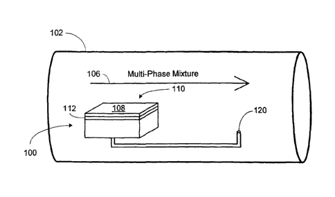
Fig. 1 illustrates a sampling tool 102 in fluid communication with formation
fluid
mixtures. An intended flow direction of fluids with respect to the sampling or
drilling tool
102 is represented by an arrow 106.
According to principles of the present invention, the multi-phase separator of
the
microfluidic device 100 shown in Fig. 1 relies on differences in wetting
behavior between
various fluids on certain materials and microstructures in order to perform
separation of the
multi-phase fluids. Certain materials and microstructures contain pores or
capillaries which
are wetted by certain fluids but not by others. For example, referring to Fig.
2, a pore 107 is
wet by Fluid A but not by Fluid B. Therefore, Fluid A flows freely through the
pore 107
whereas the nonwetting Fluid B forms a meniscus 109 which prevents Fluid B
from entering
the pore 107. If pressure applied across the pore 107 becomes larger than a
certain
breakthrough pressure, Fluid B will enter the pore 107. However, if the
pressure of Fluid B is
maintained below the breakthrough pressure, only Fluid A will flow through the
pore.
The magnitude of the breakthrough pressure of a fluid depends on the surface
properties (such as surface energy) of the material that incorporates the
pores, the dimensions
of the pore (such as diameter), and the surface tension of the two immiscible
fluids and of
their interface (e.g. Fluids A and B).
Returning to Fig. 1, the multi-phase separator comprises microfabricated
channels or
a porous membrane 108 disposed at or across a fluid sample inlet 110. The
porous
membrane 108 preferably has high porosity and submicron pore size. Therefore,
the porous
membrane 108 provides both capillary separation of a fluid of interest (such
as oil) from a
secondary fluid or liquid (such as water), and particulate filtering.
According to the
embodiment of Fig. 1, the membrane 108 may be made of hydrophobic, oleophilic
material;
hydrophilic, oleophobic material, or a material that is gas permeable and both
hydrophobic
and oleophobic. Other materials may also be used. The membrane 108 is capable
of liquid-
liquid separation and/or gas-liquid separation without fouling. The membrane
108 is
preferably made of a suitable chemically and thermally resistant material,
such as PTFE
(polytetrafluroethylene, known under the brand name of Teflon') for Goretex
or Porotex
membranes, polyethylene/polypropylene for Celgarde membranes, nylon, or other
material.
The membrane 108 is preferably placed across the inlet 110 adjacent to a
microsieve
112. Nevertheless, the membrane 108 may be located anywhere between the inlet
110 and an
outlet 120. The microsieve 112 is optional. However, the microsieve 112
provides a support
8
CA 02518477 2005-09-07
60.1555/1570-CIP
or backing to the membrane 108 and creates a uniform distribution of pressure
over the entire
area of the membrane 108. The microsieve 112 is preferably integrated with the
microfluidic
system 100 and may comprise a wire mesh or closely perforated plate. The
membrane 108
may be mechanically connected to the microsieve 112. The mechanical connection
between
the membrane 108 and the microsieve 112 may be achieved according to some
embodiments
by pressing the membrane 108 with an o-ring or other fastener, or it may be
adhesively
attached. Chemical modifications may be performed on the membrane material in
order to
improve its adhesive properties. The membrane 108 is preferably in direct
contact with the
microsieve 112, minimizing dead-volume issues which can become problematic in
low flow
rate regimes.
As shown in Fig. 1, the assembly comprising the membrane 108 and microsieve
112 is preferably arranged substantially tangent to or parallel with the
intended flow direction
106 of fluids flowing through or along the sampling tool 102. Furthermore, the
flow rate
through the membrane 108 is extremely low, on the order of several microliters
per minute,
which corresponds to a very low pressure drop across the membrane 108. The
pressure drop
across the membrane 108 is preferably maintained well below the pressure
necessary for
capillary break-through of the nonwetting fluid. The configuration of the
membrane 108
disposed substantially in a tangent or cross-flow direction with respect to
the fluid
advantageously results in self-cleaning of the membrane 108. The flow rate
across or passing
by the membrane 108 is at least one-to-two, and preferably several, orders of
magnitude
larger than the flow rate through the membrane 108. Therefore, cake build-up
and fouling
problems are prevented, eliminating the need to backflush.
The membrane 108 and microsieve 112 assembly may be connected to or integral
with the microfluidic system 100, which, according to the schematic embodiment
of Fig. 3, is
a microfluidic sample manipulation/analysis sensor chip 114. As shown in Fig.
3, the
microfluidic sensor chip 114 is configured to manipulate and analyze
microscopic (few
microliters and smaller) amounts of fluid. Suction pressure to assure flow
through the
membrane 108, microsieve 112 (Fig. 1), and the channels 116 disposed in the
chip 114 may
be generated either actively or statically. According to Fig. 3, a pressure
gauge 118 may
monitor the pressure drop across the membrane 108 of the chip 114. One or
several valves
124, possibly in conjunction with a micropump, may be used in order to
maintain the
pressure drop below the breakthrough pressure of the nonwetting phase, as part
of a flow
9
CA 02518477 2005-09-07
60.1555/1570-CIP
regulation system 122. However, according to other embodiments, an inherent
flow-
generated pressure drop inside a wellbore or oil pipe between the inlet 110
(Fig. 1) and an
outlet 120 (Fig. 1) of the microfluidic sensor chip 114 may provide the
suction pressure.
As a fluid of interest such as liquid oil passes through the membrane 108, it
enters an
interconnected arrangement of collection channels. According to the embodiment
of Fig. 3,
the collection channels comprise an H-fractal configuration 134. Fig. 4
illustrates details of
the H-fractal configuration. As shown in Fig. 4, the collection channels
comprise a plurality
of nodes 142, four nodes for each of a plurality of first H's 146. Fluid may
enter the
configuration 134 at each of the nodes 142. Each of the first H's 146 is in
fluid
communication with adjacent first H's 146 to form a second set of H's 147.
According to the
embodiment shown, a set of four adjacent first H's 146 cooperate to form a
second H 147.
Likewise, each of the plurality of second H's 147 is in fluid communication
with one another
to create a third plurality of H's 148. According to the embodiment shown,
four of the
second plurality of H's 147 cooperate to form a third H 148. Each of the third
plurality of
H's 148 is in fluid communication with one another to create a fourth H 150.
The pattern
shown in Fig. 4 may obviously be expanded or contracted as desired. The fourth
H 150 is in
fluid communication with a fluid outlet channel 152, which feeds into the
channel 116 shown
in Fig. 3. One advantage of the H-fractal configuration is an equidistant
fluid path length
between each node 142 and the fluid outlet channel 152. Therefore, regardless
of what node
142 a volume of fluid enters, all volumes of fluid entering the different
nodes 142 at the
approximate same time will also reach the fluid outlet channel 152 at
substantially the same
time, improving the response time of the system. In addition, this
configuration may also
improve the uniformity of fluid sampling across the filter.
The fluid outlet channel 152 may feed a sample analysis section 126 of the
chip 114
shown in Fig. 3. The functions of the sample analysis section 126 are
discussed in more
detail below. However, there may also be an intermediate or secondary
separator through
which sample fluid flows before entering the sample analysis section 126 as
discussed below.
According to some embodiments, the membrane 108 separates fluids such as
liquids
of interest (e.g. oil) from other fluids (which may be liquids such as water).
In addition, the
membrane 108 is capable of separating liquids of interest from gases. However,
it is possible
that some gas may be dissolved in the liquid of interest as it passes through
the membrane
108. Bubbles may form from the dissolved gas due, for example, to the
differential pressure
CA 02518477 2005-09-07
60.1555/1570-CIP
across the membrane 108. Therefore, according to some embodiments, a second
separator,
which is preferably a liquid-gas separator, may be arranged downstream of the
membrane
108.
According to the embodiment of Fig. 5, the second separator is a capillary gas
separator comprising a plurality of microfabricated pores such as
microfabricated filter 128.
The microfabricated filter 128 is optional, but may, however, replace the
membrane 108 and
function as a primary fluid separator. As shown in Fig. 5, the microfabricated
filter 128 is
arranged substantially tangent to a fluid stream flowing through a channel 130
downstream of
the porous membrane 108 (Fig. 1). Microfluidic channels such as the channel
130 that
transports emulsions or other fluids may be tens to hundreds of microns wide
and deep. On
the other hand, the microfabricated filter 128 preferably comprises pores such
as
hydrophobic, oleophilic pores; or hydrophilic, oleophobic pores 132 on the
order of
approximately 10 microns or less. Only the fluid of interest (that wets the
pore material)
passes through the pores 132, while other fluids (such as water in the case of
hydrophobic
pores) tend to flow tangentially past the filter 128.
The fluid of interest passes through the microfabricated filter 128 as a
single phase to
the sample analysis section 126 (Fig. 3), where it is manipulated and/or
analyzed and
discharged through an outlet 136. The secondary fluid and any separated phases
pass by the
microfabricated filter 128 and eventually out of the microfluidic device 100
through a
secondary fluid outlet 138.
The single phase samples of the fluid of interest (which may be, for example,
oil,
water, gas, biological fluids, etc.) may undergo one or more of several
possible analyses in
the sample analysis section 126 (Fig. 3). For example, the sample analysis
section 126 (Fig.
3) may perform functions including, but not limited to: gas chromatography,
mass
spectroscopy, titration, visible/infrared absorption spectroscopy,
fluorescence detection,
resistivity measurements, and physical measurements such as pressure, density,
viscosity, and
temperature. As discussed below, these functions can be built into the sample
analysis
section 126 (Fig. 3) according to conventional methods by those of skill in
the art having the
benefit of this disclosure.
According to some aspects of the invention, fluid may pass into or through the
microfluidic system 100 (Fig. 1) once, at intervals, or even continuously to
monitor properties
(and contamination) of a phase of interest and provide real-time data uphole.
The
11
CA 02518477 2005-09-07
60.1555/1570-CIP
microfluidic system 100 (Fig. 1) may include components such as those
described in co-
pending patent application number 10/885,471 filed July 6, 2004 as attorney
docket number
60.1555 to facilitate remote downhole use.
Microfluidic systems such as the microfluidic system 100 discussed with
reference to
Figs. 1-5 can be constructed using standard microfabrication techniques by
those of skill in
the art having the benefit of this disclosure. For example, the microfluidic
system 100 may
be fabricated in silicon and bonded to Pyrex glass or sapphire. Sapphire may
be particularly
useful due to its good chemical and thermal resistance and excellent optical
properties.
Having the benefit of this disclosure, the technologies for constructing the
microfluidic
system 100 are well established and available from numerous commercial and
university
foundries. In addition, the microfluidic system 100 of the present invention
may be
constructed using soft lithography (micromolding of an appropriate elastomer,
typically
silicone-based), using micromolding of various plastic materials or curing
certain resins
inside pre-made molds.
As mentioned above, flow through the microfluidic system 100 may be actively
generated by micro-pumps, which are available from several manufacturers
including
ThinXXS of Zweibrucken, Germany, and Micropump of Vancouver, Washington.
Various
valve types (integrated or exterior) commercially available can also be
employed to regulate
flow as discussed above. Mixers (active or passive) may be used to assure
proper mixing of
the fluids involved in the flow through the microfluidic system 100. Mixers
may be helpful,
for example, to homogenate an analyte-reagent mixture.
The microscopic fluid samples acquired and separated according to the
principles
described herein may be analyzed as indicated above. Gaseous phase
chromatography is
commercially available as a MEM sensor chip from, for example, Agilent.
Several types of
physical sensors, including those mentioned above for measuring temperature,
pressure,
coefficient of viscosity, density, etc. can also be included. Chemical
analyses can be
achieved by titration and/or absorption spectroscopy as light is channeled to
the microfluidic
chip 114 (Fig. 3) by waveguides or fiber optics, and transmitted light can be
collected and
analyzed. Fluorescence of various components can also be detected.
According to principles of the present invention, a component phase of
interest such
as liquid oil may be efficiently collected and tested remotely in a downhole
environment or at
the surface. Referring to Fig. 6, the drilling or sampling tool 102 may be
lowered downhole
12
CA 02518477 2005-09-07
60.1555/1570-CIP
and a stream of sample fluid containing a liquid of interest (such as liquid
oil) flows across
the microfluidic device 100. A separator of the microfluidic device 100 such
as the porous
membrane 108 (Fig. 1) or the microfabricated filter 128 (Fig. 5) separates the
liquid of
interest at the inlet 110 (Fig. 1) or elsewhere. The liquid of interest is
channeled through the
microfluidic device 100, and the liquid of interest may be further separated
from gases by a
second separator such as the microfabricated filter 128 (Fig. 3), or a
secondary membrane
embedded within the microfluidic system (e.g. Figs. 7-8). The liquid of
interest passes to a
microfluidic analyzer such as the sample analysis section 126 (Fig. 3) of the
microfluidic
device 100. The sample analysis section 126 (Fig. 3) analyzes the liquid of
interest and
provides real-time or near real-time data ("near" indicating a small
communication lag time)
uphole to a data acquisition system 154 or operator via a communication medium
156.
Alternatively, sample analysis results may be presented to lab personnel. The
flow of sample
fluids into the sample analysis section 126 (Fig. 3) may occur once,
continuously, or at
multiples depths in a wellbore 158. As mentioned above, the principles
described herein may
be used for surface analysis, wireline operations, production logging,
logging/measurement
while drilling, or other applications.
It will be understood by those of skill in the art having the benefit of this
disclosure
that the wireline configuration shown in Fig. 6 is exemplary in nature. Other
suitable tools
and configurations may also incorporate the principles of the present
invention. For example,
permanent monitoring installations, drilling tools, surface devices (for
example to collect and
analyze drilling mud samples), sample bottles, biological or chemical
laboratory equipment,
or other apparatus may include a microfluidic device with a separator
according to the present
invention.
According to another embodiment of the invention illustrated in Fig. 7, there
may be a
microfluidic separator 700 with a membrane 708 disposed therein. The membrane
708 may
be a secondary membrane in addition to the membrane 108 shown in Fig. 1. The
microfluidic separator 700 includes a micro channel 716 through which a multi-
phase
mixture is introduced. The micro channel 716 is fabricated on or in contact
with the
membrane 708. The multi-phase mixture includes at least two immiscible fluids,
shown in
Fig. 7 as a first fluid 760 and a second fluid 762. The first fluid 760 is a
membrane-wetting
fluid that permeates through the membrane 708, where it is discarded. The
second fluid 762
will not wet the membrane 708. Therefore, as the first liquid 760 permeates
the membrane
13
CA 02518477 2005-09-07
60.1555/1570-CIP
708, it is eliminated, leaving only the pure nonwetting second fluid 762 being
collected at an
outlet 764 of the micro channel 716. The second fluid 762 may then be
analyzed.
Another embodiment similar to the embodiment of Fig. 7 is shown in Fig. 8. The
embodiment of Fig. 8 is also microfluidic separator 800 with a membrane 808
disposed
therein. The membrane 808 may be a secondary membrane. The microfluidic
separator 800
includes a first micro channel 816 through which a multi-phase mixture is
introduced. The
first micro channel 816 is fabricated on or in contact with the membrane 808.
The multi-
phase mixture includes at least two immiscible fluids, shown in Fig. 8 as a
first fluid 860 and
a second fluid 862. The first fluid 860 is a membrane-wetting fluid that
permeates through
the membrane 808, where a pure sample thereof is collected by a second micro
channel 866
that is in contact with an opposite side of the membrane 808. The first fluid
860 may exit the
second micro channel 866 through an outlet 868 and be analyzed. The second
fluid 862 is
nonwetting to the membrane 808 and therefore a pure volume thereof remains in
the first
micro channel 816 and may exit through an outlet 864 for analysis as well.
While the invention has been described herein with reference to certain
examples and
embodiments, it will be evident that various modifications and changes may be
made to the
embodiments described above without departing from the scope and spirit of the
invention as
set forth in the claims.
14