Language selection

Search

Patent 2518483 Summary

Third-party information liability

Some of the information on this Web page has been provided by external sources. The Government of Canada is not responsible for the accuracy, reliability or currency of the information supplied by external sources. Users wishing to rely upon this information should consult directly with the source of the information. Content provided by external sources is not subject to official languages, privacy and accessibility requirements.

Claims and Abstract availability

Any discrepancies in the text and image of the Claims and Abstract are due to differing posting times. Text of the Claims and Abstract are posted:

  • At the time the application is open to public inspection;
  • At the time of issue of the patent (grant).
(12) Patent: (11) CA 2518483
(54) English Title: HAND-HELD PRODUCT DISPENSERS HAVING PRESSURIZED DELIVERY
(54) French Title: DISTRIBUTEURS A MAIN DE PRODUITS AYANT UNE DISTRIBUTION SOUS PRESSION
Status: Deemed expired
Bibliographic Data
(51) International Patent Classification (IPC):
  • B65D 83/16 (2006.01)
(72) Inventors :
  • GROH, DAVID M. (United States of America)
  • O'CONNOR, WILLIAM T. (United States of America)
  • TROTTA, ROBERT (United States of America)
(73) Owners :
  • THE DIAL CORPORATION (United States of America)
(71) Applicants :
  • THE GILLETTE COMPANY (United States of America)
(74) Agent: MACRAE & CO.
(74) Associate agent:
(45) Issued: 2008-09-23
(86) PCT Filing Date: 2004-03-23
(87) Open to Public Inspection: 2004-10-14
Examination requested: 2005-09-07
Availability of licence: N/A
(25) Language of filing: English

Patent Cooperation Treaty (PCT): Yes
(86) PCT Filing Number: PCT/US2004/008769
(87) International Publication Number: WO2004/087532
(85) National Entry: 2005-09-07

(30) Application Priority Data:
Application No. Country/Territory Date
10/396,896 United States of America 2003-03-25

Abstracts

English Abstract


A hand-held pressurized product dispenser (10) including a container (12)
containing a product under pressure, a valve mechanism and base structure (14)
at the top of the container, a nozzle (20) that moves between an unactuated
position and a discharge position, and a side lever (16) that extends along
the can (12) and is movable to move the nozzle from the unactuated position to
the discharge position. The dispenser also has a dome (18) that is rotatably
connected to the base structure and surrounds the nozzle and interacts with
the nozzle to cause rotation of the nozzle between a locked position and an
unlocked position. The nozzle has one or more downwardly directed feet (46)
that align with solid areas of an upwardly directed surface in the locked
position and that align with open areas (52) of the base structure in the
unlocked position, such that the nozzle is free to move into the discharge
position.


French Abstract

L'invention concerne un distributeur 10 à main de produits sous pression comprenant un conteneur 12 contenant un produit sous pression, un mécanisme de valve et une structure de base 14 sur la partie supérieure du conteneur, une buse 20 de déplacement entre une position d'arrêt et une position de décharge, et un levier latéral s'étendant le long de la canette 12 et se déplaçant de manière à faire passer la buse de la positon d'arrêt à la position de décharge. Le distributeur comporte également un dôme 18 relié de manière rotative à la structure de base et entourant la buse et interagissant avec celle-ci de manière à la faire tourner entre une position bloquée et une position débloquée. La buse comprend un ou plusieurs pieds 46 dirigés vers le bas s'alignant sur des zones solides d'une surface orientée vers le haut en position bloquée et s'alignant sur des zones ouvertes 52 de la structure de base en position débloquée, de manière à pouvoir se déplacer librement dans la position de décharge.

Claims

Note: Claims are shown in the official language in which they were submitted.


-6-
CLAIMS:

1. A hand-held pressurized product dispenser comprising

a container containing a product under pressure, said container having a top
and a hand-engageable body portion,

a valve mechanism at the top of said container that is operable to discharge
said
product from said container,

base structure at said top of said container,

a nozzle that has a nozzle orifice and is operably connected to said valve
mechanism and is movable with respect to said container between an unactuated
position and
a discharge position that causes pressurized discharge of said product out of
said container
through said nozzle orifice,

a lever, actuatable from a side of said body portion, that has a nozzle
displacing
portion in position to displace said nozzle from said unactuated position to
said discharge
position, and

a dome that is rotatably connected to said base structure and surrounds said
nozzle and has an opening that is aligned with said nozzle orifice, said dome
being rotatably
movable between a locked position in which said nozzle is prevented from
moving from said
unactuated position to said discharge position and an unlocked position in
which said nozzle
is free to move from said unactuated position to said discharge position.

2. The dispenser of Claim 1, wherein said lever includes a hand-engageable
lever
arm that extends along said body portion to a lever end and is movable with
respect to said
body portion.

3. The dispenser of Claim 1 or 2, wherein said container is cylindrical about
a
central axis, and wherein said nozzle has a tubular portion that extends along
said axis.

4. The dispenser of Claim 1 or 2, wherein said container is cylindrical about
a
central axis, wherein said nozzle has a tubular portion that extends along
said axis, and
wherein said nozzle orifice is positioned for axial discharge.

5. The dispenser of Claim 1 or 2, wherein said container is cylindrical about
a


-7-
central axis, wherein said nozzle extends along said axis, and wherein said
nozzle is movable
along said axis between said unactuated position and said discharge position.
6. The dispenser of Claim 1 or 2, wherein said container is cylindrical about
a
central axis, wherein said nozzle has a tubular portion that extends along
said axis and an
annular platform portion, and wherein said nozzle displacing portion of said
lever is ring-
shaped and surrounds said tubular portion and engages said annular platform
portion of said
nozzle.
7. The dispenser of Claim 1 or 2, wherein said container is cylindrical about
a
central axis, wherein said nozzle has a tubular portion that extends along
said axis and an
annular platform portion, and wherein said lever is pivotally connected to
said base structure.
8. The dispenser of any one of Claims 1 to 7, wherein said base structure is
made
of a component that is separate from said container and is secured to said top
of said
container.

9. The dispenser of any one of Claim 1 to 8, wherein said dome is snap-fit for
rotation on said base structure.

10. The dispenser of Claim 1, wherein said nozzle is rotatably movable between
said locked position and said unlocked position, and said dome and nozzle both
rotate about a
single axis and have interacting structure that causes said nozzle to rotate
when said dome is
rotated.

11. The dispenser of Claim 10, wherein said interacting structure includes one
or
more slots on one of said nozzle and said dome and one or more protrusions
that engage
respective said one or more slots on the other of said nozzle and said dome.

12. The dispenser of Claim 11, wherein said nozzle is movable along said axis
between said unactuated position and said discharge position, and wherein said
slots extend
parallel to said axis.

13. The dispenser of Claim 1, wherein said dome has one or more stops that
engage one or more stops on said base structure to limit rotation of said dome
between said
locked and unlocked positions.


-8-
14. The dispenser of Claim 1, wherein said base structure has an upwardly
directed
surface with solid areas and one or more open areas, wherein said nozzle has
one or more
downwardly directed feet, and wherein, when said nozzle is in said locked
position, said one
or more downwardly directed feet are aligned with said solid areas of said
upwardly directed
surface so that said nozzle is prevented from moving from said unactuated
position to said
discharge position, and when said nozzle is in said unlocked position, said
one or more
downwardly directed feet are aligned with said one or more open areas so that
said nozzle is
free to move from said unactuated position to said discharge position as said
feet move within
said open areas.

15. The dispenser of Claim 1, wherein said nozzle is rotatably movable between
said locked position and said unlocked position, wherein said dome and nozzle
both rotate
about a single axis and have interacting structure that causes said nozzle to
rotate when said
dome is rotated, wherein said base structure has an upwardly directed surface
with solid areas
and one or more open areas, wherein said nozzle has one or more downwardly
directed feet,
and wherein, when said nozzle is in said locked position, said one or more
downwardly
directed feet are aligned with said solid areas of said upwardly directed
surface so that said
nozzle is prevented from moving from said unactuated position to said
discharge position, and
when said nozzle is in said unlocked position, said one or more downwardly
directed feet are
aligned with said one or more open areas so that said nozzle is free to move
from said
unactuated position to said discharge position as said feet move within said
open areas.

16. The dispenser of Claim 15, wherein there is a plurality of said open areas
that
are angularly spaced about said axis and wherein there is a plurality of said
feet that are
angularly spaced about said axis.

17. The dispenser of Claim 15, wherein there is a plurality of said open areas
that
are angularly spaced about said axis and wherein there is a plurality of said
feet that are
angularly spaced about said axis, and wherein there is an upwardly directed
stop extending
from said solid areas of said upwardly directed surface and associated with
each said open
area to prevent one of said feet from aligning with a said open area when
being moved to said
locked position.

Description

Note: Descriptions are shown in the official language in which they were submitted.


CA 02518483 2007-12-07

-1-
HAND-HELD PRODUCT DISPENSERS HAVING PRESSURIZED DELIVERY
The invention relates to hand-held product dispensers having pressurized
delivery.

Various products have been conveniently dispensed in a pressurized form from
a hand-held container such as a spray can. Typically, a push button on top of
the can is
depressed to actuate a valve that provides an open path from the material in
the container to a
spray nozzle on the push button that directs the pressurized material in a
direction that is
perpendicular to the push button direction. This push button type of mechanism
is often used
for antiperspirant, deodorant and shaving cream dispensers.

Alternatively, some valves are actuated by providing a tilt (sideways push)
action to an elongated tubular nozzle that directs the product along the axis
of the can. Such
valves are often employed in whipped cream dispensers.

In some dispensing devices, side levers have been used to activate the spray
nozzle. Examples are U.S. Patents Nos. 6,494,349; 3,252,626; 3,648,905 and
4,826,054. The
'349 patent has a side lever that is located on one side of a can and is
pivotally connected at

the other side of the can, and a locking ring around the side of the can under
the lever arm that
is actuated by rotation. In the '054 patent, before rotating the locking
member (which is
narrower than the can and at the base of nozzle) the lever is held against
side of can; after
rotating, the lever moves out and can then be depressed to tilt the nozzle and
eject.

The problems of the prior art are overcome with the present invention which
broadly provides a hand-held pressurized product dispenser comprising a
container containing
a product under pressure, the container having a top and a hand-engageable
body portion, a
valve mechanism at the top of the container that is operable to discharge the
product from the
container, base structure at the top of the container, a nozzle that has a
nozzle orifice and is

operably connected to the valve mechanism and is movable with respect to the
container
between an unactuated position and a discharge position that causes
pressurized discharge of
the product out of the container through the nozzle orifice, a lever,
actuatable from a side of
the body portion, that has a nozzle displacing portion in position to displace
the nozzle from
the unactuated position to the discharge position, and a dome that is
rotatably connected to the


CA 02518483 2007-12-07

-2-
base structure and surrounds the nozzle and has an opening that is aligned
with the nozzle
orifice, the dome being rotatably movable between a locked position in which
the nozzle is
prevented from moving from the unactuated position to the discharge position
and an

unlocked position in which the nozzle is free to move from the unactuated
position to the
discharge position.
Particular embodiments of the invention may include one or more of the
following features. The lever can have a hand-engageable lever arm that
extends along the
body portion to a lever end and is movable with respect to the body portion.
The container
can be cylindrical about a central axis, and the nozzle can have a tubular
portion that extends

along the axis. The nozzle orifice can be positioned for axial discharge. The
nozzle can be
movable along the central axis between the unactuated position and the
discharge position.
The lever can have a nozzle displacing portion that is ring-shaped and
surrounds a tubular
portion of the nozzle and engages an annular platform portion of the nozzle.
The lever can be
pivotally connected to the base structure. The base structure can be made of a
component that

is separate from the container and is secured to the top of the container or
can be provided as
an integral part of the container. The dome can be snap-fit for rotation on
the base structure.
The dome and nozzle can both be rotatable about the same axis and have
interacting structure
(e.g., slots on one component and protrusions on the other) that causes the
nozzle to rotate
when the dome is rotated. The dome can have one or more stops that engage one
or more

stops on the base structure to limit rotation of the dome between the locked
and unlocked
positions. There can be upwardly directed stops


CA 02518483 2005-09-07
WO 2004/087532 PCT/US2004/008769
-3-
extending fiom the solid areas of the upwardly dv-ected surface of the base
structure and
associated with each open area to prevent one of the feet from aligning with
an open area
when being moved to the locked position.

En-ibodiinents of the invention may have one or more of the following
advantages. Axial discharge with a side lever facilitates use by a consuiner.
The locking
mechanism avoids accidental activation of the side lever when it is initially
gripped by a
user or when the dispenser is accidentally knocked over. The dome covers and
protects
the nozzle and portions of the side lever. The nozzle feet and associated
openings provide
a reliable and easily actuated locking mechanisin.

Other advantages and features of the invention will be apparent from the
following detailed description and from the claims.

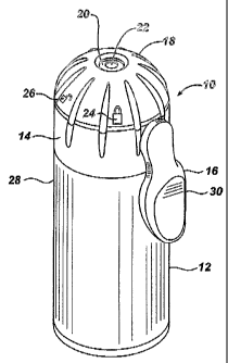
Fig. 1 is a perspective view of a hand-held pressurized product dispenser.
Fig. 2 is an elevation of the Fig. 1 dispenser.

Fig. 3 is an exploded perspective view of some of the components of the
Fig. 1

dispenser.

Fig. 4 is a top view of the Fig. 1 dispenser with a dome of the dispenser
removed.

Fig. 5 is a partial vertical sectional view of the Fig. 1 dispenser.
Fig. 6 is a bottom view of a nozzle of the Fig. 1 dispenser.

Fig. 7 is plan view of a base of the Fig. 1 dispenser.
Fig. 8 is a top view of the Fig. 1 dispenser.

Referring to Figs. 1 and 2, dispenser 10 includes can 12 including a
product under pressure, base 14 secured to the top of can 12, side lever 16,
dome 18, and
nozzle 20 having nozzle orifice 22 therein for discharging the product when
lever 16 is

activated. Can 12 includes a valve mechanism at the top that is actuated by
depressing
discharge tube 23 (shown in phantom in Fig.2). Dome 18 is snap fit onto base
14. Dome
18 is rotatable between a locked position, indicated by indicia 24, in which
dispenser 10 is
prevented fiom discharging product, and an unlocked position, indicated by
indicia 26, in
which dispenser 10 is able to discharge product. Side lever 16 has a lever
airn portion 30
that extends along the side of the can 12. In operation, the user holds
dispenser 10 with


CA 02518483 2005-09-07
WO 2004/087532 PCT/US2004/008769
-4-
hand engageable portion 28 of the can and lever ai7n portion 30 between the
thumb and
fingers.

RefeiTing to Figs. 3 to 5, it is seen that nozzle 20 has a tubular poi-tion 32
that extends along axis 33 and an annular platform 34 at its base. Side lever
16 has a

ring-shaped poi-tion 36 that suiTounds tubular portion 32 and rests on annular
platform 34.
Side lever 16 is pivotally connected to base 14 for pivoting about axis 38 via
projections
39 at end 40 of side lever 16 that engage slots 41 (Fig. 7) in base 14. Nozzle
20 has an
internal tube (not shown) for interacting with delivery tube 23 (Fig. 2) of
the valve
deliveiy mechanism, to depress tube 23 and direct product discharged from tube
23 to
nozzle orifice 22. The upper end of tubular portion 32 has four slots 42 that
open outward
extend a short distance along the length. Dome 18 has four inwardly directed
vanes 44
(shown in Fig. 4 at sectioned portion of nozzle 20) that sit within respective
slots 42.
Vanes 44 interact with slots 42 to transmit rotation of dome 18 to nozzle 20.

Referring to Figs. 5 to 7, nozzle 20 has four downwardly directed feet 46
underneath platfoi7n 34 that rest on a solid portion of upwardly directed
surface 48 of base
14 when nozzle 20 is in a locked position. On Fig. 7, the position 50 for a
foot 46 in the
locked position is shown in phantom. Surface 48 has four openings 52 through
it for
receiving respective feet 46 when nozzle 20 is in the unlocked position. On
Fig. 7, the
position 54 for a foot 46 in the unlocked position is shown in phantom aligned
with an

opening 52. Four upwardly-directed projections 56 are located on one side of
each
opening 52 to prevent a foot 46 fi=om moving beyond the locked position 50
into the
nearby opening 52. Platfoim 34 has recesses 58 ori one side of each foot 46 to
receive
projections 56 when feet 46 are aligned with and moving into openings 52.

RefeiTing to Fig. 8, dome 18 has two internal doine stops 60, 62 that engage
with base stop 64 on base 14 to limit rotation of dome 18 between the locked
and
unlocked positions.

When not in use, dispenser 10 can be move to the locked position by
rotating dome 18 clockwise until dome stop 60 (Fig. 8) contacts base stop 64.
At the
same time, nozzle 20 will be rotated, owing to interaction of vanes 44 in
slots 42, until all
four feet 46 of nozzle 20 reach the locked position 50 (only one position 50
shown on
Fig. 7) adjacent to projections 56. Because feet 46 overlie surface 48 in this
position, they


CA 02518483 2005-09-07
WO 2004/087532 PCT/US2004/008769
-5-
prevent downward movement of nozzle 20 and accidental discharge of product.
When it
is desired to use dispenser 10, the user rotates dome 18 counterclockwise
until dome stop
62 contacts base stop 64. At this time feet 46 are aligned with openings 52
(see position
54 for one foot 46 in Fig. 7). In this position, the spring action of the tube
23 of the valve

deliveiy mechanism of can 12 still biases nozzle 20 upward. However, because
feet are
aligned with openings 52, they are free to move downward into openings 52 when
lever
16 is depressed and ring-shaped portion 36 inoves downward, to activate
discharge of the
valve deliveiy mechanism and axial deliveiy of product fi om nozzle orifice
22.

Representative Drawing
A single figure which represents the drawing illustrating the invention.
Administrative Status

For a clearer understanding of the status of the application/patent presented on this page, the site Disclaimer , as well as the definitions for Patent , Administrative Status , Maintenance Fee  and Payment History  should be consulted.

Administrative Status

Title Date
Forecasted Issue Date 2008-09-23
(86) PCT Filing Date 2004-03-23
(87) PCT Publication Date 2004-10-14
(85) National Entry 2005-09-07
Examination Requested 2005-09-07
(45) Issued 2008-09-23
Deemed Expired 2011-03-23

Abandonment History

There is no abandonment history.

Payment History

Fee Type Anniversary Year Due Date Amount Paid Paid Date
Request for Examination $800.00 2005-09-07
Registration of a document - section 124 $100.00 2005-09-07
Application Fee $400.00 2005-09-07
Maintenance Fee - Application - New Act 2 2006-03-23 $100.00 2005-09-07
Registration of a document - section 124 $100.00 2007-02-09
Maintenance Fee - Application - New Act 3 2007-03-23 $100.00 2007-03-08
Maintenance Fee - Application - New Act 4 2008-03-25 $100.00 2008-03-06
Final Fee $300.00 2008-07-08
Maintenance Fee - Patent - New Act 5 2009-03-23 $200.00 2009-03-02
Owners on Record

Note: Records showing the ownership history in alphabetical order.

Current Owners on Record
THE DIAL CORPORATION
Past Owners on Record
GROH, DAVID M.
O'CONNOR, WILLIAM T.
THE GILLETTE COMPANY
TROTTA, ROBERT
Past Owners that do not appear in the "Owners on Record" listing will appear in other documentation within the application.
Documents

To view selected files, please enter reCAPTCHA code :


To view images, click a link in the Document Description column. To download the documents, select one or more checkboxes in the first column and then click the "Download Selected in PDF format (Zip Archive)" or the "Download Selected as Single PDF" button.

List of published and non-published patent-specific documents on the CPD .

If you have any difficulty accessing content, you can call the Client Service Centre at 1-866-997-1936 or send them an e-mail at CIPO Client Service Centre.


Document
Description 
Date
(yyyy-mm-dd) 
Number of pages   Size of Image (KB) 
Claims 2007-12-07 3 147
Description 2007-12-07 5 243
Drawings 2005-09-07 5 69
Claims 2005-09-07 5 240
Abstract 2005-09-07 2 75
Description 2005-09-07 5 271
Representative Drawing 2005-09-07 1 12
Cover Page 2005-12-09 1 45
Representative Drawing 2008-09-12 1 10
Cover Page 2008-09-12 2 50
Assignment 2005-09-07 10 275
PCT 2005-09-07 13 530
Assignment 2007-02-09 3 90
Prosecution-Amendment 2007-06-07 3 93
Prosecution-Amendment 2007-12-07 7 340
Correspondence 2008-07-08 1 30