Note: Descriptions are shown in the official language in which they were submitted.
CA 02518497 2011-11-08
INTERVENTIONAL CATHETERS HAVING
DIFFERENTIAL CUTTING SURFACES
Field of the Invention
The present invention relates to systems for removing material, such as
obstructions
and partial obstructions, from an internal lumen or cavity of a mammalian
subject, such as a
blood vessel, a portion of the gastrointestinal tract, dural spaces associated
with the spinal
cord, and the like. More particularly, the present invention relates to
interventional catheters
having advanceable, rotatable operating heads incorporating differential
cutting surfaces.
Background of the Invention
Removal of disease such as atherosclerotic plaque, thrombus, and other types
of
obstructions and partial obstructions from internal body lumens or cavities is
a well-
established interventional technique. Numerous interventional catheters have
been conceived
and developed. Most of these systems require placement of a guiding catheter
and guide wire
prior to introduction of the interventional catheter and placement of the
interventional catheter
at the target operating site. Advanceable, rotating operating heads have been
used to cut
and/or ablate obstructions. Many of these prior art systems incorporate
aspiration systems to
remove the ablated material from the site.
Despite the many and varied approaches to the material removal systems, many
challenges remain in providing systems for removing material from a lumen,
such as a blood
vessel, safely and reliably and without causing complications. The safety and
reliability of
the system is manifestly critical. Recovery of debris generated during a
material removal
operation, or maceration of the debris to a particle size that will not
produce blood vessel
damage or embolic events is essential. The flexibility and size of an
interventional catheter is
also an important feature. The system must be small enough and flexible enough
to navigate
through sometimes tortuous internal structures and passageways, such as blood
vessels, for
placement at the target interventional site. The interventional catheter must
also have
1
CA 02518497 2005-09-08
WO 2004/080345 PCT/US2004/007531
sufficient stiffness and integrity to operate reliably at high rotational
rates while allowing for
aspiration and/or infusion of fluids to the site.
In interventional catheters that employ a "cutting head," any cutter
structures must be
benign during navigation of the operating head to and from the interventional
target site, yet
effectively remove material during the operation. In addition, cutter
structures must
effectively remove disease or undesired material without damaging delicate
neighboring
tissue, such as blood vessel walls or other healthy tissue, which often
surrounds and may be
attached to the undesired material. Thus, it is important for cutter
structures of interventional
catheters to accurately and reliably differentiate between the disease or
undesired material
and healthy tissue.
Cutter assemblies operating according to the principles of differential
cutting have
been developed. Differential cutting blades exert high shear forces against
relatively hard
substrates to cut or ablate relatively hard, inelastic material. Softer,
elastic structures, such as
healthy tissue, blood vessel walls, and the like are deformed rather than cut
by differential
cutting blades, which reduces the shear forces and protects elastic structures
from damage.
Less elastic material does not deform when contacted by a differential cutting
blade, and
shear stresses are consequently exerted on less elastic material to out or
scrape and ablate the
material without damaging elastic tissue in proximity. In this manner,
fragments of diseased,
undesirable material are removed by differential cutting blades, while the
more elastic,
healthy tissue remains undamaged.
U.S. Patent 4,445,509 describes differential cutting in the context of an
atherectomy
device. This patent describes a cutter assembly having a plurality of cutting
flutes, each
cutting flute having a blade surface operating according to the principle of
differential
cutting. The flute density and blade cant angle are disclosed as being key to
providing
effective differential cutting. Specifically, the cant angle, or angle of
intersection of the
cutting face and the circumference at the point of contact with the tissue is
at least 90 and
preferably about 110 . The face of the cutting flute also has a slight concave
curvature.
Some i nterventional catheters use diamond grit o n a cutting surface i n an
effort t o
provide highly divided, small particle size debris. D iamond grit p articles,
however, don't
operate as differential cutters because, depending on their orientation on the
cutting surface,
their exposed surfaces form random cant angles, or angles of attack, to
produce different
cutting characteristics at different points of contact with tissue. Because
not all of the
diamond grit surfaces operate as differential cutting mechanisms, the diamond
grit is more
likely to damage elastic, healthy tissue such as blood vessel walls.
2
CA 02518497 2011-11-08
The extent and consistency of the disease or undesired material forming an
obstruction
are frequently not well characterized prior to intervention. Thus, although
interventional
catheters and cutter assemblies having different sizes and material removal
properties may be
provided, and may even be interchangeable on a material removal system, it is
difficult to
ascertain which combination of features will be most effective in any
particular intervention
prior to insertion of the device. Various quick-connect systems have been
developed to
permit removal and installation of multiple operating catheters during a
single surgical
intervention. This is not ideal, since interchange, withdrawal and insertion
of multiple
interventional catheters is time consuming, may result in increased blood loss
during the
intervention, and increases the risk of the operation. Having access to
multiple cutter
assemblies having different sizes and different material removal properties on
a single
interventional operating catheter is highly desirable.
In particular, it is desirable to use an interventional catheter having a
small diameter
during the catheter insertion and removal routine and having a cutter assembly
that expands to
provide a larger diameter cutter during operation when located at the target
site. Numerous
expandable cutter assemblies for interventional catheters have been developed.
The
following U.S. Patents disclose various approaches to expandable cutter
assemblies:
6,565,588B1; 5,540,707; 5,192,291; 5,224,945; 5,766,192; 5,158,564; 4,895,560;
5,308,354;
5,030,201; 5,217,474; 5,100,425; and 4,966,604.
3
CA 02518497 2011-11-08
Summary of Invention
Various embodiments of this invention provide an interventional catheter
assembly
comprising:
a. a rotatable drive shaft in operable communication with a drive system; and
b. a dual differential cutter assembly comprising:
(i) a fixed blade cutter assembly comprising at least one fixed differential
cutting surface having a cant angle of less than 90 , the cant angle being an
angle of intersection of the cutting surface and a line tangent to the
circumference of the cutter assembly; and
(ii) an adjustable blade cutter assembly comprising a plurality of adjustable
blades.
Interventional catheters of the present invention incorporate a material
removal
component, referred to herein as a "cutter" or "cutter assembly" or "operating
head" at their
distal ends. The cutter assembly is operably connected to a rotatable and
axially translatable
drive shaft and catheter system, drive system, and control systems. The
"cutter assembly"
comprises one or more distally located cutting or abrading surface(s), or
blades, that operates
according to the principles of differential cutting. The cutting surfaces or
blades are
preferably substantially rigid and multiple blades or cutting surfaces are
preferably radially
symmetrical. The differential cutting surfaces or blade(s) have one or more
beveled edges
having a cant angle, or angle of attack, of less than 90 to provide effective
differential
cutting.
As used herein in the description of various components, "proximal" refers to
a
direction toward the system controls and the operator along the path of the
drive shaft and
catheter system, and "distal" refers to the direction away from the system
controls and the
3a
CA 02518497 2005-09-08
WO 2004/080345 PCT/US2004/007531
operator along the path of the drive shaft and cathetei system toward or
beyond a terminal
end of the cutter assembly. In general, interventional catheters of the
present invention
comprise a cutter assembly comprising at least one differential cutting
surface positioned at
or near the distal end of the interventional catheter system.
Although the "cutting" surfaces or b lades o f i nterventional catheters o f
the p resent
invention may be sharp and may actually "cut" material at the target site, the
term "cut" or
"cutting," as used herein, refers to cutting, scraping, ablating, macerating
and otherwise
breaking down undesired material into removable p articles or smaller,
removable units of
material. " Cutters," " cutter a ssemblies," " cutting surfaces" and "blades"
likewise refer to
structures for cutting, scraping, ablating, macerating and otherwise breaking
down material
into smaller pieces.
Cutter assemblies of the present invention may comprise at least one
differential
cutting surface, and generally comprise a plurality of differential cutting
blades. A cutter
assembly may have fixed and/or adjustable blades. In one embodiment, a fixed
blade cutter
assembly comprises a plurality of differential cutting blades and a plurality
of generally large
aspiration ports formed between neighboring differential cutting blades.
Although the
differential cutting surfaces on the fixed blade cutter assembly are not
adjustable, the fixed
blade cutter assembly may provide a range of cutting diameters as a
consequence of the
generally ovoid or conical external profile of the cutter assembly. In another
embodiment, a
plurality of pivotable differential cutting blades are incorporated in an
expandable cutter
assembly that is navigable to the intervention site in a smaller diameter
condition, then
adjusted to a larger diameter condition at the target site during operation,
and finally
withdrawn from the intervention site in a smaller diameter condition. In
another
embodiment, cutter assemblies of the present invention incorporate both fixed
differential
cutting blades and pivotable differential cutting blades in a dual or
composite cutter
assembly.
The drive s haft that c onveys rotation and torque from a drive system to the
cutter
assembly must be small enough and flexible enough to be navigated through
small and
tortuous passageways during navigation of the cutter assembly to the target
removal site, and
must have sufficient mechanical integrity to transfer high rotational and
torque loads and
operate in a high vacuum, aspirate withdrawal environment. Multi-filar helical
coils are used
as drive shafts in many types of interventional catheters having a rotatable
operating head.
Several preferred drive shaft embodiments are described below.
4
CA 02518497 2005-09-08
WO 2004/080345 PCT/US2004/007531
Interventional catheters of the present invention preferably include an
aspiration
system for removal of debris from the intervention site, generally via
aspiration through one
or more material removal ports provided in the cutter assembly or another
component in
proximity to the cutter assembly. Debris generated during a material removal
operation is
entrained in fluids (e.g. blood), and the aspirate fluid containing debris is
removed by
aspiration through the material removal ports and withdrawn through a sealed
lumen of the
interventional catheter. The sealed lumen is connectable to a vacuum source
and aspirate
collection system. The material removal ports may be disposed between blade
surfaces of the
cutter assembly and preferably have a large surface area.
Liquid infusion may be provided in proximity to the cutter assembly in
addition to or
alternatively to aspiration. Infusion of liquids may be used to provide
additional liquid
volume for removal of debris, or to deliver lubricating fluids, treatment
agents, contrast
agents, and the like. Infusion of fluids in proximity to the area of a
material removal
operation maybe desirable because it tends to reduce the viscosity of the
materials being
removed, thus facilitating removal through relatively small diameter lumens.
Infusion of
liquids also desirably tends to reduce the volume of blood removed during a
material removal
operation. According to one embodiment, a sealed lumen formed between the
cutter
assembly drive shaft and a catheter may alternatively and selectively be used
as aspirate
removal system and an infusion system. The sealed lumen may thus be
selectively
connectable to a vacuum source and aspirate collection system for aspiration,
and an infusion
source for infusion of liquids. Ports in or in proximity to the cutter
assembly may be thus be
employed, selectively, as aspiration and infusion ports.
Interventional catheters of the present invention may also incorporate an
articulating
bearing that improves the flexibility of the system and facilitates navigation
of the cutter
assembly through tortuous passageways during guidance to and from the
intervention site.
The bearing system couples cutter assemblies and operating heads of the
present invention to
the drive s haft so t hat torque and rotation are c onveyed from the d rive s
haft t o the cutter
assembly. The bearing system also couples the cutter assembly or operating
head to a static
catheter system, or sheath, that provides a sealed lumen and generally does
not rotate during
operation of the interventional catheter. The bearing system provides enhanced
flexibility at
the connection that joins the operating head, drive shaft and c atheter, and
also provides a
channel for aspiration and/or infusion of fluids.
CA 02518497 2005-09-08
WO 2004/080345 PCT/US2004/007531
Brief Description of the Drawings
Figure 1 shows exemplary components of an interventional catheter assembly of
the
present invention having an operating head comprising differential cutting
surfaces and an
articulating bearing.
Fig. 2 shows a prior art differential cutter assembly described in U.S. Patent
4,445,509, wherein the differential cutter blades have cant angles of greater
than 90 .
Figure 3A shows an enlarged side view of an exemplary fixed blade cutter
assembly
of the present invention having a plurality of differential cutting surfaces
and aspiration ports.
Figure 3B shows an enlarged perspective view of the fixed blade differential
cutter
assembly of Figure 3A.
Figure 3C shows an enlarged cross-sectional view of the fixed blade
differential cutter
assembly of Figures 3A and 3B illustrating differential cutting surfaces
having cant angles of
less than 90 .
Figures 4 A and 4B show schematic diagrams illustrating the effect on a
relatively
elastic surface of a differential cutting surface having a 90 cant angle
(Fig. 4A) as used in
prior art devices and a differential cutting surface having a 60 cant angle
(Fig. 4B) as used in
cutter assemblies of the present invention.
Figures 5A and 5B illustrate schematic cross-sectional views of differential
cutter
assemblies of the present invention having three differential cutting surfaces
(Fig. 5A) and six
differential cutting surfaces (Fig. 5B).
Figures 6A and 6B illustrate another embodiment of a fixed diameter cutter
assembly
having a plurality of differential cutting surfaces. Fig. 6A shows a schematic
isometric view
of the cutter assembly and Fig. 6B shows a schematic distal end view of the
cutter assembly.
Figures 7A and 7B illustrate schematic distal and proximal end views,
respectively, of
another embodiment of a fixed blade cutter assembly of the present invention
having a
plurality of differential cutting surfaces.
Figures 8A and 8B illustrate additional types of cutter blades of the present
invention
incorporating differential cutting surfaces.
Figures 9A and 9B show enlarged schematic diagrams of a composite cutter
assembly
of the present invention comprising two types of differential cutter surfaces
in a dual cutter,
with the proximal end of the cutter assembly mounted to an articulating
bearing. Figure 9A
shows the differential cutter and bearing assembly in an assembled condition,
while Figure
9B shows the differential cutter and bearing assembly in an exploded,
unassembled condition.
6
CA 02518497 2005-09-08
WO 2004/080345 PCT/US2004/007531
Figures 1 OA and 1 OB are fluoroscopic x-ray images o f a coronary artery
having a
removal site, wherein Figure 10A depicts the nearly totally and diffusely
occluded artery
before the operation of the removal system and Figure 10B depicts a cleared
artery after use
of the interventional catheter assembly of the present invention.
Figures 11A-11C show the results of operation of cutter assemblies having
various
characteristics in a laboratory stained bovine aorta model as described in
Example 2. Figure
11 A shows damage done to the bovine aorta after operation of a cutter
assembly having a
plurality of cutting surfaces having a cant angle of 90 . Figure 11B shows
damage done to
the bovine aorta after operation of a cutter assembly having randomly oriented
diamond grit
particles on an outer, operating surface. Figure 11 C shows the results of
operation of a cutter
assembly having a plurality of differential cutting surfaces having a cant
angle of 60 and
demonstrates that the bovine aorta was not damaged with this cutter assembly.
Figures 12A-12F s how the results of operation of cutter assemblies having
various
characteristics in porcine blood vessels as described in Example 3.
Detailed Description of Preferred Embodiments
Exemplary interventional catheters and material removal systems, components
and
subassemblies suitable for use in connection with components of the present
invention are
disclosed and described in the publications incorporated herein by reference,
including U.S.
Patent 6,565,588B1 and PCT Patent Publication WO 01/76680. The cutter
assemblies and
bearing assemblies described herein may be used with interventional catheters
having a
variety of drive, control and other systems. The cutter assembly is provided
at or near a
distal end of the interventional catheter and is guided to and from a desired
material removal
site through internal passages, such as blood vessels, as is well known in the
art. At the target
removal site, the cutter assembly is actuated to cut, grind or ablate, or
otherwise separate and
break down undesired occlusive material. In many embodiments, the occlusive
material is
removed the site by means of an aspiration system or another debris removal
system.
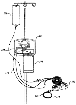
Figure 1 illustrates an exemplary interventional catheter and operating system
of the
present invention. In the interventional catheter and control system shown in
Fig. 1, console
unit 102 is provided for housing certain power, control and display functions.
Console 102
may have adjustable controls that permit the operator to adjust operating
parameters of the
interventional catheter. Control features may include a system on/off
actuator, selectable
torque buttons to adjust cutter assembly rotational torque, selectable
rotation features
providing fixed and/or variable rotational speeds during actuation of the
cutter assembly, a
7
CA 02518497 2005-09-08
WO 2004/080345 PCT/US2004/007531
display of the real-time rotational speed of the cutter assembly during
actuation, a timer
control and/or actuation time counter to display the length of time of actual
cutter operation, a
motor only control to activate or shut off a rotational drive system without
affecting
aspiration and/or infusion, an aspiration and/or infusion only control to
activate or shut off an
aspiration and/or infusion function without affecting the rotational drive,
and the like.
In the embodiment of Fig. 1, aspiration or vacuum motor 104 is mounted on or
in
console 102, as is a liquid/debris collection receptacle 106 and a liquid
supply 108. Power
connector 110 provides power to other interventional catheter components.
Suitable
electrical and liquid flow conduits are provided for operable communication
between console
102 and catheter control module 112. Control module 112, in this embodiment,
houses the
motor drive for rotating a cutter assembly of the interventional catheter and
also incorporates
certain connectors and systems for communicating torque and rotation to a
drive shaft having
an operating head, such as a rotatable cutter assembly, mounted at or near its
distal end, and
for facilitating liquid infusion to and/or liquid and debris removal from the
operating head.
Control module 112 also incorporates systems facilitating axial translation of
the
interventional catheter, indicated generally at 114, and an operating head
116, such as a
rotatable, advanceable cutter assembly having at least one differential
cutting surface, to and
from an internal target material removal site. An articulating bearing,
described herein, may
be incorporated in proximity to the operating head to provide greater
flexibility at the distal
portion of the interventional catheter.
In the interventional catheter system illustrated in Fig. 1, certain power,
control and
display functions are provided separately in console 102 and catheter control
module 112. It
will be recognized that these power, control and display functions may be
provided in a
single unit, or may be separated in a plurality of control units. Likewise, it
will be recognized
that the cutter assemblies and differential cutting surfaces of the present
invention may be
incorporated in interventional catheters having different types of power,
display and control
systems, and providing different functions. Differential cutting surfaces of
the present
invention may be incorporated in any type of interventional catheter that may
be employed
for removal of undesired material located within a human or animal body.
The operating head of the interventional catheter of the present invention may
comprise any of a variety of cutting devices or assemblies having one or more
stiff and/or
sharp cutting surface(s) for cutting, fragmentizing, pulverizing, ablating,
scraping, grinding or
otherwise reducing the size of and/or separating undesired material from
healthy tissue, such
as the walls o f a blood vessel, in proximity to the target removal site. For
example, the
8
CA 02518497 2005-09-08
WO 2004/080345 PCT/US2004/007531
cutting surfaces may include one or a combination of blade(s), spring(s),
metallic or ceramic
or composite surfaces having at least one surface that operates according to
the principle of
differential cutting.
Some exemplary materials of construction for the cutting surface(s) of the
cutter
assembly include metals, metal alloys, ceramics and cermet materials, such as
but not limited
to, various types of stainless steels, such as series 300 and/or 400, vanadium
steel, nickel-
titanium, titanium, titanium-containing metals and oxide ceramics. Metallic
materials such as
stainless steels may be hardened using well-known techniques. In general,
cutter surfaces are
constructed from hard materials and may be treated to impart even greater
hardness to the
cutter surfaces. Cutter surfaces constructed from a material that is harder
than the materials
used to construct stents are generally provided. The cutter assembly, or sub-
components
thereof, such as the cutting surfaces, may b e coated with a r adio-opaque
material such as
gold, platinum, inks and the like, to render the expandable cutter assembly
radioscopically
visible and to assist a medical professional in guiding and positioning the
cutter assembly
relative to an occlusion.
Fig. 2 illustrates an enlarged cross-sectional view of prior art differential
cutter
surfaces according to U.S. Patent 4,445,509 (hereinafter referred to as " `509
patent"). A
plurality of cutting flutes 14 are provided with corresponding cutting faces
18. Fluid ports 15
are provided as passageways having a rearward or longitudinal component and
are intended
for withdrawal of fluids and debris from the intervention site to cavity 40.
The cutter
assembly, as illustrated, rotates in a clockwise direction during a material
removal operation.
The cant angle, which is illustrated as angle a, is the angle of intersection
of cutting face 18
and the circumference C, or a line tangent to circumference C of the cutter
assembly.
According to the `509 patent, cant angles of about 110 , and cant angles
deviating from 110
by about 20 provide acceptable differential cutting properties.
Figs. 3A-3C illustrate fixed blade cutter assemblies having a plurality of
differential
cutting surfaces according to the present invention. Cutter assembly 50
comprises a plurality
of cutter blades 52 arranged in a radially symmetrical arrangement with
respect to a central
longitudinal axis of the cutter assembly. Each of the cutter blades 52 is
joined at a distal end
to form a distal bore 54 which serves as a rotating bearing for a guidewire
when a guidewire
is used in a material removal operation. Cutter blades 52 may alternatively
terminate at their
distal ends in a blunt or pointed structure without forming a distal bore in
cutter assemblies
that are employed without guidance over a guidewire. Cutter blades 52
terminate at their
proximal ends in a proximal ring-like collar 55 that is mounted to a drive
shaft, a catheter
9
CA 02518497 2005-09-08
WO 2004/080345 PCT/US2004/007531
system, or an intermediate bearing structure providing operable connections
between the
cutter assembly, the drive shaft, and the catheter system.
The overall outer configuration of cutter assembly 50 is generally round from
an axial
view and oblong or frusto-conical from a profile view. The outer edges of
cutter blades 52
taper along a curved line between a smaller diameter distal bore 54 and a
larger diameter
proximal collar 55. This configuration allows the smaller diameter distal end
of the cutter
assembly to penetrate an obstruction or partial obstruction and, as the cutter
assembly is
advanced through the obstruction, a progressively larger bore is provided as
the diameter of
the cutter assembly increases toward its distal end. The inside curved profile
of the blade
contour generally corresponds to the outer curved contour of the blade. In
many
embodiments, cutter blades 52 have a generally constant chord between proximal
collar 55
and distal bore 54, providing a strong, yet thin blade.
Ports 68 formed by the boundaries of neighboring pairs of cutter blades 52 and
the
distal and proximal rings are large and generally triangular in configuration,
having curved
sides. Ports 68 provide access to an internal space and aspiration lumen for
removal of fluids
and debris during a material removal operation. Because cutter blades
incorporating
differential cutting surfaces of the present invention can be provided as thin
blades, the port
size can be maximized. The total cross-sectional area of the ports, compared
to the total
cross-sectional of the inside surfaces of the cutter blades in cutter
assemblies of the present
invention is generally at least 1.5:1, preferably at least 2:1, more
preferably at least 2.5:1; and
more preferably yet at least 3:1.
Each of the cutter blades 52 has a differential cutter surface 56 that
contacts material
to be removed when cutter assembly 50 is rotated during a material removal
operation. In the
cutter assembly embodiment shown in Figs. 3A-3C, cutter assembly 50 is
configured to
rotate in a counterclockwise direction. Differential cutter surfaces of the
present invention
have a cant angle a, which is the angle of intersection of cutter surface 56
and a line tangent
to the circumference of the cutter assembly, of less than 90 . In some
embodiments of cutter
surfaces of the present invention, the cant angle is less than 80 ; in other
embodiments of
cutter surfaces of the present invention, the cant angle is less than 70 ; in
yet other
embodiments of cutter surfaces of the present invention, the cant angle is
less than 60 ; in
alternative embodiments of cutter surfaces of the present invention, the cant
angle is less than
50 ; in still other embodiments of cutter surfaces of the present invention,
the cant angle is
less than 40 . The cant angle is generally greater than 15 , may be greater
than 25 , and is
often greater than 30 or 40 .
CA 02518497 2005-09-08
WO 2004/080345 PCT/US2004/007531
Differential cutter surfaces may be optimized for use in different types of
cutting
environments, for different types of materials being removed, and for
different applications,
by providing different cant angles, providing that the cant angle for
differential cutting is less
than 90 . B ecause differential cutter surfaces having cant angles o f 1 ess
than 9 0 provide
more effective differential cutting, fewer cutter surfaces may be required for
material removal
operations. In general, in cutter assemblies having fewer blades, the blades
have a thin cross-
sectional dimension, allowing for larger aspiration ports and greater
aspiration efficiency.
Cutter assemblies of the present invention are benign to healthy, elastic
tissue while
providing effective removal of less elastic, disease tissue and providing high
aspiration rates
for removal of debris.
Cutter surfaces 56 may b e provided o n a leading blade s urface 5 8 t hat i s
a planar
surface. Trailing blade surfaces 60 may comprise a compound surface composed
of two or
more adjoining surfaces 62 and 64 provided at angles to one another. In the
embodiment
shown in Figs. 3A-3C, leading blade surfaces 58 are longer than trailing blade
surfaces 60,
and leading blade surfaces 58 intersect trailing blade surfaces 60 at an inner
region at a
substantially right angle. The outer terminal edges 66 of blades 52 formed at
the intersection
of cutter surfaces 5 6 and trailing blade surfaces 6 0 preferably form an
acute angle t o one
another and are preferably sharpened. In many embodiments of cutter assemblies
of the
present invention, neither the leading nor the trailing blade surfaces are
aligned radially with
respect to the longitudinal axis of the cutter assembly.
Figure 4 illustrates, schematically, the cutting action of a blade 70 having a
90 cant
angle rotating in a counterclockwise direction (Fig. 4A) and the cutting
action of a blade 71
having a 60 cant angle rotating in a counterclockwise direction (Fig. 4B).
Differential
cutting blade 71 having a 60 cant angle, as shown in Fig. 4B, is gentle and
benign when it
contacts a resilient surface, yet it effectively cuts and abrades less
resilient materials to
provide effective removal of disease material such as plaque, calcified
material and thrombus.
Cutting blade 70 having a 90 cant angle, as shown in Fig. 4A, can be quite
damaging to
resilient surfaces. The laboratory tests described in Example 2, below,
provide data
confirming the improved properties of cutting blades having a 60 cant angle
compared to
cutting blades having a 90 cant angle.
Figures 5A and 5B illustrate cutter assemblies having different numbers and
arrangements of differential cutting surfaces. Any number of cutter blades may
be employed
in cutter assemblies and interventional catheters of the present invention.
Cutter assemblies
11
CA 02518497 2005-09-08
WO 2004/080345 PCT/US2004/007531
having three, five, six and seven cutter blades that are radially symmetrical
are e specially
preferred for many applications.
Fig. 5A shows a cutter assembly 72 having three radially symmetrical cutter
blades 74
that provide differential cutting when cutter assembly 72 is rotated in a
clockwise direction.
Cutter blades 74 terminate at a distal end in distal bore 75 and terminate at
a proximal end in
proximal collar. Cutter surfaces 77 have a cant angle a of less the 90 .
Cutter surfaces 77
are provided on a leading blade surface 78 that is a planar surface. Trailing
blade surfaces 79
have a tapered configuration. In the embodiment shown in Fig. 5A, leading
blade surfaces 78
are longer than trailing blade surfaces 79, and leading blade surfaces 78
intersect trailing
blade surfaces 79 at an inner region at an obtuse angle.
Fig. 5B shows an embodiment of cutter assembly 80 having six radially
symmetrical
cutter blades 82 that provide differential cutting when cutter assembly 80 is
rotated in a
clockwise direction. Cutter blades 82 terminate at a distal end in distal bore
83 and terminate
at a proximal end in proximal collar. Cutter surfaces 85 have a cant angle a
of less the 90 .
Cutter surfaces 85 are provided on a leading blade surface 86 that is a planar
surface.
Trailing blade surfaces 87 have a tapered or compound configuration. In the
embodiment
shown in Fig. 5B, leading blade surfaces 86 intersect trailing blade surfaces
87 at an inner
region at an acute angle.
Figures 6A and 6B illustrate yet another cutter assembly 120 having a
plurality of
cutting blades 122, each cutting blade being provided with a differential
cutting surface 124.
Cutter assembly 120 has seven cutter blades provided in a radially symmetrical
arrangement
with ports 125 provided between each neighboring pair of cutter blades. Ports
125 are large
and have a generally ovoid configuration with curved walls. Cutter assembly
120 is rotatable
in a clockwise direction to provide differential cutting.
Cutter blades 122 terminate at a distal end in distal bore 126 and terminate
at a
proximal end in proximal collar 128. Cutter surfaces 124 have a cant angle a
of less the 90 .
Cutter surfaces 124 are provided on a leading blade surface 131 that is a
planar surface.
Trailing blade surfaces 130 have a tapered or compound configuration. In the
embodiment
shown in Figs. 6A and 6B, edges 129 of cutter surfaces 124 at their largest
diameter point
extend beyond the diameter of proximal collar 128. Edges 129 have a curved
profile along
their length between distal bore 126 and proximal collar 128 that extends to a
larger diameter
than proximal collar 128 and then tapers to join proximal collar 128. This
cutter blade profile
permits effective removal of material to form a passageway through
obstructions that is larger
in diameter than the proximal collar of the cutter assembly and promotes side
cutting. This
12
CA 02518497 2005-09-08
cutter blade profile may be particularly advantageous for use in
interventional catheter
systems in which the cutter assembly is guided by remote steering technologies
rather than
being advanced on a guidewire.
Figures 7A and 7B illustrate yet another c utter assembly 140 having a
plurality of
differential cutting blades 142 and aspiration ports 143. In this embodiment,
both leading
blade surfaces 144 and trailing surfaces 146 p rovide-differential cutting
surfaces and both.
leading and trailing blade surfaces may be compound surfaces. Leading blade
surfaces 144
form differential cutting surfaces 145, while trailing blade surfaces 146 form
differential
cutting surfaces 147. Differential cutting surfaces 145 and 147 all have cant
angles of less
than 90 to provide effective an'T safe differential cutting properties.
Differential cutting surfaces 145 and 147 operate when cutter assembly 140 is
rotated
in clockwise and counterclockwise directions, respectively. Providing
differential cutting
surfaces on both the leading and trailing surfaces of cutting blades
dramatically increases the
versatility of the cutter assembly when it is used in conjunction with a bi-
directional motor
drive. In preferred embodiments, differential c utting surfaces 145 and 147
have different
cant angles to provide different differential cutting properties. Differential
cutting surfaces
145 may have a cant angle of less than 90 and more than about 70 , while
differential cutting
surfaces 147 may have a cant angle of less than 70 and more than 300. The
operator may
select the direction of drive shaft and cutter assembly rotation to employ the
differential
cutter blades having the differential cutting properties most suitable for
removal of particular
material during a material removal process. Various combinations of
differential cutter
blades and differential cutting surfaces having various cant angles may be
used in differential
cutting blades having dual differential cutting surfaces.
The fixed blade cutter assemblies described above have multiple c utter blades
and
multiple differential cutter surfaces. The cutter assemblies and cutter blades
may be provided
in various configurations, presenting various external profiles, and, having
various port
surface area to internal blade surface area ratios. In general, the plurality
of differential
cutting surfaces provided in a cutter assembly having a single differential
cutting surface on
each blade each have the same cant angle. In alternative embodiments,
different cant angles
may be provided on single differential cutting surfaces on individual cutting
blades forming a
cutter assembly. Thus, for example, a fixed blade cutter assembly having six
radially
symmetrical cutter blades may be provided having three cutter blades with
differential cutting
surfaces having a first cant angle less than 90 and three cutter blades with
differential cutting
surfaces having a second cant angle less than 90 and different from the first
cant angle. The
13
CA 02518497 2005-09-08
WO 2004/080345 PCT/US2004/007531
cutter blades having differential cutting surfaces with different cant angles
are preferably
provided in an alternating arrangement.
Figures 8A and 8B illustrate yet additional types of differential cutting
blades 150 and
160 that may be used, for example, as pivoting differential cutting blades in
an expandable
type of cutting assembly, which is described in more detail below.
Differential cutting blade
150 comprises a generally planar surface 152 having a differential cutting
surface 154 at a
peripheral edge. Planar surface 152 may be mounted on or integral with
mounting tabs or
rods 156 for mounting blades 150 to a cutter assembly structure. Differential
cutting blade
160 comprises a generally planar surface 162 having a differential cutting
surface 164 at a
peripheral edge and a mounting rod 166 for mounting blades 160 to a cutter
assembly
structure. Differential cutting surfaces 154 and 164 have cant angles, as
defined above, of
less than 90 .
The profile of differential cutting surfaces may be symmetrical, as
exemplified by
differential cutting surface 154 in Fig. 8A or a symmetrical, as exemplified
by differential
cutting surface 164 in Fig. 8B. Asymmetrical cutting surfaces are generally
provided having
a larger diameter profile near the distal face 168 of the cutter blade when it
is assembled in a
cutter assembly, although various asymmetrical surface configurations may be
used. The
differential cutting surfaces are preferably provided substantially along the
peripheral edge of
cutting blades 150 and 160 and may extend over a distal face 168 of cutter
blade 162, for
example. Cutter blades 152 and 162 may have a substantially constant thickness
throughout
their bodies, with diminishing thickness at the differential cutting surfaces
154 and 164,
respectively, forming sharp edges at the cutting surface peripheral edges.
Alternatively,
cutter blades 152 and 162 may have a variable thickness throughout their
bodies and may
continuously or variably taper toward differential cutting surfaces 154 and
164.
The surfaces opposing planar surfaces 152 and 162 (not shown) may be planar
over
their entire surfaces and terminate without tapering in peripheral surfaces
154 and 164.
Alternatively, the opposing surfaces may have differential cutting surfaces in
proximity to
their p eripheral edges t o provide cutter b lades 150 and 160 having dual
differential cutter
surfaces. In a dual differential cutter configuration, cutter blades may
operate as differential
cutting surfaces in either direction of rotation of a drive motor. As
described above, in a dual
differential cutter configuration, opposite cutter surfaces may have different
cant angles, both
less than 90 , to provide enhanced cutter assembly versatility. Although
cutter blades 150
and 160 are illustrated having solid surfaces, and this embodiment is
preferred for many
14
CA 02518497 2005-09-08
WO 2004/080345 PCT/US2004/007531
applications, alternative embodiments may be provided in which cutter blades
150 and 160
have cut-out portions or cavities on their planar surfaces.
Figures 9A and 9B illustrate dual differential cutter assemblies having a
fixed
differential cutter assembly 200, an adjustable differential cutter assembly
210 shown in an
expanded diameter condition in which the blades are in a radial configuration,
and a bearing
250 communicating between the cutter assemblies, the drive shaft, and the
catheter assembly.
Fixed cutter assembly 200 is preferably provided at a distal end of the
assembly, with
adjustable cutter assembly 210 mounted proximally to the fixed cutter
assembly. Suitable
fixed cutter assemblies have been described above. In the embodiment shown in
Figs 9A and
9B, differential cutting blades provided on the fixed cutter assembly and on
the differential
cutter assembly have approximately the same length. In alternative
embodiments, differential
cutting blades on either the fixed or adjustable blade cutter may have
different lengths.
Adjustable diameter differential cutter assembly 210 comprises a plurality of
generally planar cutter blades 212, each having at least one differential
cutting surface 214
extending substantially along a peripheral edge. Differential cutting surfaces
214 have cant
angles of less than 90 , as described in detail above. In general, from three
to seven or more
pivotable differential cutting blades may be provided on adjustable cutter
assembly 210. The
cant angles of differential cutting surfaces 214 may be the same as or
different from cant
angles of differential cutting surfaces provided on fixed differential cutter
assembly 200. In a
preferred embodiment, the cant angles of differential cutting surfaces 214 are
less than the
cant angles of differential cutting surfaces provided on fixed differential
cutter assembly 200.
Mounting rods 216 of cutter blades 212 are pivotably mounted in mating slots
218 of
adjustable cutter support 220 having a central passageway 222 communicating
with a central
bore of the distal cutter and a central bore of bearing assembly 250. Central
passageway 222
generally forms part of an aspiration and/or infusion lumen. Cutter support
220 is configured
to support cutter blades 212 in a tangential position, in which they lie flat
against a support
face to present a smaller diameter profile and in a radial position, in which
they extend
radially to present a larger diameter, differential cutting profile. The
cutter blades may be
adjusted between the tangential and radial orientations by changing the
direction of rotation
of the drive system, or using alternative mechanisms. Aspiration and/or
infusion ports may
be provided in cutter support 220. Additional details concerning the structure
and function of
this type of adjustable cutter assemblies are described in U.S. Patent
6,565,588 B1 and PCT
International Patent Publication WO 01/76680 Al.
CA 02518497 2005-09-08
WO 2004/080345 PCT/US2004/007531
Bearing assembly 250 provides operable coupling of an operating head, such as
dual
cutter assemblies 200 and 210, directly or indirectly to a drive shaft that
transfers torque and
rotation to the operating head. The bearing assembly is also operably coupled,
directly or
indirectly, to a static (non-rotating) catheter system providing a sealed
lumen for aspiration
and/or infusion of liquids. Bearing system 250 articulates to improve the
overall flexibility
and guidability of the operating head as it is navigated to and from the
material removal site
and provides an internal channel for aspiration and/or infusion of liquids
through the bearing
system.
Bearing system 250 comprises an internal shaft 260 coupled, directly or
indirectly, to
the drive shaft at a proximal end 262 and coupled, directly or indirectly, to
the operating head
at a distal end 264. Bearing system 250 additionally comprises a cylindrical
static member
280 provided as an outer sleeve that is fixedly coupled at or near a proximal
end to a distal
end of the catheter system to provide a sealed internal lumen and catheter
system. Internal
shaft 260 and static member 280 are operably coupled by one or more connecting
structures,
such as rods 282 retained in slots 284 formed in static member 280.
Static member 280 is mounted on a peripheral surface of internal shaft 260 so
that
rods 282 are retained in slots 284 and ride in a curved annular seat 266
formed on internal
shaft 260. Curved annular seat 266 has a variable diameter, with a central
smaller diameter
section flaring in both distal and proximal directions to larger diameter
distal and proximal
boundaries 268 and 270, respectively. Rods 282 ride in the curved annular seat
to provide
limited pivoting of internal shaft 260 and the operating head with respect to
static member
280 and the catheter assembly. T he profile and depth of the c urved annular s
eat may b e
adjusted and configured to provide a desired degree of articulation. This
bearing system thus
provides limited articulation of the operating head with respect to the
catheter assembly and
facilitates both navigation of the operating head to and from the target
material removal site,
and operation of the operating head at the target material site to ablate
occlusive material.
Drive shafts for use in interventional catheters of the present invention
generally
comprise helical coil or braided shafts may comprise composite drive shafts
having variable
flexibility and/or torque carrying capability at different sections along
their length. In one
embodiment, a helical coil drive shaft is provided having a less flexibility
and higher torque
carrying capability at a proximal portion and greater flexibility and less
torque carrying
capability at a distal portion. The proximal portion of the drive shaft may
comprise a helical
coil shaft having more files than the helical coil shaft forming the distal
portion of the drive
shaft. In one embodiment, a proximal drive shaft section comprises a tri- or
quad-filar helical
16
CA 02518497 2005-09-08
WO 2004/080345 PCT/US2004/007531
coil, while a distal drive shaft section comprises a bi- or tri-filar helical
coil, respectively. In
a drive shaft having a braided construction, a proximal drive shaft section
comprises more
strands than a distal drive shaft section.
In another embodiment, a proximal drive shaft section comprises a multi-filar
helical
coil in which the adjacent files are closely spaced, while a distal drive
shaft section comprises
a single or multi-filar helical coil in which the adjacent files are spaced
from one another by a
space corresponding to at least the diameter of a file. The spaces may be
greater, depending
on the flexibility and torque-carrying requirements of the distal drive shaft
section. A
preferred drive shaft may comprise a distal section having a helical coil with
spaced apart
files over which a sealing member is installed. The sealing member is
preferably no thicker
than the diameter of a drive shaft file and is constructed from durable,
flexible plastic
materials such as polyfluorotetraethylene (PFTE). A heat shrinkable PFTE tube
may be
installed and shrunk to conform generally to the configuration of the distal
drive shaft spaced
apart files to provide a sealed distal drive shaft lumen, and to improve the
lubricity of the
distal drive shaft section as it is navigated to and from the target material
removal site. The
outer sealed layer may extend a distance of from about 2 cm to about 40 cm
from the distal
end of the drive shaft, more preferably from about 5 cm to about 15 cm from
the distal end
of the drive shaft.
Numerous tests have been conducted using interventional catheters having
differential
cutting surfaces as described herein. For example, the systems have been used
to treat acute
coronary syndrome and acute myocardial infraction in native coronary arteries.
Furthermore,
the systems have been u sed for preparing occluded saphenous vein grafts for
accepting a
stent. Example 1, described below, shows images of blood vessels before and
after a material
removal operation, and Example 2 describes laboratory tests demonstrating the
aspiration
efficiency of an interventional catheter assembly of the present invention.
Example 1
Figs. 10A and 10B are fluoroscopic x-ray images showing the results of using
an
interventional catheter assembly of the present invention. Fig. 10A shows a
nearly totally
and diffusely occluded artery having a coronary bypass graft. The patient was
injected with
an ionic contrast agent to visualize blood flow and blockages.
The interventional catheter system of the present invention is used to clear
the
obstruction, often followed by insertion of a stent. A guiding catheter is
inserted into the
patient and a guide wire was directed to the target site in the artery. The
cutter is rotated at
17
CA 02518497 2005-09-08
WO 2004/080345 PCT/US2004/007531
35,000 to 40,000 rpm's while aspirating at the target site. The cutter is
advanced with little
applied force into the lesion for 3 seconds at a rate of at lmm per second.
The advancing
movement is paused to allow cut particles to be aspirated into the cutter
assembly and then
the advancing movement is repeated. Contrast agent is applied to the area to
visualize the
intermediate results of the cutting and to decide on whether to use an
expanded diameter of
the adjustable cutter on further passes into the target site. A stent is
inserted at the target site.
Fig. 10B shows the same artery and coronary bypass graft of Fig. 10A,
following removal of
obstructions using the interventional catheter assembly described herein,
followed by
stenting.
Example 2
Figures 11A-11C show the results of operation of cutter assemblies having
various
characteristics in a laboratory stained bovine aorta model. Longitudinal
slices of a bovine
aorta are used as test specimens. The tissue surfaces are lubricated with
water. The cutter
assembly is oriented at a 45 degree angle relative to the tissue surfaces. The
cutter is biased
into the tissue surface and run back and forth 2 to 3 times. The tissue is
stained with
conventional green food coloring and viewed. In other tests, silver nitrate
may be used as an
staining agent.
Figure 11 A shows damage done to the bovine aorta after operation of a cutter
assembly having a plurality of cutting surfaces having a cant angle of 90 .
Figure 1 lB shows
damage done to the bovine aorta after operation of a cutter assembly having
randomly
oriented diamond grit particles on an outer, operating surface. Figure 11 C
shows the results
of operation of a cutter assembly having a plurality of differential cutting
surfaces having a
cant angle of 60 and demonstrates that the bovine aorta was not damaged with
this cutter
assembly. All cutter assemblies had a fixed maximum diameter of 1.75 mm.
Example 3
Figures 12A-12F show the results of vessel wall damage by operation of cutter
assemblies having various characteristics in porcine blood vessels that do not
have lesions. A
dual differential cutter assembly, according to the present invention, is used
on the Right
Coronary Arteries and the Left Circumflex Arteries of a five (5) pig animal
subjects. The Left
Anterior Descending Arteries of the subjects is used as controls.
The cutter assembly is turned on to rotate the cutter at the target site and
aspiration is
activated. The fixed cutter is first used as the primary cutter at 1.75 mm in
diameter. The
18
CA 02518497 2011-11-08
cutter travels a 2.5 to 5.0 mm path and then retracted. Standard contrast
agent is injected at the
target site to check for spasm of the vessel. When vessel spasm is detected,
the procedure is
paused or nitroglycerin is injected to the site for the spasm to release. The
adjustable cutter is
used as the primary cutter for a next pass at 2.5 mm diameter.
The animals are survived for 28 days to allow for any vessel damage or
restenosis to
appear. The animals are sacrificed and a cross-sectional slice is made of the
vessel. Imaging is
by fluoroscopy. The pathology of the vessel showed very little vessel wall
damage. All
arteries completely healed and there appeared to be no inflammatory changes or
evidence of
thrombus.
The scope of the attached claims should not be limited by specific embodiments
set
forth in the Examples but should be given the broadest interpretation
consistent with the
specification as whole.
19