Note: Descriptions are shown in the official language in which they were submitted.
CA 02518948 2005-09-12
DESCRIPTION
POROUS MEMBRANE OF VINYLIDENE FLUORIDE RESIN
AND PROCESS FOR PRODUCING THE SAME
[TECHNICAL FIELD]
The present invention relates to a porous membrane which is used
for microfiltration for drugs or bacteria, or used as a separator of a
battery,
more particularly to a porous membrane of vinylidene fluoride resin which is
excellent in mechanical strength such as tensile strength and elongation at
break and has a narrow pore diameter distribution, and a process for
production thereof.
[Background Art]
Hitherto, porous membranes of synthetic resins have been used in
many technical fields as separation membranes for gas separation,
gas-liquid separation, solid-liquid separation, etc., or as insulating
materials,
lagging materials, sound insulators and thermal insulators. Among these,
for separation membranes, the following properties are required as affecting
the separation performances. First, the porous membrane is required to
have an appropriate porosity in view of the separation efficiency and a
uniform pore diameter distribution for a better separation accuracy. In
addition, it is required to have a pore diameter optimum for an objective
material to be separated. Further, the materials forming the membrane are
required to have a chemical resistance to the objective material subjected to
separation, weatherability, heat resistance, strength, etc. Further, the
materials are required to have sufficient elongation at break and strength at
1
CA 02518948 2005-09-12
break as mechanical strengths for use as the porous membrane.
From the above view point, conventionally developed porous
membranes of polyolefin resins (e.g., JP-B 46-40119 and JP-B 50-2176)
have left problems in respects of reverse washing and chemical resistance for
ozone treatment after the use thereof as a separation membrane.
Vinylidene fluoride resins are excellent in weatherability, chemical
resistance, heat resistance, strength, etc., and have been studied for their
use as a porous membrane for separation. However, while the vinylidene
fluoride resins have the above-mentioned excellent properties, they do not
necessarily have desirable formability because of their non-adhesiveness and
poor compatibility. In addition, development of porous membranes have
been focused on the provision of a high porosity and a narrow pore diameter
distribution for improving the separation performance, and no product
having satisfactory mechanical strengths has been obtained. Accordingly,
when a porous membrane is used as a filter membrane, a supporting
membrane is superposed on the porous membrane to enhance the
mechanical properties at present. Further, in the case of using a porous
membrane as a separator of batteries, it is desired for the porous membrane
to have sufficient mechanical properties, such as elongation at break and
strength at break sufficient to be durable in a winding step in production of
the batteries as the membrane is used in the form of being wound about a
core material. Further, when used as a separator of batteries, the porous
membrane is desired to have a narrow distribution range of penetrating pore
diameters capable of preventing the passing therethrough of fine powdery
active substances in the electrodes and a high efficiency in impregnation
with an electrolytic solution which is performed after winding the porous
membrane about the core material Further, when used as a microfiltration
2
CA 02518948 2005-09-12
membrane, it is desired for the membrane to retain a high filtering
performance for a long period.
As a process for producing a porous membrane of a vinylidene
fluoride resin, JP-A 3-215535 has disclosed a process of mixing an organic
liquid, such as diethyl phthalate, and hydrophobic silica as inorganic fine
powder with a vinylidene fluoride resin, melt-forming the mixture and then
extracting the organic liquid and inorganic fine powder. The thus-obtained
porous membrane has a relatively large mechanical strength. However, as
an alkaline aqueous solution is used for extracting the hydrophobic silica in
the process, the vinylidene fluoride resin constituting the membrane is liable
to be deteriorated.
On the other hand, our research group has also made several
proposals of process for producing porous membranes of vinylidene fluoride
resin used as a microfiltration membrane or a separator of batteries. Those
are, for example, a process of subjecting a vinylidene fluoride resin to steps
of crystallization, heat treatment, stretching and heat treatment under
tension, thereby forming a porous membrane (JP-A 54-62273); a process of
forming a film of a vinylidene fluoride resin of a specific molecular weight
together with a plasticizer, cooling the film from one side thereof and then
extracting the plasticizer (JP-A 7-13323); a process of blending with a
vinylidene fluoride resin of an ordinary molecular weight, a vinylidene
fluoride resin of a high molecular weight for providing an increased heat
distortion resistance and an organic pore-forming agent or an inorganic
pore-forming agent, forming a film of the blend and then converting the film
into a porous membrane by removing the pore-forming agent by extraction
or by stretching the film with the inorganic pore-forming agent as
stress-concentration nuclei during the stretching in the case of using such
3
CA 02518948 2005-09-12
an inorganic pore-forming agent (JP-A 2000-309672); etc. However, in the
case of extraction of a plasticizer or an organic pore-forming agent, the
resultant porous membrane is liable to fail in exhibiting filtering
performance (water permeation rate or permeability) or mechanical
properties required when the porous membrane is used as a filtering
membrane. On the other hand, when the stretching of the membrane is
tried in order to improve these properties, the membrane is liable to be
severed so that a sufficient ratio of stretching cannot be effected.
Particularly, in the case of being used as a microfiltration membrane, the
membrane generally has a thickness of at least 50 ,u m so as to be durable
against the filtration pressure, whereas the stretchability of such a
relatively
thick membrane having a thickness of at least 50 ,u m becomes inferior
remarkably.
Consequently, there has not been actually obtained a porous
membrane of vinylidene fluoride resin which has fine pores of appropriate
size and distribution, also has excellent mechanical strengths and is
therefore suitable as a microfiltration membrane or a separator of batteries.
(DISCLOSURE OF INVENTION)
Accordingly, a principal object of the present invention is to provide a
porous membrane of vinylidene fluoride resin which has fine pores of
appropriate size and distribution, and also excellent mechanical strengths
represented by tensil strength and elongation at break.
Another object of the present invention is to provide a stable and
efficient process for producing such a porous membrane of vinylidene
fluoride resin as described above.
As a result of our study with the above-mentioned objects, we have
4
CA 02518948 2005-09-12
found it possible to obtain a porous membrane provided with fine pores of
appropriate size and distribution and also well-retained mechanical
strengths by melt-extruding a vinylidene fluoride resin of a relatively broad
molecular weight distribution together with a solvent and a plasticizer
therefor, followed by cooling under a controlled condition, extraction of the
plasticizer and stretching. The thus-obtained porous membrane of
vinylidene fluoride resin is characterized by the presence in mixture of a
crystalline oriented portion and a crystalline non-oriented portion as
confirmed by X-ray diffraction.
More specifically, the porous membrane of vinylidene fluoride resin
according to the present invention comprises: a porous membrane of (A) a
vinylidene fluoride resin having a weight-average molecular weight of at least
200,000 and a ratio of weight-average molecular weight/number-average
molecular weight of at least 2.5, or (B) a vinylidene fluoride resin
comprising 2 - 75 wt. % of a first vinylidene fluoride resin having a
weight-average molecular weight of 400,000 - 1,200,000 and 25 - 98 wt. % of
a second vinylidene fluoride resin having a weight-average molecular weight
of 150,000 - 600,000 giving a ratio of the weight-average molecular weight of
the first vinylidene fluoride resin/the weight-average molecular weight of the
second vinylidene fluoride resin of at least 1.2, wherein a crystalline
oriented
portion and a crystalline non-oriented portion are present in mixture as
confirmed by X-ray diffraction.
Further, the process for producing a porous membrane of vinylidene
fluoride resin according to the present invention comprises: providing a
composition by adding 70 - 250 wt. parts of a plasticizer and 5 - 80 wt. parts
of a good solvent for vinylidene fluoride resin to 100 wt. parts of the
above-mentioned vinylidene fluoride resin (A) or (B); melt-extruding the
5
CA 02518948 2005-09-12
composition to form a film; cooling the film preferentially from one surface
thereof to form a solid film; extracting the plasticizer; and then stretching
the
film.
It is considered that several factors synergistically contribute to the
production of a porous membrane of vinylidene fluoride resin having
desirable properties in the process of the present invention. As a summary
explanation, however, it is believed attributable to the fact that a film or
membrane of vinylidene fluoride resin having a controlled crystallinity and
fine pores after the extraction of the plasticizer can be formed up to the
steps
of cooling and extraction, so that the smooth stretching of a vinylidene
fluoride resin film that has been hitherto difficult has become possible to
stably form a porous membrane having a further desirable pore size
(distribution). Particularly effectively contributing factors may be raised as
follows. (a) By the use of a vinylidene fluoride resin having a broad
molecular weight distribution representatively obtainable by a method of
adding to an ordinary molecular weight vinylidene fluoride resin a high
molecular weight vinylidene fluoride resin which has been recognized as a
component for providing an improved heat distortion resistance in the
process of the above-mentioned JP-A 2000-309672, the growing rate of
(spherulite) crystal is suppressed during the cooling from one surface of the
film after the melt-extrusion to provide a film having a crystallinity
suitable
for subsequent stretching. (b) The cooling from one surface of the film
after the melt-extrusion results in a moderate crystallite size distribution
(that becomes finer toward the cooled surface and coarser toward the other
side) which makes smooth the subsequent stretching. (c) Pores formed by
removal of the plasticizer after the extraction of the plasticizer from the
cooled and solidified film render the resultant film or membrane flexible to
6
CA 02518948 2005-09-12
facilitate the stretching and also result in nuclei of stretching stress
concentration, thereby finally providing a membrane after the stretching
with an alternate distribution of fibril portions and non-stretched node
portions which lead to a uniform pore distribution and contribute to
maintenance of strength of the membrane.
[BRIEF DESCRIPTION OF THE DRAWINGS]
Fig. 1 is an X-ray diffraction picture of a porous hollow yarn of
vinylidene fluoride resin obtained by Example 5.
Fig. 2 is an illustration of the X-ray diffraction picture of Fig. 1 with
an explanatory note.
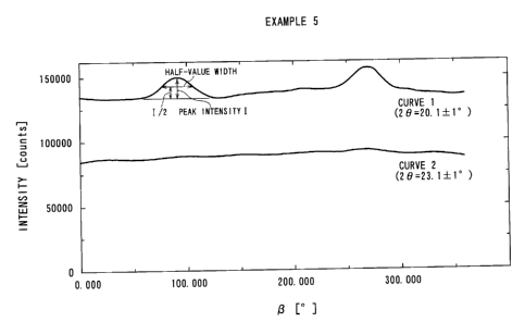
Fig. 3 is a multiply recorded graph of intensity distribution curves
versus azimuths ( a -angles) at 2 8 = 20.1 -~ 1° and at 2 B = 23.0 ~
1°
based on X-ray diffraction corresponding to Fig. 1.
Fig. 4 is a scanning electron microscopic picture (magnification:
5000) of the outer surface of the porous hollow yarn of vinylidene fluoride
resin obtained in Example 5.
Fig. 5 is a scanning electron microscopic picture (magnification:
5000) of the inner surface of the porous hollow yarn of vinylidene fluoride
resin obtained in Example 5.
Fig. 6 is a scanning electron microscopic picture (magnification:
5000) of a cross section proximate to the outer surface of the porous hollow
yarn of vinylidene fluoride resin obtained in Example 5.
Fig. 7 is a scanning electron microscopic picture (magnification:
5000) of a cross section proximate to the inner surface of the porous hollow
yarn of vinylidene fluoride resin obtained in Example 5.
7
CA 02518948 2005-09-12
[BEST MODE FOR PRACTICING THE INVENTION)
Hereinbelow, the porous membrane of vinylidene fluoride resin of the
present invention is described along the steps of the production process
according to the present invention which is a preferred process for
production thereof.
(Vinylidene fluoride resin)
A principal membrane-forming material used in the present invention
is (A) a vinylidene fluoride resin having a weight-average molecular weight
of at least 200,000 and a ratio of weight-average molecular weight /
l0 number-average molecular weight of at least 2.5 (i.e., having a broad
molecular weight distribution); or (B) a vinylidene fluoride resin comprising
2 - 75 wt. % of a first vinylidene fluoride resin having a weight-average
molecular weight of 400,000 - 1,200,000 and 25 - 98 wt. % of a second
vinylidene fluoride resin having a weight-average molecular weight of
150,000 - 600,000 giving a ratio of the weight-average molecular weight of
the first vinylidene fluoride resin/the molecular weight molecular weight of
the second vinylidene fluoride resin of at least 1.2.
The vinylidene fluoride resin used in the present invention may be
homopolymer of vinylidene fluoride, i.e., polyvinylidene fluoride, or a
copolymer of vinylidene fluoride together with a monomer copolymerizable
with vinylidene fluoride, or a mixture of these. Examples of the monomer
copolymerizable with vinylidene fluoride may include: tetrafluoroethylene,
hexafluoropropylene, trifluoroethylene, chlorotrifluoroethylene and vinyl
fluoride, which may be used singly or in two or more species. The
vinylidene fluoride resin may preferably comprise at least 70 mol % as the
constituent unit. Among these, it is preferred to use homopolymer
consisting of 100 mol.% of vinylidene fluoride in view of its high mechanical
8
CA 02518948 2005-09-12
strength.
A vinylidene fluoride resin of a relatively high vinylidene fluoride
content as described above may preferably be obtained by emulsion
polymerization or suspension polymerization, particularly preferably by
suspension polymerization, and the above-mentioned vinylidene fluoride
resin (A) of a broad molecular weight distribution can be obtained by
successively changing the polymerization conditions. More conveniently ,
however, it is preferred to obtain at least two types of vinylidene fluoride
resins having different average molecular weights respectively through
polymerization, and blend these resins to obtain the vinylidene fluoride resin
(B) having a weight-average molecular weight/ number-average molecular
weight ratio of at least 2.5 for use in the present invention. According to a
preferred embodiment of the present invention, a mixture of 5 - 75 wt. % of
the above-mentioned first vinylidene fluoride resin and 25 - 95 wt. % of the
above-mentioned second vinylidene fluoride resin is used a principal starting
material of the membrane.
The vinylidene fluoride resin used in the present invention may
preferably be a non-crosslinked one for easiness of melt-extrusion of the
composition described below, and may preferably have a melting point of
160 - 220 °C, more preferably 170 - 180 °C, further preferably
175 - 179 °C.
Below 160 °C, the resultant porous membrane is liable to have an
insufficient heat distortion resistance, and above 220 °C, the melt-
mixability
of the resin is lowered so that the formation of a uniform film or membrane
becomes difficult.
The melting point means a heat absorption peak temperature
accompanying crystal melting of the resin as measured by means of a
differential scanning calorimeter (DSC).
9
CA 02518948 2005-09-12
According to the present invention, a plasticizes and a good solvent
for vinylidene fluoride resin are added to the above-mentioned vinylidene
fluoride resin to form a starting composition for formation of the membrane.
(Plasticizes)
As the plasticizes, aliphatic polyesters of a dibasic acid and a glycol
may generally be used. Examples thereof may include: adipic acid-based
polyesters of e.g., the adipic acid-propylene glycol type, and the adipic
acid-1,3-butylene glycol type; sebacic acid-based polyesters of, e.g., the
sebacic acid-propylene glycol type; and azelaic acid-based polyesters of e.g.,
the azelaic acid-propylene glycol type type, and azelaic acid-1, 3- butylene
glycol type.
(Good solvent)
As the good solvent for vinylidene fluoride resin, those capable of
dissolving vinylidene fluoride resin in a temperature range of 20 - 250
°C
may be used. Examples thereof may include: N-methylpyrrolidone,
dimethylformamide, dimethylacetamide, dimethyl sulfoxide, methyl ethyl
ketone, acetone, tetrehydrofuran, dioxane, ethyl acetate, propylene
carbonate, cyclohexane, methyl isobutyl ketone, dimethyl phthalate, and
solvent mixtures of these. N-methylpyrrolidone (NMP) is particularly
preferred in view of its stability at high temperatures.
(Composition)
The starting composition for formation of the membrane may
preferably be obtained by mixing 70 - 250 wt. parts of the plasticizes and 5 -
80 wt. parts of the good solvent with 100 wt. parts of the vinylidene fluoride
resin.
Below 70 wt. parts of the plasticizes, the resultant membrane is liable
to have a lower porosity, thus resulting in a battery separator exhibiting
poor
CA 02518948 2005-09-12
impregnatabity with an electrolytic solution or an increased electric
resistance, or a microfiltration membrane exhibiting a poor filtration
performance (water permeation rate). On the other hand, above 250 wt.
parts, the resultant membrane is liable to have an excessively high porosity
and a lower mechanical strength.
Below 5 wt. parts of the good solvent, the uniform mixing of the
vinylidene fluoride resin and the plasticizes is liable to be failed or
require a
long time. On the other hand, above 80 wt. parts, a high porosity cannot be
attained corresponding to the amount of the plasticizes. In other words, an
effective pore formation due to the extraction of the plasticizes is
obstructed.
The total amount of the plasticizes and the good solvent may
preferably be in the range of 100 - 250 wt. parts. These are both effective
for reducing the viscosity of the melt-extruded composition and can function
substitutively for each other to some extent. Among them, the good solvent
should preferably occupy 5 - 30 wt. %.
(Mixing and Melt-extrusion)
The melt-extrusion composition may be extruded into a film by
extrusion through an annular nozzle or a T-die at a temperature of 140 -
270 °C, preferably 150 - 270 °C. Accordingly, the manners of
mixing and
melting of the vinylidene fluoride resin, plasticizes and good solvent are
arbitrary as far as a uniform mixture in the above-mentioned temperature
range can be obtained consequently. According to a preferred embodiment
for obtaining such a composition, a twin-screw kneading extruder is used,
and the vinylidene fluoride resin (preferably in a mixture of the first and
second vinylidene fluoride resins) is supplied from an upstream side of the
extruder and a mixture of the plasticizes and the good solvent is supplied at
a downstream position to be formed into a uniform mixture until they pass
11
CA 02518948 2005-09-12
through the extruder and are discharged. The twin-screw extruder may be
provided with a plurality of blocks capable of independent temperature
control along its longitudinal axis so as to allow appropriate temperature
control at respective positions depending on the contents of the materials
passing therethrough.
(Cooling)
In the process of the present invention, the melt-extruded film
product is cooled and solidified from one surface. As for a flat sheet product
extruded through a T-die, the cooling may be performed by causing the sheet
to contact a surface temperature-controlled cooling drum or roller, and as for
a hollow yarn film extruded through a nozzle, the cooling may be effected by
causing the film to path through a cooling medium, such as water. The
temperature of the cooling drum etc. or cooling medium can be selected from
a broad temperature range but may preferably be in a range of 10 - 100
°C,
particularly preferably 30 - 80 °C.
(Extraction)
The cooled and solidified film product is then introduced into an
extraction liquid bath to remove the plasticizer and the good solvent
therefrom. The extraction liquid is not particularly restricted provided that
it does not dissolve the vinylidene fluoride resin while dissolving the
plasticizer and the good solvent. Suitable examples thereof may include:
polar solvents having a boiling point on the order of 30 - 100 °C,
inclusive of
alcohols, such as methanol and isopropyl alcohol, and chlorinated
hydrocarbons, such as dichloromethane and 1, l, l-trichloroethane.
(Heat treatment)
The film or membrane product after the extraction may preferably be
heat treated at a temperature in a range of 80 - 160 °C, preferably 100
-
12
CA 02518948 2005-09-12
140 °C, for 1 - 3600 sec., preferably 3 - 900 sec. to increase its
crystallinity
for the purpose of providing an improved processability for subsequent
stretching.
(Stretching)
The film or membrane product after the extraction is then subjected
to stretching for increasing the porosity and pore size and improving the
strength and elongation. The stretching can be effected as biaxial
stretching, e.g., by tentering, but may generally preferably be effected as
uniaxial stretching in the longitudinal direction of the film or membrane
product as by a pair of rollers rotating at different peripheral speeds. This
is because it has been found that a microscopic texture including a
stretched fibril portion and a non-stretched node portion appearing
alternately in the stretched direction is preferred for the porous membrane of
vinylidene fluoride resin of the present invention to exhibit a harmony of
porosity and strength-elongation thereof. The stretching ratio may
appropriately be 1.2 - 4.0 times, particularly ca. 1.4 - 3.0 times.
(Elution liquid treatment)
Through the above-mentioned steps, a porous membrane of
vinylidene fluoride resin according to the present invention is obtained, but
2o it is particularly preferred to subject the porous membrane to a treatment
of
immersion in an elution liquid. This is because owing to the elution liquid
treatment, the porous membrane of the present invention can be provided
with a remarkably increased water permeability without essentially
impairing the characteristic properties thereof. As the elution liquid, an
alkaline liquid, an acidic liquid or an extraction liquid for the plasticizer
is
used.
The reason why the water permeability of the porous membrane is
13
CA 02518948 2005-09-12
remarkably increased by the elution liquid treatment has not been fully
clarified as yet, but it is presumed that the plasticizes is exposed at the
minute pore wall enlarged in diameter by the stretching and is effectively
removed by the elution liquid treatment. The alkaline or acidic liquid as the
elution liquid is considered to decompose and solubilize the polyester used
as the plasticizes for the vinylidene fluoride resin, thereby promoting the
elution and removal thereof.
Accordingly, as the alkaline liquid, it is preferred to use an aqueous
solution or a solution in water/alcohol of a strong base, such as sodium
hydroxide, potassium hydroxide or calcium hydroxide, at a pH of at least 12,
preferably 13 or higher. On the other hand, as the acidic liquid, it is
preferred to use an aqueous solution or a solution in water/alcohol of a
strong acid, such as hydrochloric acid, sulfuric acid or phosphoric acid at a
pH of at most 4, preferably 3 or lower.
Farther, as the extraction liquid for the plasticizes, those dissolving
the plasticizes without dissolving the vinylidene fluoride resin can be used
without particular restriction similarly as the one used before the
stretching.
For example, polar solvents having a boiling point of ca. 30 - 120
°C are
suitably used, inclusive of alcohols, such as methanol and isopropyl alcohol,
and chlorinated hydrocarbons, such as dichloromethane, and
1,1,1-trichloromethane.
The elution liquid treatment may be effected by immersing the porous
membrane in the elution liquid at a temperature of ca. 5 - 100 °C for
10 sec.
to 6 hours, after an optional pre-immersion for improving the affinity to the
liquid. In case where the elution liquid treatment is performed at an
elevated temperature, it is preferred to fix the porous membrane so as not to
cause the shrinkage thereof during the treatment.
14
CA 02518948 2005-09-12
(Porous membrane of vinylidene fluoride resin)
The porous membrane of vinylidene fluoride resin of the present
invention obtained as described above may be generally provided with
properties, inclusive of a porosity of 55 - 90 %, preferably 60 - 85 %,
particularly preferably 65 - 80 %; a tensile strength of at least 5 MPa, an
elongation at break of at least 5 %, a tensile yield stress of at least 5 MPa,
preferably at least 6 MPa, a yield elongation of at least 3 %, preferably at
least 5 %, and when used as a water-filtering membrane, a water permeation
rate of at least 5 m3/m2 ~ day at 100 kPa. The thickness is ordinarily in the
range of 5 - 800 a m, preferably 50 - 600 ,u m, particularly preferably 150 -
500 ,u m. In the case of a hollow yarn form, the outer diameter may
suitably be on the order of 0.3 - 3 mm, particularly ca. 1 - 3 mm.
Further, a micro-texture characteristic of the porous membrane of
vinylidene fluoride resin according to the present invention is that it
comprises a crystalline oriented portion and a crystalline non-oriented
portion (random oriented portion) recognizable by X-ray diffraction, which
are understood as corresponding to a stretched fibril portion and a
non-stretched node portion, respectively.
(X-ray diffraction method)
More specifically, the X-ray diffraction characteristics of film or
membrane materials described herein are based on measured results
according to the following method.
If the film is in the form of a hollow yarn, the yarn was split into
halves along a longitudinal direction thereof, and a film sample was attached
to a sample stand so that its longitudinal direction was oriented vertically.
Then, X-rays were incident in a direction perpendicular to the longitudinal
direction. The X-ray generator was "ROTAFLEX 200RB" made by Rigaku
CA 02518948 2005-09-12
Denki K. K., and CuK a rays at 30 kV-100 mA and having passed through an
Ni filter were used as an X-ray source. An imaging plate ("BAS-SR127"
made by Fuji Shashin Film K.K.) was used to photograph a diffraction image
at a sample-imaging plate distance of 60 mm. Fig. 1 represents a diffraction
image obtained with respect to a hollow yarn obtained in Example S
described hereinafter, and Fig. 2 is a explanatory illustration thereof. As is
understandable by referring to Fig. 2, a -angle is an angle formed along a
Debye ring, and 2 8 -angle is an angle formed outwards from the center. Fig.
3 was obtained by multiply recording an intensity distribution curve versus
azimuths ( a -angles) at 2 8 = 20.1 ~ 1° (Curve 1) and an intensity
distribution curve versus azimuths ( a -angles) at 2 8 = 23.1 ~ 1°
(Curve
2), respectively, prepared by X-ray diffraction. The Debye ring at 2 8 = 20.1
-~ 1° represents a diffraction from (110) plane of a-crystal of PVDF
and
the intensity at 2 8 =23.1 -~ 1° represents a background intensity of
the
diffraction X-rays.
In the case of a uniformly non-oriented porous membrane, typically a
porous membrane produced through the extraction process or the phase
conversion process alone, provides no peak or only a broad peak giving a
half value width of at least 90° . Further, as the crystal directions
are at
random, the curve 1 exhibits an intensity higher than the curve 2 at any
azimuths ( ~3 -angles).
On the other hand, in the case of a uniformly oriented sample,
typically a porous membrane obtained through only stretching, the crystal
directions are selectively oriented, the curve 1 shows sharp peaks at
-angles = 90 ° and 270° , i.e., on the equator of a diffraction
image.
Further, the curve 1 shows only a weak intensity at (3 -angles = 0°
and 180
(on the meridian of a diffraction image) . As a result, only a curve 1 / curve
2
16
CA 02518948 2005-09-12
intensity ratio of below 1.1 is given at a -angle = 0° or 180° .
In contrast to the above, the porous membrane of the present
invention comprising an oriented fibril portion and a non-oriented node
portion provides a diffraction image showing a superposition of a diffraction
representing a selectively oriented crystal direction and a diffraction
representing random crystal directions. More specifically, the curve 1 gives
a peak at (3 -angle = 90° or 270° (on the equator of the
diffraction image)
having a half value width of at most 80° , preferably at most
60° , further
preferably at most 40° , attributable to the oriented fibril portion,
and the
curve 1 exhibits an intensity higher than the curve 2 at any azimuths ( a
-angles) and provides a curvel/curve 2 intensity ratio of at least 1.1,
preferably at least 1.2, at a -angle = 0° or 180°
As a result, the presence in mixture of the crystal oriented portion
and the crystal non-oriented portion in the porous membrane of the present
invention can be quantitatively represented by X-ray diffraction parameters
including a diffraction intensity ratio on the meridian of at least 1.1
between
those at diffraction angles 2 B = 20.1 ~ 1° and 2 B = 23.0 ~- 1°
, and an
azimuth intensity distribution curve at 2 8 = 20.1 ~ 1° showing a peak
having a half value width of at most 80° .
[Examples]
Hereinbelow, the present invention will be described more specifically
based on Examples and Comparative Examples. The properties other than
the above-mentioned X-ray diffraction characteristics described herein
including those described below are based on measured values according to
the following methods.
(Weight-average molecular weight (Mw) and number-average molecular
weight (Mn))
17
CA 02518948 2005-09-12
A GPC apparatus ("GPC-900", made by Nippon Bunko K.K.) was used
together with a column of "Shodex KD-806M and a pre-column of "Shodex
KD-G"(respectively made by Showa Denko K.K.), and measurement
according to GPC (gel permeation chromatography) was performed by using
NMP as the solvent at a flow rate of 10 ml/min. at a temperature of 40
°C to
measure polystyrene-based molecular weights.
(Porosity)
The length and also the width and thickness (or outer diameter and
inner diameter in the case of a hollow yarn) of a sample porous membrane
to were measured to calculate an apparent volume V (cm3) of the porous
membrane, and the weight W (g) of the porous membrane was measured to
calculate a porosity according to the following formula:
Porosity (%) _ ( 1 - W / (V x ,o )) x 100,
wherein ,o : density of PVDF (=1.78 g/cm3)
(Water permeation rate (Flux))
A sample porous membrane was immersed in ethanol for 15 min.,
then immersed in water to be hydrophilized, and then subjected to a
measurement at a water temperature of 25 °C and a pressure difference
of
100 kPa. In the case of a hollow yarn-form porous membrane, the area of
2o the membrane was calculated based on the outer diameter according to the
following formula:
Membrane area (m2) _ (outer diameter) X n X (length) .
(Average pore diameter)
An average pore diameter was measured according to the half dry
method based on ASTM F316-86 and ASTM E 1294-89 by using
"PERMPOROMETER CFP-2000AEX" made by Porous Materials, Inc. A
perfluoropolyester (trade name "Galwick") was used as the test liquid.
i8
CA 02518948 2005-09-12
(Maximum pore diameter)
A maximum pore diameter was measured according to the bubble
point method based on ASTM F316-86 and ASTM E 1294-89 by using
"PERMPOROMETER CFP-2000AEX" made by Porous Materials, Inc. A
perfluoropolyester (trade name "Galwick") was used as the test liquid.
(Tensile strength and Elongation at break)
Measured by using a tensile tester ("RTM-100", made by Toyo
Baldwin K.K.) under the conditions of an initial sample length of 100 mm
and a crosshead speed of 200 mm/min. in an environment of a temperature
of 23 °C and a relative humidity of 50 %.
(Tensile yield stress and elongation)
A porous hollow yarn sample was subjected to a tensile test by using
a tensile tester ("RTM-100" made by Toyo Baldwin K.K.) under the conditions
of an initial sample length of 100 mm and a tensile speed of 200 m/min. in
an environment of a temperature of 23 °C and a relative humidity of 50
% to
obtain a strain-stress curve. In case where a maximum of stress appeared,
the maximum stress point was taken as a yield point. The stress and
elongation at the yield point were taken as a tensile yield stress and a
tensile
yield elongation.
Further, from the tensile yield stress, a fibril yield stress was
calculated according to the following formula:
Fibril yield stress (MPa)
- Tensile yield stress x 100/ ( 100 - porosity (%)).
(Example 1 )
A first polyvinylidene fluoride (PVDF) (powder) having a
weight-average molecular weight (Mw) of 6.59 x 10⁵ and a second
polyvinylidene fluoride (PVDF) (powder) having Mw = 2.52 x 10⁵ Were
19
CA 02518948 2005-09-12
blended in proportions of 12.5 wt. % and 87.5 wt. %, respectively, by a
Henschel mixer to obtain a mixture A having Mw = 3.03 x 10⁵ and an
Mw/ Mn (number-average molecular weight) ratio of 2.53.
An adipic acid-based polyester plasticizer ("PN-150", made by Asahi
Denka Kogyo K.K.) as an aliphatic polyester and N-methylpyrrolidone (NMP)
as a solvent were mixed under stirring in a ratio of 87.5 wt. %/ 12.5 wt. % at
room temperature to obtain a mixture B.
An equi-directional rotation and engagement-type twin-screw
extruder ("BT-30", made by Plastic Kogaku Kenkyusyo K.K.; screw diameter:
30 mm, L/ D = 48) was used, and the mixture A was supplied from a powder
supply port at a position of 80 mm from the upstream end of the cylinder
and the mixture B heated to 100 °C was supplied from a liquid supply
port
at a position of 480 mm from the upstream end of the cylinder at a ratio of
mixture A/mixture B - 37.5/62.5 (wt. %), followed by kneading at a barrel
temperature of 210 °C to extrude the melt-kneaded product through a
nozzle
having an annular slit of 7 mm in outer diameter and 3.5 mm in inner
diameter into a hollow yarn-form extrudate at a rate of 13 g/ min.
The extruded mixture in a molten state was introduced into a water
bath having a surface 10 mm distant from the nozzle (i.e., an air gap of 10
mm) to be cooled and solidified (at a residence time in water bath of ca. 10
sec.), pulled up at a take-up speed of 5 m/min. and wound up to obtain a
first intermediate form.
Then, the first intermediate form was fixed so as not to shrink in the
longitudinal direction and, while being kept in the fixed state, was immersed
under vibration in dichloromethane at room temperature for 30 min,
followed by immersion in fresh dichloromethane again under the same
conditions to extract the aliphatic polyester and solvent and further by 1
CA 02518948 2005-09-12
hour of heating in an oven at 120 ~, while being continually fixed, for
removal of the dichloromethane and heat treatment, thereby to obtain a
second intermediate form.
Then, the second intermediate form was longitudinally stretched at a
ratio of 1.6 times at an environmental temperature of 25 °C and then
heated
for 1 hour in an oven at a temperature of 100 ~ for heat setting to obtain a
polyvinylidene fluoride-based porous hollow yarn.
The thus-obtained polyvinylidene fluoride-based porous hollow yarn
exhibited physical properties including: an outer diameter of 1.486 mm, an
inner diameter of 0.702 mm, a thickness of 0.392 mm, a porosity of 72 %, a
water permeation rate of 18.01 m3 / m2 ~ day ~ 1 OOkPa, an average pore
diameter of 0.0864 ,u m, a maximum pore diameter of 0.1839 ~c m, a tensile
strength of 9.1 MPa and an elongation at break of 7 %.
The production conditions and the physical properties of the
resultant polyvinylidene fluoride-based porous hollow membrane are
inclusively shown in Tables 1 and 2 appearing hereinafter together with
those of Examples and Comparative Examples described below.
(Example 2)
A porous hollow yarn was prepared in the same manner as in
Example 1 except that the cooling water bath temperature for cooling the
melt extrudate was changed to 11 °C, and the stretching ratio was
changed
to 1.8 times.
(Example 3)
A porous hollow yarn was prepared in the same manner as in
Example 2 except that the supply ratio of mixture A/ mixture B was changed
to 42.9/57.1 (wt. %).
(Example 4)
21
CA 02518948 2005-09-12
A porous hollow yarn was prepared in the same manner as in
Example 2 except that the mixing ratio of the first PVDF/the second PVDF
was changed to 50/50 (wt. %) to obtain a mixture A, the air gap was
increased to 40 mm and the stretching ratio was changed to 2.4 times.
(Example 5)
A porous hollow yarn was prepared in the same manner as in
Example 4 except that the stretching ratio was changed to 1.8 times.
An X-ray diffraction picture of the resultant porous hollow yarn is
shown in Fig. 1 and an explanatory note thereof is given in Fig. 2. Further,
Fig. 3 shows a multiply recorded graph of intensity distribution curves
versus azimuths ( a -angles) at 2 8 = 20.1 ~ 1° and at 2 8 = 23.0 ~
1°
Further, scanning electron microscopic photographs (at a
magnification of 5000) of an outer surface, an inner surface, a cross-section
proximate to the outer surface and a cross-section proximate to the inner
surface of the resultant porous hollow yarn, are shown in Figs. 4 - 7,
respectively.
(Example 6)
A porous hollow yarn was prepared in the same manner as in
Example 5 except that the cooling water bath temperature was changed to
40 °C and the air gap from the nozzle to the cooling bath surface was
changed to 40 mm.
(Examples 7 - 9)
Porous hollow yarns were prepared in the same manner as in
Example 6 except that the cooling was bath temperatures were changed to
60 °C (Example 7), 70 °C (Example 8) and 11 °C (Example
9), respectively.
(Example 10)
A porous hollow yarn was prepared in the same manner as in
22
CA 02518948 2005-09-12
Example 2 except that a mixture A was formed by changing the ratio of the
first PVDF/ the second PVDF to 5/ 95 (wt. %), and the air gap was changed to
mm.
(Comparative Example 1)
5 The preparation of porous hollow yarn was tried in the same manner
as in Example 5 except that a PVDF having a weight-average molecular
weight of 4.92 X 10⁵ was used alone instead of the mixture A, the
PVDF/mixture B supply ratio was changed to 42.9/57.1 wt. % (same as in
Example 3) and the stretching ratio was changed to 2.0 times, whereas the
yarn was severed during the stretching.
(Comparative Example 2)
A porous hollow yarn was prepared under the same conditions as in
Comparative Example 1 except that the take-up speed after cooling and
solidification of the melt-extruded composition was changed to 10 m/min.
(Comparative Example 3)
The production of porous hollow yarn was tried under the same
condition as in Example S except that the first PVDF (Mw = 6.59 X 10⁵) was
used alone instead of the mixture A, the PVDF/mixture B supply ratio was
changed to 33.3 / 66.7 (wt. %) and the air gap was changed to 300 mm,
whereas the yarn was severed during the stretching.
(Comparative Example 4)
A porous hollow yarn was prepared under the same conditions as in
Comparative Example 3 except that the stretching ratio was lowered to 1.3
times.
(Comparative Example 5)
A porous hollow yarn was prepared under the same conditions as in
Comparative Example 3 except that the take-up speed after cooling and
23
CA 02518948 2005-09-12
solidification of the melt-extruded composition was changed to 10 m/min.
(Comparative Example 6)
The production of porous hollow yarn was tried under the same
condition as in Example 2 except that a PVDF of Mw = 2.52 x 10⁵ (used as
the second PVDF in Example 2) alone was used instead of the mixture A,
whereas the yarn was severed during the stretching.
(Comparative Example 7)
The production of porous hollow yarn was tried under the same
condition as in Comparative Example 6 except that the take-up speed after
cooling and solidification of the melt-extruded composition was changed to
10 mimin., whereas the yarn was severed during the stretching.
(Comparative Example 8)
A porous hollow yarn was prepared under the same conditions as in
Comparative Example 6 except that the take-up speed after cooling and
solidification of the melt-extruded composition was changed to 20 m/min.
The physical properties of porous hollow yarns that could be obtained
without causing severance of yarn during the stretching are inclusively
shown in Table 2.
24
CA 02518948 2005-09-12
u~ ui
u7 ~ N .- W O~
Om0 ~ ~ ~ tn ~ ~ ~ N ~ M n ~" O .~-, ONO. 00
u7 CV CV Z .~ O O ""' O
0.. ~ ~ O
0o co
m u7
p~ ~ uN7 ~ ~ ~ ~ ~ ~ ~ ~~", ~r7 ~ ~ ~ ~ ~ ~ ' ' ~ 0 ,~ 00
v0 N O ~ CV z ~ ~ N O
O O
00 C~
N ~
O O _
00 ~ ~ ~ ~ ~ ~ w ~ ~ C~ ~ 00 ~ ~ O N N '8 O
t0 CV ~ ~t CV ~ ~ ~ ~ '~ ~; ~p Od' ~
L~ t~ O
00 M
m u~
~ 'err' u'~ d~~' ~ 'N° ~o~ ~ ~i~
o~ ~ ~ ~ yn °~ a_ t~ M ~ o ~ ' '
vo ca ~ v c5 z z o 0
a. t~ ~ " °~ 0 0
00 M
u7 U7
0~ N O
~3~~~ ~ ~ ~g~°~~~~~go~o~~~'~
~ Nzz
'n a. ~ ~ 0 0 0 0 ,-'
d0 M
u7 W
~ WO d u0~7 ~ ~ _ ~ N N ~ 00 ~ ~ 0~ .~ 00
v0 N ~ ~r C'i ~ N ~ j ~ " ~ ,~ ~ ~ ~ ~ ~ ~, c~ ~ M O~
l' I" O O O O
a0 M
d ~ ~ ~ ~ ~ ~~'" ~ ~ d O\ N ~ 00 ~' N N 00
~O CV W t N Z u7 tn ~ '-' ~ N ~ ~ V' n W ~ ~. l~
p, ~ ~ ~ O O
00 M
N
O
M M ~ ~ ~ ~ ~ ~ ~ ~ d
1~ ~ ' ' ~~p'~~0~
r~ O O
M
u7
N U~7 ~ ~ O N ~ ~ ~ N O ~ ~ M O M
.-' I~ d (rj O 00 00 00 ~ M
t0 CV ~ c~7 CV Wl7 ~f -~ ~ ~ d t\ ~ ~ 1\ OW"
N L1. is I~ ~" p p ~' p O
0o m
wn u~
0
.-, ~ t~ ~ O VM7 ~ ~ ~ ~ O O y0 ~ ~ ~ N O ~ ~ ~~ pW
~O N N M N Z N N ~ ~O .-: d: t M G 00 O pv ~ CO ~
CV 0. t~ h- ~-~ O O
~" DO M
~s
x
7
0
~-~ N ~ N .
_v ~~ ~ ~ a
cue' o
W
', °= ~' b . a ~i
ao ~
~n ~ 3 E-. ~'n ~ ~ ~ n° 3 Q ~ E-. w
b
:p
F-~ g ~ ~ 8
CA 02518948 2005-09-12
O
N v N n 0.~ ~ N
~
O ~ N ~ \ \ O '."'0 0' O,
O VM
N z ~ N Nz z ~?~ ' "N ~ ( ~
,-O
U 0.. ~ O
DOM
u7u)
o
.N v N lWf7 ~ tN
u LL
o ~ N ,~\ \ o .-
o
~ z ~ N ~izz ~ ~n ~ *
U a.
DOM
.o ~ mn
o
,N v N t~ C4.-N.
m ~
o N ~ \ \ o ~ ,n *
N z ~iNz z ~n~n ~ *
U 0..
M
u7 ~ t
0 o
a n~ ci.~ ~ o~M M
o m cy ~ ~ o~ No vou
, \ \ yo
o~ z ~ ~oNz z ~ M M ~ ~ ~~-N,~
U 0. ~ ~,.~ 00 0
M
y n ~
0
o w~ a.~ ~ o vo ~
O u7N ~ \ \ M ~ ~O
O~ z ~ ~ONz z ~ M O ~ u7 v0~ WO n
M
U a. ~ ~,.~ '-'0 0
00M
M N l~
0
u)C \ ' 'n~ 0.,~ ~ o
~
O N ~ \ \ O ~ tn~
O~ z y 0 Nz z ~ M M , ~
U a.
M
N
o
,N N M~ a.,_N..,~ ~t l~
o ~ -.o o" <r
o~'Z ~ ~ c~i Z ~ ..,-.N 0 ~ o .~ mv
~ ~ o 0
u)
'-'.N ~ v N ~o ~
~ L ~
O O
o z 0 z N *
~ ~
~ ~ ~ Nz ? ~ ~
U a.
o C~.
x ~ ~ ~
o
x . >
'
~ b 3 ~
a,> ~ x
.o
!x.~ W m 3~ o NS~ o
CaL_ N ~uCl1'.
i. U
~ b4
D.Q,>
0.
.
~ O ~ o" d ' ~
. .~ ~
i~
. a(
N ~ N
~ C
\ .
U
au
U
v
0
0
U ~ ~~ ~ 0..
Wp O L ~ ~~ ~ ~~ ~~
' '4
t O G 0
. c, ' ~.~ c.
~ ~
'
f ;~ ~ ~ a~ "n
.~
0.o a~
.
.~ ro~~ ~ ~ ~~ C'
~
c~ a~,. o
a ~'' oa '~ o o ~':
~ ~ ~ '~
.' a ' . a.'ro
x >
~ ao~ ~~ -. ~n ~ a,~ ow
m c, ~ .
~ . 3 E r~o ~.Co. > ~ .
ra ~.. . 3 y..w
Q E-n Q
-a
N ia ~ ~
.o a
o
~
a~ ~ g is
. .
~
~
_ o
a' ~ >
~ p
~
,
f/7 .
~
O . N,
L~. Q
V!
U
CA 02518948 2005-09-12
(Example 11 )
The porous hollow yarn obtained in Example 1 was fixed so as not to
shrink in the longitudinal direction and, while being kept in the fixed state,
was immersed in ethanol for 15 min. and then in water for 15 min. to be
hydrolyzed, followed further by 1 hour of immersion in 20 %-caustic soda
aqueous solution (pH 14) maintained at 70 °C, washing with water and 1
hour of drying in a hot oven maintained at 60 °C.
(Example 12)
The porous hollow yarn obtained in Example 1 was fixed so as not to
shrink in the longitudinal direction and, while being kept in the fixed state,
was immersed in ethanol for 15 min. and then in water for 15 min. to be
hydrolyzed, followed further by 1 hour of immersion in 35 % hydrochloric
acid aqueous solution (pH 1) at room temperature, washing with water and 1
hour of drying in a hot oven maintained at 60 °C.
(Example 13)
The porous hollow yarn obtained in Example 1 was fixed so as not to
shrink in the longitudinal direction and, while being kept in the fixed state,
was immersed under vibration in dichloromethane for 30 min. and again
immersed in fresh dichloromethane under the same conditions, followed
further by 1 hour of drying in a hot oven maintained at 60 °C.
The porous hollow yarns obtained after the elution liquid treatments
in Examples 11 to 13 were subjected to measurement of porosity, water
permeation rate, average pore diameter, maximum pore diameter, tensile
strength and elongation at break. The results are inclusively shown in
Table 3 below in parallel with those of Example 1.
27
CA 02518948 2005-09-12
Table 3
Example 11 12 13 1
Elution AlkalineAcidicOrganicNone
liquid 1i uid 1i solvent
uid
Porosity (%) 74 73 75 72
Water permeation rate (m3/m~''day'36.6 31.8 35.7 18.01
100kPa)
PhysicalAverage pore diameter (Nm) 0.0964 0.09140.08900.0864
propertiesMaximum pore diameter (Nm) 0.1840 0.18000.08100.1839
Tensile strength (MPa) 7.1 9.3 9.7 9.1
Elongation at break (%) 6 9 13 7
[Industrial applicability]
As is understood from the results in Table 1 in comparison with Table
2, the present invention provides a porous membrane of vinylidene fluoride
resin which has pores of appropriate size and distribution and also excellent
mechanical strength represented by tensile strength and elongation at break
and is useful as a microfiltration membrane or a separator for batteries, by
subjecting a melt-extruded composition obtained by mixing a vinylidene
1o fluoride resin having a molecular weight distribution which is
appropriately
broad and high as a whole with a plasticizer and a good solvent for
vinylidene fluoride resin, to cooling for solidification from one surface,
extraction of the plasticizer and stretching. Further, in view of Table 3, it
is
found possible to attain a remarkably increased water permeation rate by
the subjecting the thus-obtained porous membrane (Example 1) to treatment
with an elution liquid of alkali, acid or organic solvent.
28