Note: Descriptions are shown in the official language in which they were submitted.
CA 02518990 2005-09-13 PCT/AU2004/000316
Received 14 January 2005
-1-
TITLE: A SEPARATE SIZE FLOTATION DEVICE
FIELD OF THE INVENTION
The present invention relates to flotation devices of the type used in mineral
separation and will be described hereinafter with reference to this
application. However,
it will be appreciated that the invention is not limited to this particular
field of use.
BACKGROUND OF THE INVENTION
The following discussion of the prior art is intended to place the invention
in an
appropriate technical context and to allow its benefits to be fully
appreciated. Any
statements about the prior art should not, however, be considered as
admissions that
to such prior art is widely known or forms part of common general knowledge in
the field.
Conventional flotation devices typically include a tank for receiving and
containing slurry from a grinding mill, cyclone separator, or the like. An
agitator,
comprising a rotor housed within a stator, is normally disposed within the
tank, and
activated via a motor and drive shaft to agitate the slurry. An aeration
system is also
provided to direct air under pressure into the agitator through a central
conduit formed
within the drive shaft. Suitable reagents are also added, which coat the
surfaces of the
mineral particles within the slurry to make the particles hydrophobic and
thereby to
preferentially promote bubble to particle attachment. As bubbles dispersed by
the rotor
rise toward the surface of the tank, they carry with them floatable valuable
mineral
2o particles, which form a mineral enriched surface froth. The froth then
migrates over a
lip and into a launder whereby the valuable mineral particles suspended in the
froth are
recovered from the tank as a mineral concentrate. The gangue particles
remaining
suspended in the slurry, along with those mineral particles that were not
removed by
flotation, are continuously discharged from the tank through a bottom outlet.
The
bottom outlet often incorporates a dart or pinch valve, which is opened to
allow the
remaining slurry to progress under gravity feed to downstream treatment
processes. It is
normal practice to control the pulp level in each device using a PID
controller, a level
indicating probe and a control valve in the form of a dart, pinch or other
suitable type of
valve.
3o The slurry that is transferred through the bottom outlet includes both
relatively
coarse or dense particles as well as a large number of relatively fine
particles, including
Amended Sheet
IPEA/AU
CA 02518990 2005-09-13
-2
[AMENDED PAGE]
gangue slimes such as clay minerals, not removed by flotation. The slimes
consist of
very fme particles and accordingly have a total surface area much greater than
that of the
coarse particles. Accordingly, when a flotation reagent is added to the
outflow from the
tank, the majority tends to be absorbed by the slimes, which are not
floatable, making
the flotation process non-selective. Consequently, most of the coarser
valuable particles
do not receive sufficient flotation reagent to make them hydrophobic, even
given
extended conditioning times.
The flotation process can be made more efficient where coarse and fine
particles
are treated separately and in the past, devices such as hydrocyclones and
hydrosizers
l0 have been used to separate a flotation feed stream into two discrete
streams for separate
processing. However, the capital cost of this equipment is high, making the
prior art
methods uneconomical for all but the most valuable ore bodies.
It is an object of the present invention to overcome or substantially
ameliorate
one or more disadvantages of the prior art, or at least to provide a useful
alternative.
SUMMARY OF THE INVENTION
Accordingly, a first aspect of the present invention provides a flotation
device
including:
a sequence of at least two flotation tanks arranged relatively as an upstream
tank
and a downstream tank, each of said tanks being adapted to receive slurry
incorporating
fine and coarse particles containing minerals to be extracted, and each of
said tanks
including:
a feed inlet for admission of slurry;
agitation means to agitate the slurry;
aeration means to aerate the slurry whereby floatable minerals in suspension
float
upwardly to form a surface froth;
an overflow launder for removal of the surface froth; and
a bottom outlet for withdrawal of relatively coarse or dense components of the
slurry;
wherein the bottom outlet from the upstream tank is connected to the feed
inlet of
3o the downstream tank whereby a relatively dense fraction of the slurry
including a
relatively high proportion of coarse or dense components is withdrawn from the
CA 02518990 2005-09-13
-3
[AMENDED PAGE]
upstream tank and fed directly to the downstream tank for reprocessing in the
downstream tank; and
wherein at least one of said tanks includes an upper side outlet adapted for
withdrawal of a relatively fine fraction of the slurry including a relatively
high
proportion of fine or lower density components for separate size processing
independently of the upstream and downstream tanks.
Preferably the flotation device comprises a sequence of three or more of said
tanks connected in series, with the bottom outlet of each tank save for the
last being
connected to the feed inlet of the tank immediately downstream.
l0 Preferably each of said tanks includes a respective upper side outlet.
Preferably each of said tanks includes a substantially flat base and wherein
the
bottom outlet of each tank is formed in a sidewall of the tank adjacent the
base.
Preferably at least one of said side outlets is adapted to remove slurry
containing
a relatively high proportion of gangue slimes from the top half of the tank.
Preferably at least one of said side outlets is adapted to remove slurry
containing
a relatively high proportion of gangue slimes from between a mixing zone of
the rotor
and a froth zone near the tank surface.
Preferably at least one of said side outlets is adapted to remove slurry from
the
top third of the tank.
2o Preferably at least one of said side outlets includes a fluid conduit
extending
inwardly from the tank sidewall.
Preferably the conduit terminates near the centre of the respective tank,
generally
proximal a vertical axis thereof.
Preferably at least one of said side outlets directs the lower density
components
to a separate slurry processing unit configured for optimal treatment of
relatively fine
particles.
Preferably at least one of said tanks further includes a top substantially
hollow
deflection cone fixed with respect to the tank and extending generally around
the drive
shaft.
3o Preferably at least one of said tanks further includes a fluid conduit
extending
through a sidewall of the top cone to the respective side outlet to facilitate
fluid transfer
from within the top cone to the side outlet.
CA 02518990 2005-09-13
-4
[AMENDED PAGE]
Preferably said at least one tank further includes a bottom substantially
hollow
deflection cone, also extending generally around the drive shaft, at a
position below said
top deflection cone.
Preferably the bottom cone is axially movable relative to the drive shaft to
allow
an area of an annular opening between the top and bottom cones to be
selectively
adjusted.
Preferably a lower end of the top cone is nested at least partially within an
upper
end of the bottom cone.
Preferably the top cone is truncated and includes an opening at its lowermost
end.
Preferably the lowermost end of the bottom cone fits relatively closely around
the drive shaft, thereby substantially to impede slurry flow through a region
between the
lowermost end of the bottom cone and the drive shaft.
Preferably the agitation means of each of said tanks includes a rotor
supported
for rotation within a surrounding stator, and operable by means of a central
drive shaft
extending downwardly into the respective tank.
Preferably the aeration means of each of said tanks includes an air blower and
a
fluid conduit for directing air from the blower into the respective agitation
means.
Preferably the fluid conduit of the aeration means includes an axial bore
2o extending through the drive shaft of the respective rotor.
Preferably each of said tanks is generally in the shape of a right circular
cylinder.
Preferably the bottom outlet of each of said tanks is defined by an opening in
the
lower half of the tank.
Preferably the opening defining the bottom outlet of each of said tanks is
defined
in the respective tank sidewall adjacent the tank floor.
Preferably the opening defining the bottom outlet of each of said tanks is
defined
in the respective tank floor adjacent the tank sidewall.
Preferably the flotation device includes a plurality of downstream tanks
connected in series, each configured for optimal treatment of a slurry
including a
3o relatively high proportion of relatively coarse or dense components and
each having an
inlet connected to the bottom outlet of its adjacent upstream tank.
CA 02518990 2005-09-13
-S-
[AMENDED PAGE]
Preferably all of the downstream tanks are substantially identical, with each
tank
including a side outlet for withdrawal of relatively lower density components
of the
slurry from an adjacent upstream tank.
Preferably a side outlet of each tank directs lower density slurry components
to a
separate slurry processing unit configured for optimal treatment of relatively
fine
particles.
Preferably only the third and subsequent tanks in the series include a side
outlet
for withdrawal of relatively lower density components of the slurry from the
tank.
Preferably a plurality of said tanks is arranged in pairs, wherein the level
of the
base of each successive tank pair is lower than the base of its adjacent
upstream pair,
such that slurry flows under the influence of gravity from one tank pair to
the next.
Preferably the plurality of tanks is arranged in groups of more than two,
wherein
the level of the base of each successive tank group is lower than the base of
the adjacent
upstream group, such that slurry flows under the influence of gravity from one
tank
group to the next.
Preferably the outlet from one tank pair to the adj acent downstream tank pair
includes a valve to allow discharge of the relatively coarse or dense
components of the
slurry.
Preferably the valve is a dart valve.
Preferably the valve is positioned substantially within the tank adjacent the
outlet.
Preferably the valve is positioned in a conduit extending between adjoining
tanks.
Preferably each tank has a capacity of at least 100m3.
Preferably the slurry entering said upstream tank via the feed inlet includes
less
than around 55% solids.
Preferably the agitation means of each tank is aligned with the respective
feed
inlet, such that feed slurry entering the tank flows directly into the
agitation means.
A second aspect of the invention provides a method of separate size flotation
3o including the steps of
providing a flotation device according to the first aspect of the invention;
CA 02518990 2005-09-13
-6
[AMENDED PAGE]
directing a feed slurry into the flotation device through the feed inlet of
the
upstream tank;
withdrawing the relatively dense fraction of the slurry through the bottom
outlet
of the upstream tank and feeding that fraction through the feed inlet of the
downstream
tank, for reprocessing in the downstream tank; and
withdrawing the relatively fine fraction of the slurry through the side outlet
for
separate size processing independently of the upstream and downstream tanks.
Preferably after withdrawal through the side outlet, the relatively fine
fraction of
the slurry is directed into one or more downstream fine particle flotation
tanks
to specifically configured for optimal recovery of relatively fine particles.
Preferably after withdrawal from the tank and where the fine particles are
predominantly gangue slimes, they are discarded.
Preferably after withdrawal from the tank, the relatively coarse or dense
components are directed into a separate series of one or more downstream
coarse
particle flotation tanks.
Preferably the method includes the steps of providing a sequence of three or
more of said tanks, and connecting said tanks in series with the bottom outlet
of each
tank save for the last being connected to the feed inlet of the tank
immediately
downstream.
2o Preferably the method includes the further step of providing each of said
tanks
with a respective upper side outlet.
Preferably the method includes the further step of positioning each downstream
tank at a level below the tank immediately upstream thereof, to facilitate
gravity feed of
slurry through the series of tanks.
Preferably the method includes the step of adding a flotation reagent to the
slurry
in the downstream tanks.
Preferably the method includes the step of diluting the slurry in the
downstream
tanks.
Preferably the tanks have a capacity of at least 100m3.
3o Preferably the feed slurry includes less than around 55% solids.
CA 02518990 2005-09-13
[AMENDED PAGE]
BRIEF DESCRIPTION OF THE DRAWINGS
A preferred embodiment of the invention will now be described, by way of
example only, with reference to the accompanying drawings in which:
Figure 1 is a diagrammatic cross-sectional side elevation showing a flotation
device according to the invention;
Figure 2 is a schematic view showing a network of the flotation devices; and
Figure 3 is a schematic view of an alternative network arrangement.
PREFERRED EMBODIMENTS OF THE INVENTION
The illustrated flotation device is adapted for use in extracting valuable
minerals
to from the cyclone overflow from a grinding circuit. This overflow is in the
form of a
slurry and typically includes mineral particles having a P80 of between around
SOpm to
around 220~m. However, the slurry also contains gangue slimes, which contain
few
recoverable valuable minerals, but which tend to absorb a high proportion of
flotation
reagents that are added to the slurry to facilitate recovery of the valuable
minerals. It is
emphasised that the illustrated flotation device differs from other flotation
devices, such
as flash flotation cells or "Skim Air" cells, which are typically located
upstream in the
grinding mill circuit and are used to process slurries containing much coarser
particles
and also having a higher percentage of solids. Typically, Skim Air cells are
used to
process slurries containing around 65% solids, whereas the illustrated
flotation device is
2o configured to process slurnes with up to around SO% to 55% solids. It is
also noted that
Skim Air cells are configured to cause around 70% to 80% of the solids to
bypass the
rotor. This 70% to 80% of solids contains most of the coarse material from the
feed
slurry, which if fed into the rotor causes significant rotor wear. However, in
conventional cells, such as those shown in the drawings, the feed slurry
contains much
smaller particles, and accordingly, the slurry is caused to pass directly
through the rotor.
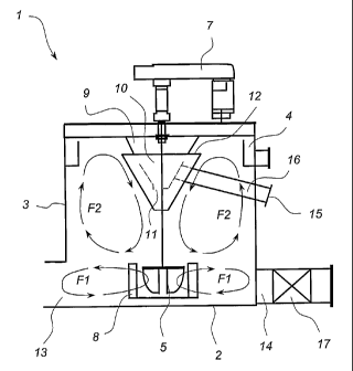
Referring to the drawings, the invention provides a flotation device including
a
tank 1 containing a slurry incorporating minerals to be extracted. Typically,
the tank
would have a capacity of at least 100m3, however in some alternative
embodiments,
smaller tanks are used. The tank includes a generally flat base 2 and a
substantially
3o cylindrical sidewall 3 extending upwardly from the base. A peripheral
overflow launder
4 extends around the inside top of the sidewall for removing mineral enriched
froth as it
floats to the surface.
CA 02518990 2005-09-13
_ g _
[AMENDED PAGE]
An agitator is disposed to agitate the slurry within the tank. The agitator
includes
a rotor 5 mounted on a centrally disposed drive shaft 6 extending axially
downwardly
into the tank and driven by a motor 7. A stator 8 is also provided around the
rotor. As
shown in the drawings, the rotor is located close to the floor of the tank,
such that when
feed slurry enters the tank it flows directly through the rotor.
Axially spaced top and bottom hollow froth deflection cones 9 and 10 are also
provided. The cone sidewalk extend around the drive shaft adjacent the top of
the tank
and each cone is oriented such that its smallest diameter is located at its
lowermost end
nearest the rotor 5. The top cone 9 is truncated and includes an opening 11 at
its
l0 lowermost end. However, the lowermost end 12 of the bottom cone fits
relatively
closely around the drive shaft 6, substantially to prohibit slurry flow
through this region.
The top cone is fixed with respect to the tank and the lower cone 10 is
axially
movable along the drive shaft 6 to allow the area of an annular opening 12
between the
partially nested cones to be adjusted. In use, the lower cone 10 is moved
toward the
is rotor 5 to increase the area of the opening or away from the rotor to
reduce the area of
the opening 12.
The flotation device further includes an aeration system including an air
blower
and a fluid conduit (not shown) to direct air from the blower into the
agitator: The
conduit is defined in part by an axial bore (not shown) extending through the
drive shaft
20 6 of the rotor.
Feed slurry is introduced into the tank 1 through a feed inlet 13 formed in
the
sidewall of the tank. A bottom outlet 14 is formed in the lower portion of the
tank
sidewall 3 to allow removal of relatively coarse or dense components of the
slurry. A
side outlet 15 is provided to remove slurry containing a relatively high
proportion of the
25 gangue slimes for separate downstream treatment. The side outlet includes a
fluid
conduit 16 connected to the top cone 9. The conduit passes through a slot (not
shown) in
the sidewall of the bottom cone. A flexible seal (not shown) is provided
around the
conduit 16 to seal the slot. The conduit is located in the top third of the
tank and is
adapted to remove slurry from within the top deflection cone 9. The side
outlet also
3o includes a valve (not shown) to control flow of fluid from the top cone.
The valve can
be a pinch valve, or may be a weir type arrangement, or any other suitable
alternative.
CA 02518990 2005-09-13
-9
[AMENDED PAGE]
As will be appreciated by those skilled in the art, particle size distribution
varies
within the tank based on the initial composition of the slurry, and relevant
system
parameters such as tank geometry, aeration rate and the normal operating speed
of the
agitator. Moreover, it is known that the gangue slimes present in the slurry
do not float,
despite the fact that they absorb a significant amount of the flotation
reagents added to
the slurry to facilitate recovery of the valuable mineral particles.
Accordingly, the size
and location of the opening 12 between the deflection cones is adjusted on the
basis of
these parameters and the flotation kinetics of the gangue slimes to correspond
with a
position within the tank having a relatively high concentration of gangue
slimes. This
to position is above a mixing zone of the rotor and below a froth zone near
the top of the
tank. Adjusting the area of the opening controls the fluid velocity through
the opening,
and hence the size range of particles entering the bottom cone 10. In this
way, the
system can be optimised to remove a majority of the gangue slimes through the
side
outlet without loss of valuable minerals.
Turning now to describe the operation of the flotation device in more detail,
slurry is initially fed into the tank via feed inlet 13, from where it
migrates toward the
agitation and aeration assemblies positioned near the bottom of the tank. The
action of
the rotor 5 induces a primary flow through the slurry as indicated by arrows
F1. The
primary flow continuously recirculates the slurry at the bottom of the tank to
maintain
2o the particles in suspension. The aeration system continuously disperses air
into the rotor
5 to form fine bubbles which collide with and adhere to the valuable mineral
particles in
the slurry and subsequently float to the top of the tank to form a mineral
enriched surface
froth. As the froth floats toward the surface, it is directed radially
outwardly by the
deflection cones for recovery through the overflow launder 4. The rotor also
induces a
secondary flow through the slurry as indicated by arrows F2.
As targeted finer particles move in the direction indicated by arrows F2, they
are
drawn into the opening 12 between the deflection cones. From there, they pass
downwardly through the bottom cone 10, up through the opening 11 in the top
cone,
through conduit 16 and out through the side outlet 15. The fine particles are
processed
3o downstream separately from the outflow from the bottom outlet 14.
Simultaneously, due
to their buoyancy and upward velocity, valuable mineral particles which have
become
CA 02518990 2005-09-13
-10
[AMENDED PAGE]
attached to bubbles from the aeration system rise into the froth zone near the
top of the
tank for recovery via the overflow launder.
Any gangue particles remaining suspended in the slurry, along with those
mineral
particles that were not removed by flotation, are continuously discharged from
the tank
through the bottom outlet 14. From there, the coarse particles are directed
initially into a
second tank that is substantially identical to the first tank.
In the embodiment illustrated in Figure 2, this second tank includes a base 2
located at a lower level than the base of the first tank such that slurry
feeds into the
second tank under gravity. From the second tank, the slurry flows under
gravity into a
l0 plurality of substantially similar downstream tanks, each.connected in
series. Respective
dart valves 17 control flow of slurry between adjacent tanks.
In the embodiment illustrated in Figure 3, the second tank is located at the
same
level, such that the first and second tanks define a first tank pair. From the
second tank,
the slurry flows under the influence of gravity into a plurality of downstream
tank pairs,
each substantially identical to the first pair. Flow of slurry between the
tank pairs is
controlled by respective dart valves 17, which are continuously adjusted to
maintain the
pulp level in the cell. As shown in Figure 3, the base of each subsequent tank
pair is
lower than that of the adjacent upstream tank pair.
It will be appreciated that in alternative embodiments, the tanks may be
disposed
2o at the same level and the slurry may be pumped between the tanks. Also, in
some
situations, it may be preferable to include side outlets on only some of the
downstream
tanks. It will also be appreciated that hybrid and other network combinations,
including
tanks connected in series, parallel or a combination of both, may be employed,
as
required. It will further be understood that different valve types, and
different forms of
conduit between the tanks, may alternatively be used. In still further
embodiments, the
aeration system may supply air to the rotor through a pipe with a discharge
point located
underneath the rotor. In yet another embodiment, such as that illustrated in
Figure 3, the
deflection cones are omitted and the conduit 16 extends from the side outlet
15 to
terminate at a position in the top third of the tank, near the drive shaft 6.
3o In the illustrated embodiments, it will be appreciated that the outflow
slurry from
each tank has a higher proportion of coarser particles than was present in the
inflow
slurry from the upstream tanks, since some of the finer particles are removed
through the
CA 02518990 2005-09-13
-11
[AMENDED PAGE]
side outlets 15. Accordingly, the proportion of coarse particles in the slurry
increases as
the feed liquid migrates progressively through the network of tanks.
Consequently,
when a flotation reagent is added to the slurry in the downstream tanks, there
is a greater
probability of coating some of the larger particles. Therefore, the
probability of floating
these larger particles increases in the downstream tanks. This in turn
increases the
overall efficiency of the flotation process.
As described above, the flotation device permits a slurry stream containing
both
fine and coarse particles to be separated progressively into two parallel
branches, with
one branch containing the relatively coarse particles from the stream and the
other
to branch containing the finer particles. In this way, the two branches can be
individually
optimised for the treatment of either coarse or fine particles, which
optimises the
efficiency and cost effectiveness of the overall separation process. It will
therefore be
appreciated that the invention provides both practical and commercially
significant
advantages over the prior art.
While the invention has been described with reference to conventional
flotation
cells, it will be appreciated that the same principles may be applied to other
flotation
cells, such as flash flotation cells, or Skim Air cells. Moreover, although
the invention
has been described with reference to specific examples, it will be appreciated
by those
skilled in the art that the invention may be embodied in many other forms.